EP0843154A2 - Verfahren und Vorrichtung zum Messen der Form eines Objektes - Google Patents
Verfahren und Vorrichtung zum Messen der Form eines Objektes Download PDFInfo
- Publication number
- EP0843154A2 EP0843154A2 EP97309131A EP97309131A EP0843154A2 EP 0843154 A2 EP0843154 A2 EP 0843154A2 EP 97309131 A EP97309131 A EP 97309131A EP 97309131 A EP97309131 A EP 97309131A EP 0843154 A2 EP0843154 A2 EP 0843154A2
- Authority
- EP
- European Patent Office
- Prior art keywords
- under inspection
- object under
- shape
- image
- interference
- Prior art date
- Legal status (The legal status is an assumption and is not a legal conclusion. Google has not performed a legal analysis and makes no representation as to the accuracy of the status listed.)
- Withdrawn
Links
Images


Classifications
-
- G—PHYSICS
- G01—MEASURING; TESTING
- G01B—MEASURING LENGTH, THICKNESS OR SIMILAR LINEAR DIMENSIONS; MEASURING ANGLES; MEASURING AREAS; MEASURING IRREGULARITIES OF SURFACES OR CONTOURS
- G01B11/00—Measuring arrangements characterised by the use of optical techniques
- G01B11/002—Measuring arrangements characterised by the use of optical techniques for measuring two or more coordinates
-
- G—PHYSICS
- G01—MEASURING; TESTING
- G01B—MEASURING LENGTH, THICKNESS OR SIMILAR LINEAR DIMENSIONS; MEASURING ANGLES; MEASURING AREAS; MEASURING IRREGULARITIES OF SURFACES OR CONTOURS
- G01B11/00—Measuring arrangements characterised by the use of optical techniques
- G01B11/24—Measuring arrangements characterised by the use of optical techniques for measuring contours or curvatures
Definitions
- the present invention relates to a method of measuring and checking a shape of a fine object or an article by using an interference image between light having information about the shape of the object and reference light.
- the invention also relates to an apparatus for carrying out such a method.
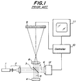
- Fig. 1 is a schematic view showing a known shape measuring device.
- This shape measuring device utilizes the Twyman-Green interferometer.
- a parallel coherent light beam emitted by a laser 1 is expanded by a beam expander 2.
- the expanded parallel laser beam is made incident upon an interference optical system 3 formed by a half mirror and is divided thereby into an inspection laser beam which is directed toward an object 4 under inspection along an inspection optical path 5 and a reference laser beam which is directed toward a reference body 6 along a reference optical path 7.
- the inspection and reference laser beams are reflected by the object 4 and reference body 6, respectively and are made incident again upon the interference optical system 3 along the inspection and reference optical paths 5 and 7, respectively.
- these laser beams are composed each other to produce a composite laser beam due to an interference.
- the composite laser beam is then made incident upon an objective lens 8 and an interference image of the object 4 and the reference body 6 is formed on an image sensing device 9.
- An image signal obtained by the image sensing device 9 is supplied to an image display device 11 via a controller 10 and the interference image is displayed thereon.
- interference fringes In the interference image displayed on the image display device 11, there are produced interference fringes in accordance with a local difference in an optical path length between the inspection optical path 5 and the reference optical path 7. Therefore, during the reference body 6 is moved in the direction of the optical axis by driving a phase modulator 12 from the controller 10 to vary the difference in optical path length finely, a plurality of interference images are picked-up by the image sensing device 9. This operation is generally called the fringe scan. Then, a phase distribution in a vicinity of a surface of the object 4 can be calculated from the interference images.
- a shape of an object under inspection may be estimated by deriving one or more phase singular points in the phase distribution.
- the known shape measuring apparatus using a phase singular point has the following problem. That is to say, in the known apparatus, only the lateral position of a phase singular point is detected and the position of an optical discontinuity on the surface of an object under inspection is estimated from the thus detected lateral position of the phase singular point. Therefore, if a recess-like microstructure is formed on an object surface, it is possible to measure the width of the recess, but the depth of the recess could not be measured.
- the known shape measuring apparatuses using an interferometer show a detected phase distribution as it is, which does not always give the correct shape of the object under inspection. For instance, in a detection of the lateral position of an optical discontinuity using a phase singular point, the detected lateral position of the phase singular point does not always coincide with the actual point of the optical discontinuity on the object surface, and thus a measured width of a recess formed on the object surface can be different from the actual value. Moreover, by the known shape measuring apparatuses, the depth of a recess formed on an object surface could not be measured at all.
- the present invention has for its object to provide a novel and useful method of measuring a shape of an object under inspection using an interferometer, in which the shape of the object can be measured precisely.
- a method of measuring a shape of an object under inspection comprises the steps:
- the relative position between one or more phase singular points and the reference point of the object under inspection is detected, and the shape of the object under inspection can be measured or estimated by performing the calculation on the basis of the detected relative position. That is to say, a correlation between the relative position and the actual shape of the object has been previously provided theoretically or experimentally, and the shape of the object can be estimated precisely in accordance with the thus obtained correlation.
- the interference image is formed by using two orthogonally polarized light components. Then, the position of a phase singular point can be detected for respective polarized light components, and therefore the shape of the object under inspection can be estimated much more precisely.
- the interference images are formed by using a plurality of light having different wavelengths and the position of a phase singular point is detected for respective interference images. Then, the shape of the object can be determined very accurately.
- the shape of the object under inspection is estimated by using predetermined shape parameters. Then, the calculation can be carried out simply. That is to say, correlations between the shape parameters and the relative position between the phase singular points and the reference points of the object are previously determined by calculation or experiences. Then, a shape parameter can be easily derived from the detected relative position between the phase singular points and the reference points. In this manner, the shape of the object under inspection can be measured very precisely.
- the shape parameter includes at least one of the width, the height and the refractive index of a structure formed on a surface of an object under inspection.
- the shape parameter includes the width of the structure, the width of a line in the inspection of IC and a magnetic disc can be easily measured.
- the shape parameter includes a height, it is possible to measure the thickness of a lead pattern in IC.
- the shape pattern includes the refractive index, it is possible to measure the amount of impurity doped into a silicon substrate.
- an apparatus for measuring a shape of an object under inspection comprises:
- the position of a phase singular point are detected while the focus of the image forming means with respect to an object under inspection is adjusted by the focus adjusting means.
- the shape of the object under inspection can be estimated precisely by using a previously determined correlation between the shape of the object and the detected relative position of the phase singular point.
- a polarization modulating means is arranged in the optical path of the image forming means to produce two orthogonally polarized light beams, and the first and second phase singular points are detected by using the two orthogonally polarized light beams, respectively. Then, the shape of the object can be estimated in accordance with the thus detected first and second phase singular points in an accurate manner.
- the light source means generates a plurality of light beams having different wavelengths, and a plurality of phase singular points are detected for respective light beams. Then, a plurality of relative positions are derived in accordance with a plurality of phase singular points and the position of the reference point of the object under inspection. Then, the shape of the object under inspection can be estimated much more precisely in accordance with a plurality of the thus detected relative positions.
- the inventor of the present application has conducted a detailed and deep analysis for the electric field generated in a vicinity of the surface of an object under inspection and has found that a phase singular point does not always occur on the surface of the object under inspection, but the height or level of the phase singular point is changed in accordance with the surface shape of the object under inspection. It has been further confirmed that when a phase singular point appears at a point which is apart from the surface of an object under inspection, the lateral position of the singular point does not coincide with the lateral position of the optical discontinuous point of the object under inspection.
- Fig. 2 is a schematic cross sectional view showing a model of an object under inspection (diffraction grating) used in the electric field analysis.
- a silicon oxide (SiO 2 ) substrate 15 on which silicon oxide (SiO 2 ) substrate 15 are formed silicon nitride films (Si 3 N 4 ) 16 having a width of 1.5 ⁇ m and a thickness (t) of 0.2 ⁇ m, said films being arranged side by side with a pitch of 2 ⁇ m. Then, the width (w) of a gap between opposing edges of adjacent silicon nitride films 16 becomes 0.5 ⁇ m as shown in Fig. 2.
- Refractive indices n of the silicon oxide substrate 15 and silicon nitride film 16 are assumed to be 1.5 and 2, respectively.
- the P-polarized light has the electric field component which is in parallel with the gratings formed on the object surface (perpendicular to the plane of the drawing of Fig. 2)
- the S-polarized light has the electric field component which is at right angles to the P-polarized light (parallel with the plane of the drawing of Fig. 2).
- phase singular points due to the structure of the object are not produced on the object surface, but at different heights h with respect to the surface of the object.
- the height of the phase singular point for the P-polarized light differs from that for the S-polarized light. Moreover, for the S-polarized light, the distance s between adjacent phase singular points does not coincide with the width w of the gap formed on the surface of the object.
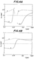
- Fig. 4A shows a correlation between the thickness t of the Si 3 N 4 film 16 and the height h at which two singular points appear measured from a reference point of the object, i.e. the top surface of the Si 3 N 4 film 16 and the distance s between adjacent phase singular points for the P-polarized light
- Fig. 4B illustrates a similar correlation for the S-polarized light
- Fig. 5A depicts a correlation between the width w of the gap formed in the Si 3 N 4 film 16 and the height h at which two singular points appear and the distance s between two phase singular points for the P-polarized light
- Fig. 5B represents a similar correlation for the S-polarized light.
- the height h at which two adjacent phase singular points appear and the distance s between these phase singular points are changed greatly in accordance with the thickness t of the Si 3 N 4 film 16 and the width w of the gap formed in the Si 3 N 4 .
- the distance s between adjacent phase singular points is not identical with the width w of the gap formed in the Si 3 N 4 film 16.
- the inventor has recognized the above fact and has found a recognition that the thickness t of Si 3 N 4 film 16, i.e. the depth of the gap can be measured by detecting the height h and the distance s for S-polarized light.
- the height h is changed substantially linearly in accordance with the thickness t for S-polarized light, and therefore the thickness t can be measured precisely only by detecting the height h for the S-polarized light.
- the depth t can be measured accurately by detecting the height h only for the P-polarized light.
- the width w of the recess formed in the Si 3 N 4 film 16 can be estimated by measuring the height h and the distance s of the phase singular points, while a correlation between the height h and the distance s for recesses having various widths have been previously derived as shown in Figs. 5A and 5B. In this manner, a correlation between the height h and the distance s for predicted various thicknesses t and widths w has been derived by calculation (simulation) or experience, and the thus derived correlation is stored. Then the thickness t and the width w of the object under inspection can be estimated precisely by detecting a matching between actually measured values of the height h and the distance s and the previously derived and stored thicknesses t and widths w.
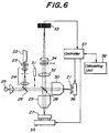
- Fig. 6 is a schematic view showing an embodiment of a shape measuring apparatus according to the invention.
- the shape measuring apparatus comprises a reference mirror 21 formed by a precisely manufactured plane mirror.
- the apparatus further comprises a laser light source 22 emitting a linearly polarized laser beam, a quarter wavelength plate 23 converting the linearly polarized laser beam into a circularly polarized laser beam, a beam expander 24 increasing the diameter of the laser beam into a desired diameter, a white light source 25 and a dichroic mirror 26 which combine the laser beam and the white light beam each other to form an illumination light beam.
- the shape measuring apparatus comprises a half mirror 28 which divides the illumination light beam into an inspection light beam and a reference light beam and combines the light beams reflected by an object 27 under inspection and the reference mirror 21 to produce an interference.
- a half mirror 28 and the object 27 there is arranged an inspection objective lens 29, and between the half mirror 28 and the reference mirror 21 there is provided a reference objective lens 30, a back focal point of which is conjugated with that of the inspection objective lens 29.
- a Köhler lens 31 is removably arranged in the optical path between the dichroic mirror 26 and the half mirror 28. When the Köhler lens 31 is inserted into the optical path, a back focal point of the Köhler lens substantially coincides with the pupils of the inspection objective lens 29 and the reference objective lens 30.
- the shape measuring apparatus further comprises an image forming lens 32 which forms an image of the interference formed by the half mirror 28 at a predetermined image plane, and an image sensing element 33 having a light receiving surface arranged on said predetermined plane.
- the image sensing element 33 may be formed by CCD.
- an analyzer 34 which constitutes a polarization modulating means.
- the analyzer 34 is arranged removably from the optical path and rotatably about the optical axis.
- the object 27 under inspection is placed on a focus adjusting device 35 including a piezo-electric element. By driving the focus adjusting device 35, a focus adjustment of the object 27 under inspection with respect to the inspection objective lens 29 can be carried out.
- the reference mirror 21 is provided on a retardation adjusting device 36 having a piezo-electric element, by means of which the retardation of the reference light can be adjusted.
- the focus adjusting device 35 and retardation adjusting device 36 are connected to a controller 37 to effect the above control.
- the image sensing element 33 is also connected to the controller 37 and an image signal supplied from the image sensing element is processed by the controller 37.
- the controller 37 is connected to a calculation unit 38.
- a step 51 the object 27 under inspection is set on the focus adjusting device 35, and in a step 52, the analyzer 34 is operated to select the P-polarized light or S-polarized light under which phase singular points are to be detected.
- the object 27 is moved to effect the focus adjustment such that the focus of the inspection objective lens 29 comes in a vicinity of the surface of the object 27.
- analyzer 34 is removed from the optical path, the Köhler lens 31 is inserted into the optical path and the white light source 25 is ignited. Then, the white light beam is converged at the pupil of the inspection objective lens 29 by means of the dichroic mirror 26, the Köhler lens 31 and the half mirror 28.
- the parallel illumination light beam is made incident upon the object 27 under inspection to illuminate a larger area of the object.
- the illumination light is also converged at the pupil of the reference objective lens 30, but is not made incident upon the reference mirror 21 by means of a shutter (not shown). Therefore, no reference illumination light is made incident upon the half mirror 28 from the reference mirror 21.
- the object 27 under inspection is illuminated by the white illumination light from the white light source 25, and an image of the object 27 is formed on the light receiving plane of the image sensing element 33 by means of the inspection objective lens 29, the half mirror 28 and the image forming lens 32.
- An image signal supplied from the image sensing element 33 is processed by the controller 37 and a bright field image is displayed on an image display not shown.
- a user adjusts the focus adjusting device 35 by means of the controller 37 to move the object 27 under inspection along the optical axis such that the focus of the inspection objective lens 29 comes in a vicinity of the object surface.
- this focus control may be carried out automatically by processing the image signal supplied from the image sensing element 33 via the controller 37 in the calculation unit 38 to derive a focus adjusting signal which is then supplied to the focus adjusting device 35 via the controller 37.
- the white light source 25 is extinguished and the analyzer 34 is inserted into the optical path. Further the Köhler lens 31 is removed from the optical path and the laser light source 22 is actuated to emit a laser beam.
- the linearly polarized laser beam is converted by the quarter wavelength plate 23 into a circularly polarized laser beam, which is then converted into a parallel laser beam having a large diameter by the beam expander 24.
- the parallel laser beam is reflected by the dichroic mirror 26 and is divided into two laser beams by the half mirror 28. One of the two laser beams is made incident upon the object 27 under inspection as a fine spot by the inspection objective lens 29 and the other laser beam is made incident upon the reference mirror 21 as a fine spot by means of the reference objective lens 30.
- the above mentioned shutter (not shown) is opened.
- the laser beams reflected by the object 27 under inspection and the reference mirror 21 are made incident upon the half mirror 28 by means of the objective lenses 29 and 30, respectively and are composed each other to form an interference.
- An image of the thus formed interference is projected onto the image sensing element 33 by means of the image forming lens 32 and the analyzer 34. In this manner, the image sensing element 33 receives a coherent interference image of the predetermined polarized light.
- a step 54 the retardation adjusting device 36 is driven by the controller 37 and the reference mirror 21 is moved in a stepwise manner along the optical axis to perform a fringe scan.
- a step 55 interference images obtained at respective steps in the fringe scan are stored in the calculation unit 38.
- phase patterns are derived from the interference images obtained at respective steps of the fringe scan and stored in the calculation unit 38.
- phase singular points are detected in the step 57, then in a step 58, position information t1 of the focus adjusting device 35 at this time is stored in the calculation unit 38 by means of the controller 37.
- the focus adjusting device 35 is driven by the controller 37 to move the object 27 under inspection along the optical axis by a small increment in a step 59, and after that the above mentioned steps 54-57 are repeated. In this manner, the object 27 is moved along the optical axis step by step until phase singular points are detected.
- the above explained operation is performed repeatedly for the respective light beams.
- the distance s between the detected and stored phase singular points is calculated in the calculation unit 38, and the thus calculated distance s is stored in the calculation unit.
- a step 61 the laser light source 22 is extinguished or the laser beam is cut by the shutter not shown.
- the white light source 25 is ignited.
- an operation similar to that defined by the step 53 is conducted in a step 62 and the object 27 under inspection is moved along the optical axis such that the focus of the inspection objective lens 29 becomes in a vicinity of the object surface.
- an incoherent interference is formed by composing, at the half mirror 28, the light beams reflected by the object 27 and reference mirror 21, respectively.
- An image of the incoherent interference is picked-up by the image sensing element 33.
- the analyzer 34 is remained to be removed from the optical path.
- a step 63 the output signal of the image sensing element 33 is stored in the calculation unit 38, and then in a step 64, a contrast of fringes of the stored incoherent interference image is detected.
- the incoherent interference image formed on the image sensing element 33 has a maximum contrast of fringes when the optical path length of the inspection light path is identical with the optical path length of the reference light path.
- a step 65 it is judged whether or not the detected contrast of fringes of the incoherent interference image is maximum.
- the object 27 under inspection is moved along the optical axis by a small distance by driving the focus adjusting device 35, and then the steps 63-65 are repeated until the maximum contrast of interference fringes can be found.
- the inspection objective lens 29 can be focused precisely on a predetermined reference point of the object 27, e.g. the top surface of the object 27 under inspection. Then, in a step 67, position information t2 of the focus adjusting device 35 at this instant is stored in the calculation unit 38 by means of the controller 37.
- the position information t1 and t2 have been detected and stored in the calculation unit 38.
- the shape parameters t and w are estimated on the basis of the distance s between the phase singular points obtained in the step 60 and the relative position h obtained in the step 68. That is to say, the correlation between the shape parameters t and w and the detected values s and h has been previously formed theoretically and experimentally and have been stored in the calculation unit 38.
- the stored shape parameters t and w are retrieved by the detected values s and h to derive an optimum set of the shape parameters. It should be noted that the thus retrieved shape parameters t and w may be corrected by using an interpolation. The thus obtained shape parameters t and w are displayed on the display device not shown.
- the width w of the recess-like structure formed on the surface of the object 27 can be estimated much more precisely than the known shape measuring apparatuses and further the depth t of a recess-like structure which could not be detected by the known shape measuring apparatuses can be estimated accurately.
- an interference image can be selectively obtained for either P-polarized light beam and S-polarized light beam.
- the shape of the object can be estimated much more accurately.
- the illumination light can be converged at the pupil of the inspection objective lens 29 and thus a large area of the object 27 can be illuminated and monitored. Therefore, the focus adjustment in the steps 53 and 62 can be carried out easily and precisely.
- a reference position of the object under inspection may be determined at will such that the reference position can be observed easily. If an object has a relatively large flat surface area, this flat surface may be selected as a reference position. Moreover, a marker may be provided on the object surface and this marker may be used as a reference position.
- a reference position of the object under inspection may be detected by any other methods.
- a reference position may be detected by the heterodyne method using a laser light source emitting a plurality of wavelengths.
- a reference position may be directly detected by using a probe such as an atomic force microscope.
Landscapes
- Physics & Mathematics (AREA)
- General Physics & Mathematics (AREA)
- Length Measuring Devices By Optical Means (AREA)
- Instruments For Measurement Of Length By Optical Means (AREA)
Applications Claiming Priority (3)
| Application Number | Priority Date | Filing Date | Title |
|---|---|---|---|
| JP30147696 | 1996-11-13 | ||
| JP301476/96 | 1996-11-13 | ||
| JP30147696A JP3693771B2 (ja) | 1996-11-13 | 1996-11-13 | 形状測定方法および装置 |
Publications (2)
| Publication Number | Publication Date |
|---|---|
| EP0843154A2 true EP0843154A2 (de) | 1998-05-20 |
| EP0843154A3 EP0843154A3 (de) | 2000-04-05 |
Family
ID=17897369
Family Applications (1)
| Application Number | Title | Priority Date | Filing Date |
|---|---|---|---|
| EP97309131A Withdrawn EP0843154A3 (de) | 1996-11-13 | 1997-11-13 | Verfahren und Vorrichtung zum Messen der Form eines Objektes |
Country Status (3)
| Country | Link |
|---|---|
| US (1) | US6061136A (de) |
| EP (1) | EP0843154A3 (de) |
| JP (1) | JP3693771B2 (de) |
Cited By (3)
| Publication number | Priority date | Publication date | Assignee | Title |
|---|---|---|---|---|
| EP1003010A2 (de) * | 1998-11-17 | 2000-05-24 | Mitutoyo Corporation | Interferometer und Messverfahren zu dessen Anwendung |
| CN110869696A (zh) * | 2018-06-25 | 2020-03-06 | 科美仪器公司 | 耐振白色光干涉显微镜及其振动影响去除方法 |
| CN117006971A (zh) * | 2023-09-25 | 2023-11-07 | 板石智能科技(深圳)有限公司 | 一种三维形貌测量系统 |
Families Citing this family (14)
| Publication number | Priority date | Publication date | Assignee | Title |
|---|---|---|---|---|
| KR20020011416A (ko) * | 1999-05-18 | 2002-02-08 | 조셉 제이. 스위니 | 마스트와 비교함으로써 물체의 검사를 수행하는 방법 및장치 |
| JP4765140B2 (ja) * | 2000-05-22 | 2011-09-07 | 株式会社ニコン | 干渉計測方法および干渉計測装置 |
| DE10202120A1 (de) * | 2002-01-21 | 2003-07-31 | Scinex Ag Zug | Interferometrische optische Anordnung |
| JP2006300661A (ja) * | 2005-04-19 | 2006-11-02 | Kobe Steel Ltd | 干渉計,フーリエ分光装置 |
| JP4197340B2 (ja) * | 2006-01-16 | 2008-12-17 | アンリツ株式会社 | 三次元形状測定装置 |
| JP4197339B2 (ja) * | 2006-01-16 | 2008-12-17 | アンリツ株式会社 | 三次元形状測定装置 |
| JP4180084B2 (ja) * | 2006-03-30 | 2008-11-12 | アンリツ株式会社 | 三次元形状測定装置及び測定方法 |
| JP4452815B2 (ja) * | 2007-07-31 | 2010-04-21 | レーザーテック株式会社 | 深さ測定装置 |
| EP2144050B1 (de) * | 2008-07-11 | 2010-09-15 | Optopol Technology S.A. | Spektrumstomographie mit optischer Kohärenz |
| US20110032534A1 (en) * | 2009-05-19 | 2011-02-10 | Camtek Ltd | System and a method for broadband interferometry |
| CN103424077A (zh) * | 2012-05-23 | 2013-12-04 | 联想(北京)有限公司 | 运动检测装置、检测方法和电子设备 |
| JP5704150B2 (ja) * | 2012-11-21 | 2015-04-22 | 株式会社東京精密 | 白色干渉装置及び白色干渉装置の位置及び変位測定方法 |
| CN106767500B (zh) * | 2016-11-25 | 2019-03-22 | 天津大学 | 用于形貌测量的光路系统 |
| CN106441157B (zh) * | 2016-11-25 | 2019-01-22 | 天津大学 | 一种复杂形貌快速测量方法 |
Citations (3)
| Publication number | Priority date | Publication date | Assignee | Title |
|---|---|---|---|---|
| WO1995009343A1 (en) * | 1993-09-28 | 1995-04-06 | Zygo Corporation | Interferometric method and apparatus to measure surface topography |
| WO1996006324A1 (de) * | 1994-08-19 | 1996-02-29 | Velzel Christiaan H F | Verfahren und interferenzmikroskop zum mikroskopieren eines objektes zur erzielung einer auflösung jenseits der beugungsgrenze (superauflösung) |
| US5555471A (en) * | 1995-05-24 | 1996-09-10 | Wyko Corporation | Method for measuring thin-film thickness and step height on the surface of thin-film/substrate test samples by phase-shifting interferometry |
Family Cites Families (2)
| Publication number | Priority date | Publication date | Assignee | Title |
|---|---|---|---|---|
| US5479259A (en) * | 1991-05-20 | 1995-12-26 | Hitachi, Ltd. | Method and apparatus for detecting photoacoustic signal |
| JPH05232384A (ja) * | 1992-02-18 | 1993-09-10 | Olympus Optical Co Ltd | 干渉顕微鏡 |
-
1996
- 1996-11-13 JP JP30147696A patent/JP3693771B2/ja not_active Expired - Fee Related
-
1997
- 1997-11-12 US US08/967,938 patent/US6061136A/en not_active Expired - Fee Related
- 1997-11-13 EP EP97309131A patent/EP0843154A3/de not_active Withdrawn
Patent Citations (3)
| Publication number | Priority date | Publication date | Assignee | Title |
|---|---|---|---|---|
| WO1995009343A1 (en) * | 1993-09-28 | 1995-04-06 | Zygo Corporation | Interferometric method and apparatus to measure surface topography |
| WO1996006324A1 (de) * | 1994-08-19 | 1996-02-29 | Velzel Christiaan H F | Verfahren und interferenzmikroskop zum mikroskopieren eines objektes zur erzielung einer auflösung jenseits der beugungsgrenze (superauflösung) |
| US5555471A (en) * | 1995-05-24 | 1996-09-10 | Wyko Corporation | Method for measuring thin-film thickness and step height on the surface of thin-film/substrate test samples by phase-shifting interferometry |
Non-Patent Citations (3)
| Title |
|---|
| CREATH K: "PHASE-MEASUREMENT INTERFEROMETRY TECHNIQUES" PROGRESS IN OPTICS, vol. 26, 1 January 1988 (1988-01-01), pages 350-393, XP000560101 * |
| TYCHINSKY V P ET AL: "COMPUTERIZED PHASE MICROSCOPE FOR INVESTIGATION OF SUBMICRON STRUCTURES" OPTICS COMMUNICATIONS,NL,NORTH-HOLLAND PUBLISHING CO. AMSTERDAM, vol. 74, no. 1/02, 1 December 1989 (1989-12-01), pages 37-40, XP000071159 ISSN: 0030-4018 * |
| TYCHINSKY V: "WAVEFRONT DISLOCATIONS AND REGISTERING IMAGES INSIDE THE AIRY DISK" OPTICS COMMUNICATIONS,NL,NORTH-HOLLAND PUBLISHING CO. AMSTERDAM, vol. 81, no. 1 / 02, 1 February 1991 (1991-02-01), pages 131-137, XP000172773 ISSN: 0030-4018 * |
Cited By (5)
| Publication number | Priority date | Publication date | Assignee | Title |
|---|---|---|---|---|
| EP1003010A2 (de) * | 1998-11-17 | 2000-05-24 | Mitutoyo Corporation | Interferometer und Messverfahren zu dessen Anwendung |
| EP1003010A3 (de) * | 1998-11-17 | 2001-09-12 | Mitutoyo Corporation | Interferometer und Messverfahren zu dessen Anwendung |
| CN110869696A (zh) * | 2018-06-25 | 2020-03-06 | 科美仪器公司 | 耐振白色光干涉显微镜及其振动影响去除方法 |
| CN110869696B (zh) * | 2018-06-25 | 2021-12-28 | 恒邦解决方案有限公司 | 耐振白色光干涉显微镜及其振动影响去除方法 |
| CN117006971A (zh) * | 2023-09-25 | 2023-11-07 | 板石智能科技(深圳)有限公司 | 一种三维形貌测量系统 |
Also Published As
| Publication number | Publication date |
|---|---|
| EP0843154A3 (de) | 2000-04-05 |
| JP3693771B2 (ja) | 2005-09-07 |
| US6061136A (en) | 2000-05-09 |
| JPH10141926A (ja) | 1998-05-29 |
Similar Documents
| Publication | Publication Date | Title |
|---|---|---|
| US5956141A (en) | Focus adjusting method and shape measuring device and interference microscope using said focus adjusting method | |
| US6061136A (en) | Method for measuring shape of object and apparatus for carrying out the same | |
| US5202748A (en) | In situ process control system for steppers | |
| US7595891B2 (en) | Measurement of the top surface of an object with/without transparent thin films in white light interferometry | |
| US6545761B1 (en) | Embedded interferometer for reference-mirror calibration of interferometric microscope | |
| US10288408B2 (en) | Scanning white-light interferometry system for characterization of patterned semiconductor features | |
| JP2007533977A (ja) | 波面操作および改良3d測定方法および装置 | |
| Bowe et al. | White light interferometric surface profiler | |
| JP2005519460A (ja) | 重ね合わせ測定方法およびシステム | |
| JP4188515B2 (ja) | 光学式形状測定装置 | |
| US6965435B2 (en) | Interferometer system for measuring surface shape | |
| JPH0654221B2 (ja) | 段差測定装置およびその方法 | |
| KR101716452B1 (ko) | 디지털 홀로그래피 마이크로스코프를 이용한 고단차 측정 방법 | |
| JPH1089912A (ja) | 干渉顕微鏡 | |
| KR20050044591A (ko) | 간섭계를 이용한 배열 방법 | |
| JP3693767B2 (ja) | 形状測定器 | |
| US8035821B2 (en) | Interferometric system having a reference surface including a mirrored zone | |
| EP1890105A1 (de) | Interferometervorrichtung und Interferometerverfahren | |
| JP2000097633A (ja) | マーク位置検出装置およびこれを用いたマーク位置検出方法 | |
| JP2000088546A (ja) | 形状測定装置および測定方法 | |
| KR20090068838A (ko) | 표면 형상 검사 장치 | |
| KR101677585B1 (ko) | 고속 초점위치 이동을 위해 다중파장 광원을 이용하는 3차원 형상 측정장치 | |
| Vandenberg et al. | Quantitative evaluation of optical surfaces using an improved Foucault test approach | |
| JPH0469508A (ja) | 非接触式形状測定装置及び形状測定法 | |
| JPS6318208A (ja) | 面形状測定装置 |
Legal Events
| Date | Code | Title | Description |
|---|---|---|---|
| PUAI | Public reference made under article 153(3) epc to a published international application that has entered the european phase |
Free format text: ORIGINAL CODE: 0009012 |
|
| AK | Designated contracting states |
Kind code of ref document: A2 Designated state(s): AT BE CH LI |
|
| AX | Request for extension of the european patent |
Free format text: AL;LT;LV;MK;RO;SI |
|
| PUAL | Search report despatched |
Free format text: ORIGINAL CODE: 0009013 |
|
| AK | Designated contracting states |
Kind code of ref document: A3 Designated state(s): AT BE CH DE DK ES FI FR GB GR IE IT LI LU MC NL PT SE |
|
| AX | Request for extension of the european patent |
Free format text: AL;LT;LV;MK;RO;SI |
|
| RIC1 | Information provided on ipc code assigned before grant |
Free format text: 7G 01B 11/24 A, 7G 01B 9/04 B, 7G 01B 9/02 B |
|
| AKX | Designation fees paid |
Free format text: AT BE CH LI |
|
| REG | Reference to a national code |
Ref country code: DE Ref legal event code: 8566 |
|
| STAA | Information on the status of an ep patent application or granted ep patent |
Free format text: STATUS: THE APPLICATION IS DEEMED TO BE WITHDRAWN |
|
| 18D | Application deemed to be withdrawn |
Effective date: 20001006 |