EP0842644B1 - Attachement dentaire - Google Patents
Attachement dentaire Download PDFInfo
- Publication number
- EP0842644B1 EP0842644B1 EP97118930A EP97118930A EP0842644B1 EP 0842644 B1 EP0842644 B1 EP 0842644B1 EP 97118930 A EP97118930 A EP 97118930A EP 97118930 A EP97118930 A EP 97118930A EP 0842644 B1 EP0842644 B1 EP 0842644B1
- Authority
- EP
- European Patent Office
- Prior art keywords
- hole
- dental attachment
- attachment according
- cam
- bolt
- Prior art date
- Legal status (The legal status is an assumption and is not a legal conclusion. Google has not performed a legal analysis and makes no representation as to the accuracy of the status listed.)
- Expired - Lifetime
Links
Images

Classifications
-
- A—HUMAN NECESSITIES
- A61—MEDICAL OR VETERINARY SCIENCE; HYGIENE
- A61C—DENTISTRY; APPARATUS OR METHODS FOR ORAL OR DENTAL HYGIENE
- A61C13/00—Dental prostheses; Making same
- A61C13/225—Fastening prostheses in the mouth
- A61C13/265—Sliding or snap attachments
- A61C13/2653—Sliding attachments
Definitions
- the invention relates to a dental attachment for releasable attachment of a Dental prosthesis on a residual tooth with one matrix and one from the matrix recorded patrix, which is arranged on one side of a crossbar, the with its other side is formed on a web, in which a cone and a thread having bore is introduced, the longitudinal center line of which is on the center line the patrix and the transverse web dividing and ending in the web slot, and which is inserted into a receiving cap, one with the bore of the web has aligned bore.
- Dental attachments are used to attach prostheses and removable bridges application. It is on a residual tooth or on one attached a milled tooth stump to a die, which in assembled state a patrix that forms part of the prosthesis or bridge.
- the patrix has a continuous along its longitudinal center line Slit, whereby two slats are formed. The slats are at Fitting the male part into the female part with the help of a spreading tool, creating a exact and tight fit of the male part in the female part is achieved. This process is done with "Activation" referred to.
- a bed load is known (cf. EP 0 239 821 B1) in which the slot is located in continues a cross bar formed on the patrix.
- an activating screw is provided at the end of the slot.
- the screw has a cone at one end, which is used for spreading when screwing in the slats leads.
- one to the one in the crossbar bore has parallel threaded bore (cf. "dental-labor", XLIV, Issue 8/96 p. 1279 Fig. 1).
- the attachment When the attachment is assembled, it is Web inserted into a receiving cap, one with the threaded hole has aligned opening, so that a fastening screw through the opening screwed into the threaded hole of the web can be.
- This attachment shows - as well as other known attachments (cf. EP 0 085 781 B1; DE 9 100 784 U) - the disadvantage that for fastening and To activate the attachment two screws are needed. The construction is therefore expensive.
- the activation screw is also located in assembled condition of the attachment in the area of the papilla of the remaining tooth or ground tooth stump, causing gum irritation and inflammation can lead.
- the invention seeks to remedy this.
- the invention is based on the object To create dental attachment with which only for attachment and activation a screw is necessary. According to the invention, this object is achieved solved that in the bore of the web and in the bore of the receptacle one the receptacle through its bore penetrating fastening and locking device in the form of a cone having screw bolt is arranged.
- a dental attachment is created to activate and fasten only one screw needed.
- the screw is in one area arranged, the approximately between the previously used Activation and Fixing screws.
- the Possibility given them from the area of the papilla of the ground tooth To be arranged away, so that the risk of irritation and inflammation of the Gums is reduced.
- the only screw is in an easily accessible area of the bed load.
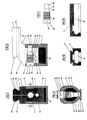
- the attachment selected as an embodiment consists of a die 1 into which a patrix 2 is inserted in the assembled state of the attachment.
- a crossbar 3 is formed, from the side facing away from the male 2 web 4 arranged at right angles to the longitudinal center line of the male part 2 is formed.
- the Web 4 is with a fastening and locking device in the form of a bolt 5 Mistake.
- the male part 2 Along the longitudinal center line of the male part 2 are the male part 2, the transverse web 3 and part of the web 4 divided by a slot 6.
- the web 4 is in assembled state of the attachment in a receiving cap 7 used.
- the die 1 has an essentially cuboid shape.
- On the the Male 2 facing away from the die 1 has a dovetail-shaped Training 11 on.
- the training 11 is used to attach the die 1 to one Remaining tooth or a crown, not shown, on a ground Tooth stump is attached.
- On its side facing away from the formation 11, the Matrix a recess 12 for receiving the male 2.
- the male part 2 is through the slot 6 along its longitudinal center line in two lamellae 21, 22 divided.
- the slats 21, 22 are by means of two intermediate pieces 23, 24 the crossbar 3 connected.
- the shape of the male 2 is due to the shape of the Die 1 determined.
- the lamellae 21, 22 of the male part 2 deliver the positive the negative formed by the recess 12 in the die 1.
- the crossbar 3 has a bevel 31 at one end. With the slant 31, the crosspiece 3 protrudes beyond the male part 2. On his slope 31 end facing away from the crossbar 3 has a taper 32. That of the slopes 31 opposite end of the crosspiece 3 is flush with the male part 2. By doing The non-tapered area of the crosspiece 3 is on the side facing away from the male part 2 the web 4 is arranged.
- the web 4 has the shape of a cylinder with an elliptical base area.
- the jetty 4 is arranged at right angles to the longitudinal center line of the cross bar 3 on this.
- a through hole 41 which is parallel to the Longitudinal center lines of the male part 2 and the transverse web 3 runs.
- hole 41 there is a thread 44.
- the longitudinal center line of the bore 41 runs in the Level of the slot 6.
- the web 4 has a parallel to the bore 41 Hole 42 on.
- the bore 42 is located on the cross bar 3 facing away Side of the bore 41.
- the longitudinal center line of the bore 42 also runs in the Level of the slot 6.
- the end 61 of the slot 6 is on the Transverse web 3 facing away from the bore 42.
- the web 4 has an enlarged diameter. This is all around the jetty its side facing the die in the inserted into the receiving cap 7 Condition created a free space 46.
- the fastening and locking device has the shape of an essentially cylindrical bolt 5.
- the bolt 5 has a head 52 at one end, into which a slot 53 is made.
- the slot 53 is used to attach a Screwdriver.
- a thread 54 is then arranged on the head 52.
- the Thread 54 extends approximately over half the length of the bolt 5.
- the bolt 5 has a cylindrical section 51.
- the cylindrical portion 51 goes into one at its end facing away from the head 52 Cone 55 over, which tapers in the direction of the end facing away from the head 52.
- the cone 55 can also contact the Connect thread 54.
- the bolt 5 has a Cylinder 56 which extends up to the end of the bolt 5 facing away from the head 52 extends.
- the cone 55 corresponds in the assembled state of the Attachment with the cone 45 of the web 4.
- the receiving cap 7 consists of a jacket 71 which is used to grip around the web 4 is provided with a recess 72 adapted to its cross section.
- the Receiving cap 7 has a bore 73 for attachment to the web 4, which in assembled condition of the attachment with the bore 41 of the web 4th flees.
- a guide 74 is coaxial to the bore 73 in the receiving cap 7 arranged. The guide 74 is aligned when the attachment is assembled also with the bore 41.
- On the side of the guide 74 is on the Receiving cap 7 a device 75 arranged to attach a Serves prosthesis and which is designed in the form of a dovetail.
- the receiving cap 7 When fitting the attachment, the receiving cap 7 is first with her Recess 72 pushed over the web 4. To attach the mounting cap 7 on the web, the screw bolt 51 is through the bore 73 of the receiving cap 7 screwed into the bore 41 of the web 4. The fastening process is completed when the cone 55 of the bolt on the in the bore 41st arranged cone 45 abuts. In this state, the cylinder 56 of the Bolt 5 already in the guide 74 of the receiving cap 7 - Figure 3 -. The exact mounting of the receiving cap 7 on the web 4 is carried out by the precise matching of the diameter of the cylinder 56 and the guide 74 as well as the head 52 and the bore 73. In this state, the bolt 5 the function of a fastening screw.
- the bolt is inserted further into the bore 41 of the web 4 screwed in. Because of his during the further screwing-in movement the distance traveled presses the cone 55 against the one in the bore 41 located cone. Through this from the cone 55 to the cone of the bore 41 The crossbar 3 and the male part 2 are exerted pressure along the slot 6 spread out. Because of the free space 46 between the web 4 and the receiving cap 7 that is Spread the web 4 without problems until it rests on the receiving cap 7 enables.
- the bore 41 in the web 4 is closer to the end 61 of the slot 6 is arranged as the lamellae 21 and 22 of the male 2, causes a small Spreading in the region of the cone arranged in the bore 41 by means of the cone 55 a larger spread between the slats 21 and 22. This leads one slight increase in the screw-in depth of the bolt 5 to a sufficient level Spreading in the area of the slats 21 and 22. Due to the enlarging slot at the end of the male part 2 facing away from the crosspiece 3, the male part 2 fits the slats 21, 22 exactly the recess 12 in the die 1. So that's a exact and firm fit of the male 2 in the female 1 is achieved. At the same time is one achieved certain resilience due to the slot 6, which at high Strain on the bed load reduces the risk of damage.
- the thread can be used instead of in the bore 41 of the web 4 also in the bore 73 and / or the guide 74 of the receiving cap 7 be arranged.
- Metals from a mouth-resistant are used for the described parts Alloy. Precious metals from the gold and platinum groups are preferably used. However, all other mouth-resistant alloys can also be used. Also Plastics that are mouth-resistant and body-friendly can be used become.
- the parts can also be made of ceramic materials as well as composite materials getting produced.
Landscapes
- Health & Medical Sciences (AREA)
- Oral & Maxillofacial Surgery (AREA)
- Dentistry (AREA)
- Epidemiology (AREA)
- Life Sciences & Earth Sciences (AREA)
- Animal Behavior & Ethology (AREA)
- General Health & Medical Sciences (AREA)
- Public Health (AREA)
- Veterinary Medicine (AREA)
- Dental Prosthetics (AREA)
- Prostheses (AREA)
- Dental Tools And Instruments Or Auxiliary Dental Instruments (AREA)
Claims (11)
- Attachement dentaire pour la fixation amovible d'une prothèse dentaire à une dent restante, comprenant une matrice (1) et un modèle (2) logé dans la matrice qui est disposé d'un côté d'une moulure transversale (3) qui est façonnée avec son autre côté contre une moulure (4) dans laquelle est pratiqué un alésage (41) présentant un cône (45) et un filet de vis (44), dont la ligne médiane longitudinale est située sur la ligne médiane d'une fente (6) séparant le modèle et la moulure transversale et se terminant dans la moulure, et qui vient s'insérer dans un capuchon de réception (7) qui présente un alésage (73) disposé à fleur avec l'alésage de la moulure, caractérisé en ce que, dans l'alésage (41) de la moulure (4) et dans l'alésage du capuchon de réception (7), est disposé un dispositif de fixation et de blocage traversant le capuchon de réception (7) en passant par son alésage (73), sous la forme d'un boulon fileté (5) présentant un cône (55).
- Attachement dentaire selon la revendication 1, caractérisé en ce que l'alésage (41) est disposé dans la moulure (4) à distance de la première extrémité (61) de la fente (6).
- Attachement dentaire selon la revendication 1 ou 2, caractérisé en ce que le cône (55) est disposé dans la zone médiane du boulon (5).
- Attachement dentaire selon l'une quelconque des revendications 1 à 3, caractérisé en ce que l'alésage (73) du capuchon de réception (7) présente un filet de vis.
- Attachement dentaire selon l'une quelconque des revendications 1 à 4, caractérisé en ce que le capuchon de réception (7) est réalisé en un alliage métallique compatible avec la bouche.
- Attachement dentaire selon l'une quelconque des revendications 1 à 4, caractérisé en ce que le capuchon de réception (7) est formé à l'aide d'un écarteur apte à être refondu constitué d'un matériau en céramique compatible avec la bouche.
- Attachement dentaire selon l'une quelconque des revendications 1 à 6, caractérisé en ce que le cône (55) est disposé en position adjacente à un filet de vis (54).
- Attachement dentaire selon la revendication 7, caractérisé en ce que, entre le cône (55) et le filet de vis (54), on prévoit une section cylindrique (51).
- Attachement dentaire selon l'une quelconque des revendications 1 à 8, caractérisé en ce que le capuchon de réception (7) présente un guidage (74) qui est disposé en position coaxiale à l'alésage (73).
- Attachement dentaire selon la revendication 9, caractérisé en ce que le boulon (5) présente, à une de ses extrémités, un cylindre (56) qui fait saillie dans le guidage (74) du capuchon de réception (7).
- Attachement dentaire selon l'une quelconque des revendications 1 à 10, caractérisé en ce que, entre le capuchon de réception (7) et la moulure (4), en position adjacente à la moulure transversale (3), on réalise un espace libre (46) s'étendant à la périphérie.
Applications Claiming Priority (2)
| Application Number | Priority Date | Filing Date | Title |
|---|---|---|---|
| DE19649969 | 1996-11-19 | ||
| DE19649969A DE19649969C1 (de) | 1996-11-19 | 1996-11-19 | Zahntechnisches Geschiebe |
Publications (2)
| Publication Number | Publication Date |
|---|---|
| EP0842644A1 EP0842644A1 (fr) | 1998-05-20 |
| EP0842644B1 true EP0842644B1 (fr) | 2001-12-12 |
Family
ID=7813412
Family Applications (1)
| Application Number | Title | Priority Date | Filing Date |
|---|---|---|---|
| EP97118930A Expired - Lifetime EP0842644B1 (fr) | 1996-11-19 | 1997-10-30 | Attachement dentaire |
Country Status (3)
| Country | Link |
|---|---|
| EP (1) | EP0842644B1 (fr) |
| AT (1) | ATE210412T1 (fr) |
| DE (2) | DE19649969C1 (fr) |
Families Citing this family (2)
| Publication number | Priority date | Publication date | Assignee | Title |
|---|---|---|---|---|
| DE19915109A1 (de) * | 1999-04-01 | 2000-10-05 | Guenter Ruebeling | T-Geschiebe |
| RU2506924C2 (ru) * | 2011-11-08 | 2014-02-20 | Александр Михайлович Резник | Аттачмен |
Family Cites Families (4)
| Publication number | Priority date | Publication date | Assignee | Title |
|---|---|---|---|---|
| US3117377A (en) * | 1961-05-02 | 1964-01-14 | Melvin D Poveromo | Denture attachment |
| DE3201391C2 (de) * | 1982-01-19 | 1984-05-17 | Francesco 8014 Neubiberg Pedrazzini | Geschiebeverbindung, sowie Verfahren und Vorrichtungzur Herstellung einer Geschiebeverbindung |
| DE3611322A1 (de) * | 1986-04-04 | 1987-10-15 | Degussa | T-geschiebe zur loesbaren befestigung von zahnprothesen |
| DE9100784U1 (de) * | 1991-01-24 | 1991-04-11 | ZL Microdent-Attachment GmbH, 5805 Breckerfeld | Befestigungsvorrichtung für ein zahntechnisches Geschiebe |
-
1996
- 1996-11-19 DE DE19649969A patent/DE19649969C1/de not_active Expired - Fee Related
-
1997
- 1997-10-30 DE DE59705760T patent/DE59705760D1/de not_active Expired - Fee Related
- 1997-10-30 EP EP97118930A patent/EP0842644B1/fr not_active Expired - Lifetime
- 1997-10-30 AT AT97118930T patent/ATE210412T1/de not_active IP Right Cessation
Also Published As
| Publication number | Publication date |
|---|---|
| ATE210412T1 (de) | 2001-12-15 |
| DE59705760D1 (de) | 2002-01-24 |
| EP0842644A1 (fr) | 1998-05-20 |
| DE19649969C1 (de) | 1998-02-12 |
Similar Documents
| Publication | Publication Date | Title |
|---|---|---|
| DE3872526T2 (de) | Werkzeug fuer ein protheseelement. | |
| EP0456777B1 (fr) | Corps de vis pour le vissage d'une prothese dentaire composee | |
| DE69832794T2 (de) | Zahn implantatsysteme | |
| DE2542056C3 (de) | Vorrichtung zum Schneiden eines Innengewindes in einen zur Aufnahme des Stieles einer Endoprothese vorzubereitenden Knochenkanal | |
| DE9420038U1 (de) | Implantateinrichtung | |
| EP0814725B1 (fr) | Ensemble implant dentaire | |
| DE2433358C2 (de) | Dentaltechnisches Geschiebe zur lösbaren Befestigung von Zahnprothesen am Restgebiß | |
| EP0522221B1 (fr) | Dent artificielle pour supra-structure | |
| EP0842644B1 (fr) | Attachement dentaire | |
| DE3718026A1 (de) | Vorrichtung zum befestigen eines bohrwerkzeuges an einem zahnaerztlichen instrument mit einer vibrationsbewegung | |
| DE19619786C2 (de) | Geschiebe | |
| DE3620527C2 (fr) | ||
| DE4113411C2 (de) | Mit Außenschraubgewinde versehener Körper | |
| DE3535266C2 (fr) | ||
| DE3540188C2 (fr) | ||
| DE2812175A1 (de) | Kompressionsschraube, insbesondere zur endodontalen kompressionsverschraubung bei zahnwurzelfrakturen | |
| DE102019005040A1 (de) | Abdruckpfosten zum Verbinden mit einem Zahnimplantat | |
| AT403544B (de) | Extrakoronales geschiebe | |
| DE2931950A1 (de) | Zahnaerztliches handstueck | |
| DE4429724C2 (de) | Kiefermodell und Verfahren zu seiner Herstellung | |
| DE672148C (de) | Einstellbarer Ventilstoessel, insbesondere fuer Brennkraftmaschinen | |
| DE9200264U1 (de) | Mesiokonstruktion | |
| DE4218390A1 (de) | Intracoronales, t-foermiges geschiebe | |
| CH663145A5 (en) | Milling instrument for widening and shaping hollow bodies, especially drilled holes, and pins corresponding thereto | |
| DE10011957C2 (de) | Anordnung zur lösbaren Fixierung eines Zahnersatzes an einem Restzahngebiss |
Legal Events
| Date | Code | Title | Description |
|---|---|---|---|
| PUAI | Public reference made under article 153(3) epc to a published international application that has entered the european phase |
Free format text: ORIGINAL CODE: 0009012 |
|
| AK | Designated contracting states |
Kind code of ref document: A1 Designated state(s): AT BE CH DE IT LI |
|
| 17P | Request for examination filed |
Effective date: 19981105 |
|
| AKX | Designation fees paid |
Free format text: AT BE CH DE IT LI |
|
| RBV | Designated contracting states (corrected) |
Designated state(s): AT BE CH DE IT LI |
|
| GRAG | Despatch of communication of intention to grant |
Free format text: ORIGINAL CODE: EPIDOS AGRA |
|
| RAP1 | Party data changed (applicant data changed or rights of an application transferred) |
Owner name: ZL MICRODENT-ATTACHMENT GMBH & CO. KG |
|
| GRAG | Despatch of communication of intention to grant |
Free format text: ORIGINAL CODE: EPIDOS AGRA |
|
| GRAH | Despatch of communication of intention to grant a patent |
Free format text: ORIGINAL CODE: EPIDOS IGRA |
|
| 17Q | First examination report despatched |
Effective date: 20010424 |
|
| GRAH | Despatch of communication of intention to grant a patent |
Free format text: ORIGINAL CODE: EPIDOS IGRA |
|
| GRAA | (expected) grant |
Free format text: ORIGINAL CODE: 0009210 |
|
| AK | Designated contracting states |
Kind code of ref document: B1 Designated state(s): AT BE CH DE IT LI |
|
| REF | Corresponds to: |
Ref document number: 210412 Country of ref document: AT Date of ref document: 20011215 Kind code of ref document: T |
|
| REG | Reference to a national code |
Ref country code: CH Ref legal event code: EP |
|
| REF | Corresponds to: |
Ref document number: 59705760 Country of ref document: DE Date of ref document: 20020124 |
|
| REG | Reference to a national code |
Ref country code: CH Ref legal event code: NV Representative=s name: RIEDERER HASLER & PARTNER PATENTANWAELTE AG |
|
| PLBE | No opposition filed within time limit |
Free format text: ORIGINAL CODE: 0009261 |
|
| STAA | Information on the status of an ep patent application or granted ep patent |
Free format text: STATUS: NO OPPOSITION FILED WITHIN TIME LIMIT |
|
| 26N | No opposition filed | ||
| PGFP | Annual fee paid to national office [announced via postgrant information from national office to epo] |
Ref country code: AT Payment date: 20041029 Year of fee payment: 8 |
|
| PGFP | Annual fee paid to national office [announced via postgrant information from national office to epo] |
Ref country code: BE Payment date: 20041103 Year of fee payment: 8 |
|
| PG25 | Lapsed in a contracting state [announced via postgrant information from national office to epo] |
Ref country code: AT Free format text: LAPSE BECAUSE OF NON-PAYMENT OF DUE FEES Effective date: 20051030 |
|
| PG25 | Lapsed in a contracting state [announced via postgrant information from national office to epo] |
Ref country code: BE Free format text: LAPSE BECAUSE OF NON-PAYMENT OF DUE FEES Effective date: 20051031 |
|
| PGFP | Annual fee paid to national office [announced via postgrant information from national office to epo] |
Ref country code: CH Payment date: 20051114 Year of fee payment: 9 |
|
| PG25 | Lapsed in a contracting state [announced via postgrant information from national office to epo] |
Ref country code: LI Free format text: LAPSE BECAUSE OF NON-PAYMENT OF DUE FEES Effective date: 20061031 Ref country code: CH Free format text: LAPSE BECAUSE OF NON-PAYMENT OF DUE FEES Effective date: 20061031 |
|
| PGFP | Annual fee paid to national office [announced via postgrant information from national office to epo] |
Ref country code: IT Payment date: 20061031 Year of fee payment: 10 |
|
| REG | Reference to a national code |
Ref country code: CH Ref legal event code: PL |
|
| BERE | Be: lapsed |
Owner name: *ZL MICRODENT-ATTACHMENT G.M.B.H. & CO. K.G. Effective date: 20051031 |
|
| PGFP | Annual fee paid to national office [announced via postgrant information from national office to epo] |
Ref country code: DE Payment date: 20071001 Year of fee payment: 11 |
|
| PG25 | Lapsed in a contracting state [announced via postgrant information from national office to epo] |
Ref country code: IT Free format text: LAPSE BECAUSE OF NON-PAYMENT OF DUE FEES Effective date: 20071030 Ref country code: DE Free format text: LAPSE BECAUSE OF NON-PAYMENT OF DUE FEES Effective date: 20090501 |