EP0842583B1 - Wiedergewinnung der horizontalen synchronisation - Google Patents
Wiedergewinnung der horizontalen synchronisation Download PDFInfo
- Publication number
- EP0842583B1 EP0842583B1 EP97920912A EP97920912A EP0842583B1 EP 0842583 B1 EP0842583 B1 EP 0842583B1 EP 97920912 A EP97920912 A EP 97920912A EP 97920912 A EP97920912 A EP 97920912A EP 0842583 B1 EP0842583 B1 EP 0842583B1
- Authority
- EP
- European Patent Office
- Prior art keywords
- signal
- phase
- received
- bandwidth
- result
- Prior art date
- Legal status (The legal status is an assumption and is not a legal conclusion. Google has not performed a legal analysis and makes no representation as to the accuracy of the status listed.)
- Expired - Lifetime
Links
- 230000003534 oscillatory effect Effects 0.000 claims description 55
- 238000000034 method Methods 0.000 claims description 37
- 238000001914 filtration Methods 0.000 claims description 27
- 230000006870 function Effects 0.000 claims description 23
- 230000004044 response Effects 0.000 claims description 9
- 238000012546 transfer Methods 0.000 claims description 2
- 239000000523 sample Substances 0.000 description 16
- 230000008569 process Effects 0.000 description 11
- 238000007667 floating Methods 0.000 description 8
- 238000012545 processing Methods 0.000 description 8
- 238000011084 recovery Methods 0.000 description 7
- 238000010586 diagram Methods 0.000 description 6
- 238000004891 communication Methods 0.000 description 5
- 238000012937 correction Methods 0.000 description 3
- 230000001360 synchronised effect Effects 0.000 description 3
- 230000007704 transition Effects 0.000 description 3
- 101000797092 Mesorhizobium japonicum (strain LMG 29417 / CECT 9101 / MAFF 303099) Probable acetoacetate decarboxylase 3 Proteins 0.000 description 2
- 230000008859 change Effects 0.000 description 2
- 230000001419 dependent effect Effects 0.000 description 2
- 230000000694 effects Effects 0.000 description 2
- 238000005070 sampling Methods 0.000 description 2
- 101000959126 Xenopus laevis Peptidyl-alpha-hydroxyglycine alpha-amidating lyase B Proteins 0.000 description 1
- 230000002238 attenuated effect Effects 0.000 description 1
- 230000005540 biological transmission Effects 0.000 description 1
- 239000002131 composite material Substances 0.000 description 1
- 230000008878 coupling Effects 0.000 description 1
- 238000010168 coupling process Methods 0.000 description 1
- 238000005859 coupling reaction Methods 0.000 description 1
- 239000013078 crystal Substances 0.000 description 1
- 125000004122 cyclic group Chemical group 0.000 description 1
- 230000007423 decrease Effects 0.000 description 1
- 230000009977 dual effect Effects 0.000 description 1
- 238000002592 echocardiography Methods 0.000 description 1
- 238000011835 investigation Methods 0.000 description 1
- 239000004973 liquid crystal related substance Substances 0.000 description 1
- 238000005259 measurement Methods 0.000 description 1
- 238000012986 modification Methods 0.000 description 1
- 230000004048 modification Effects 0.000 description 1
- 230000008929 regeneration Effects 0.000 description 1
- 238000011069 regeneration method Methods 0.000 description 1
- 239000004065 semiconductor Substances 0.000 description 1
Images


Classifications
-
- H—ELECTRICITY
- H04—ELECTRIC COMMUNICATION TECHNIQUE
- H04N—PICTORIAL COMMUNICATION, e.g. TELEVISION
- H04N5/00—Details of television systems
- H04N5/76—Television signal recording
- H04N5/91—Television signal processing therefor
- H04N5/93—Regeneration of the television signal or of selected parts thereof
-
- H—ELECTRICITY
- H04—ELECTRIC COMMUNICATION TECHNIQUE
- H04N—PICTORIAL COMMUNICATION, e.g. TELEVISION
- H04N5/00—Details of television systems
- H04N5/76—Television signal recording
- H04N5/91—Television signal processing therefor
- H04N5/93—Regeneration of the television signal or of selected parts thereof
- H04N5/932—Regeneration of analogue synchronisation signals
Definitions
- This invention relates to a method and a device for recovering horizontal synchronization from a received TV signal by means of a phase locked loop, comprising the steps of generating a recurring oscillatory signal, phase comparing said oscillatory signal with horizontal synchronization pulses of said received TV signal, low-pass filtering the result of the phase comparison and using the filtered result of the phase comparison to control the generation of the oscillatory signal so as to reduce the phase error between the oscillatory signal and the horizontal synchronization pulses of the received TV signal.
- phase locked loop The purpose of the phase locked loop is to synchronise an oscillatory output signal, which may for instance be used to control the scanning of a picture display, with the synchronization pulses of a received TV signal.
- This signal is often severely distorted due to low S/N-ratio, echoes, reduced synchronization pulse amplitude, co-channel interference etc.
- phase comparing step the phase angle of the synchronization pulses of the received TV signal is compared with the phase of the oscillatory signal .
- the phase comparing step generates a signal which is proportional to the phase difference.
- this signal consists of a steady state (DC) component which serves to control the generation of the oscillatory signal, and a fluctuating (AC) component which is caused by the unwanted distortions and which has to be suppressed as much as possible by the low-pass filtering.
- DC steady state
- AC fluctuating
- the bandwidth of the phase locked loop which is inter alia determined by the bandwidth of the low-pass filter, is of crucial importance.
- the locked state is preceded by a "catching" state which is the state wherein the frequency and/or the phase of the oscillatory signal is so far away from those of the input signal that it is impossible for the phase locked loop to become locked.
- the synchronization pulses of the input signal are usually arranged to directly synchronize the oscillatory signal, of course with the oscillatory signal having all the fluctuations caused by the distortions of the input signal and by the inaccuracy of the measurement.
- One method of direct synchronization is to apply the input signal or at least the synchronization pulses of the input signal directly to the oscillator thereby bypassing the phase detector and the loop filter.
- Another method which is e.g. known from US patent 3,846,584 is to switch the loop filter off, so that its bandwidth is very large and the synchronization pulses of the input signal reach the oscillator unfiltered.
- the document WO8202309 describes recovering horizontal synchronisation from received TV signals by means of a phase locked loop whose bandwidth is switched between two values when 8 vertical synchronisation pulses have occurred.
- the document WO9214317 describes a data transmission system receiver which detects when the incoming stream is synchronised with an internal clock to switch the bandwidth of the phase locked loop controlling the clock to a lower value.
- the method according to the present invention is characterised by the step of counting the number of periods during which a predetermined degree of synchronization between said oscillatory signal and the horizontal synchronization pulses of the received TV signal persists and the step of controlling a bandwidth of said phase locked loop in response to the result of said counting so as to progressively reduce said bandwidth when said number of periods increases. Therefore, when the catching state is left and the locked state is entered, the bandwidth of the phase locked loop is rather broad (e.g. 170 Hz) so as to make the transition from the catching state into the locked state easy and quick.
- a traditional phase locked loop uses the average phase difference at the loop filter output to adjust the frequency at the local-oscillator output. This results in a system which can be dimensioned such that the average phase difference converges substantially to zero and the line frequency to the correct value.
- Such a system being the best solution in analog hardware, contains a fundamental performance limitation which is caused by the fact that there is a single process recovering both phase and line length, whereas the line length is in fact independent of the phase. Imagine for instance that the line length is correct, but the phase is not. In order to adjust the phase, the traditional phase locked loop changes the line length which therefore will no longer be correct.
- the method may therefore be further characterised by the steps of using the result of the phase comparison to generate a signal indicative of the length of the period of said oscillatory signal, low-pass filtering the length indicative signal so obtained and using the filtered length indicative signal to control the generation of said oscillatory signal, whereby the bandwidth of the low-pass filtering is controlled by the result of said counting.
- the method according to the invention is further characterized in that the zero frequency transfer of the low-pass filtering of the length indicative signal remains unaffected from the control of the bandwidth. More particularly the method according to the invention may be characterized in that the low-pass filtering of the length indicative signal is a digital filtering having a z-transform function C*(1- ⁇ ) n /(1- ⁇ /z) n wherein C is a constant, n is a positive integer and ⁇ is controlled by the result of the counting.
- the result of the phase comparison should in addition control the phase of the oscillatory signal.
- the method according to the invention may be further characterised in that the result of the counting controls this phase control.
- a simple method for controlling the phase control consists in that the result of the counting progressively attenuates the phase control of the oscillatory signal when said number of periods increases.
- the method according to the invention is further characterised in that the bandwidth of said phase locked loop is kept constant at a certain level during a first number of said periods, is progressively reduced towards a lower level during a second number of periods, and is again kept constant at the lower level when the number of periods exceeds said second number.
- the bandwidth during said first number of periods determines the initial convergence speed of the synchronization process and the bandwidth after said second number of periods determines the final accuracy thereof.
- the bandwidth of the phase locked loop is reduced in response to the result of the counting when the number of periods during which a predetermined degree of synchronization exists, increases, so may the bandwidth of the phase locked loop preferably be increased when said predetermined degree of synchronization no longer exists.
- Such increase in bandwidth can be made maximal e.g. by resetting the result of the counting to zero, or in steps by reducing the result of the counting e.g by 1 or by dividing the result of the counting by a predetermined factor each time the said degree of synchronization does not exist.
- the step of phase comparing includes the necessity to determine the position of the synchronization pulses in the received TV signal. This may preferably be done by comparing the level of the received signal with a slice level and determining the intersections of the edges of the synchronization pulse with the slice level.
- the slice level itself may be determined by measuring the black level and the top sync level of the received signal and calculating the slice level e.g. halfway there between. Ideally the slice level is a constant value but this may be disturbed by noise etcetera in the received signal.
- the invention may be characterized by detecting from the received TV signal a slice level, low-pass filtering the slice level, using the filtered slice level in the phase comparison between said oscillatory signal and the horizontal synchronization pulses of the received TV signal, the result of the counting additionally controlling the bandwidth of the slice level filtering so as to progressively reduce this bandwidth when said number of periods increases.
- the invention also relates to a device for recovering horizontal synchronization from a received TV signal. It may be noted that the steps of counting the number of periods during which said predetermined degree of synchronization exists and the step of controlling the bandwidth of a phase locked loop in response to the result of said counting may be implemented far more easily in software than in hardware. Therefore a device for recovering horizontal synchronization from a received TV signal is preferably characterized by comprising a digital signal processor and a memory comprising a stored program to control the operation of the device.
- the invention also relates to a display apparatus comprising the device for recovering horizontal synchronization from a received TV signal.
- the invention also relates to a storage medium comprising a stored program to control the operation of a signal processor for recovering horizontal synchronization from a received TV signal.
- the invention also relates to a signal comprising a program to control the operation of a signal processor for recovering horizontal synchronisation from a received TV signal.
- Tables 1 and 2 can be found at the end of the description of the figures. Table 1 lists a C-code program function used in the functional diagram of figure 2 and Table 2 lists a second C-code program function used in the functional diagram of figure 2.
- Figure 1 shows a TV front end 1 with an input terminal 2 for connection to an aerial.
- This signal is applied to an ADC-converter 3 where the signal is sampled and digitized under the control of a clock generator 4.
- the sample rate may e.g. be 13,5 Mhz, which implies that a standard TV-line contains 864 samples.
- the device of figure 1 further comprises a Digital Signal Processor (DSP) 5, with a Central Processing Unit (CPU) 6 for processing the digital CVBS signal and one or more DAC-converters 7 for converting and outputting the components of the processed signal such as for instance Y, U, V video signals and the horizontal and vertical scanning information.
- DSP Digital Signal Processor
- CPU Central Processing Unit
- DAC-converters 7 for converting and outputting the components of the processed signal such as for instance Y, U, V video signals and the horizontal and vertical scanning information.
- the Y, U, V video signals are processed in a video processing unit 17 to supply video drive signals to a display device 16.
- Both the horizontal and vertical scanning information are processed in an addressing unit 15 for determining the position of the video signals on a screen of the display device 16.
- the display device 16 may, for example, be a cathode ray tube, a liquid crystal display, or a plasma display.
- the DSP 5 is connected, through a communication bus 8 to a program memory 9 of ROM-type and to a data memory 10 of RAM-type.
- the RAM-memory 10 serves inter alia for storing samples of input signals and samples of output signals.
- the storage of input signals from the ADC 3 into the RAM 10 and the reading of output signals from the RAM 10 to the DAC's 7 takes place via Direct Memory Access (DMA) units 11 and 12 respectively, which are part of the DSP 5.
- DMA Direct Memory Access
- the operation of the DMA units 11 and 12 may be independent of the operation of CPU 6 so that the CPU is free for its processing tasks.
- the ADC 3, the DAC's 7 and the DMA units 11 and 12 are all controlled by the clock generator 4.
- the CPU 5 is controlled by a clock which is determined by a crystal 13 and whose frequency is substantially higher (e.g. more than 100 Mhz) than the frequency of clock generator 4.
- the CVBS input samples are stored via DMA unit 11 in a part of RAM 10 which serves as a cyclic "input buffer".
- the size of the input buffer is quite arbitrary but should be large enough to store at least several TV-lines.
- a writing pointer keeps up the progress of the writing process. When the input buffer is full the writing of input samples will return to the begin of the input buffer.
- the CPU reads successive portions, each with the size of a single TV-line from the input buffer and stores such portion in a part of the RAM 10 which is hereafter called the "CVBS[]-array", see figure 2 and accompanying description.
- the CPU processes such single TV-line portion under the control of program instructions which are stored in ROM 9.
- These program instructions may comprise programs for demodulating sound IF, for synchronization recovery, for subcarrier regeneration, for colour decoding, for teletext decoding etcetera. More particulars hereof may be found in Applicant's prior patent application WO 96/00478.
- the synchronization recovery program generates inter alia a variable "Nsync" which contains the number of samples which the CPU has to copy from the input buffer into the CVBS[]-array.
- a reading pointer keeps up the progress of the reading process. Because the writing process into the input buffer is continuous and could not be halted, the reading and processing of the successive single TV-line portions should be faster than the writing process and, by comparing the reading pointer with the writing pointer, the program determines when the reading process has to be halted until sufficient new samples are written into the input buffer. In this way a synchronization between the operation of clock generator 4 and of the CPU is obtained.
- the output samples generated by the CPU are stored in a further part of RAM 10 which is called “output buffer” and the samples so collected in the output buffer are read and transferred by DMA 12 to the DAC's 7 in a way similar to the way described above for the input buffer.
- output buffer a further part of RAM 10 which is called “output buffer”
- DMA 12 the samples so collected in the output buffer are read and transferred by DMA 12 to the DAC's 7 in a way similar to the way described above for the input buffer.
- communication bus 8 is used both by the two DMA units and by the CPU this communication bus may easily be overloaded.
- a cache memory 14 is provided for the communication of data and instructions to and from the CPU.
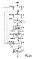
- the functional diagram of figure 2 shows a part of the program contained in the read only memory 9, namely that part of the program that handles the horizontal synchronization recovery in the locked state.
- the catching state is handled in another part of the program (not shown) which gives a first estimation of the location of the horizontal synchronization pulse and of the expected line length. This can be done e.g. by applying a minimum segment sum method. This method implies that the sum of the samples in a segment of for instance 60 samples is calculated. Then the segment is shifted by one sample and the sum is again calculated, etcetera. When the sum is minimal a synchronization pulse is assumed.
- predetermined preferred values for processing a standard interlaced 50 Hz, 625 lines PAL-TV signal are given. However these values should be considered merely as examples. In the actual source-code used by the applicant these values are represented by named constants or variables so that they may be easily changed e.g. in the case that a different TV-standard has to be processed.
- a first program-module M1 which is called “lpf", receives the signal-samples which are contained in the linear array CVBS[].
- This array may comprise e.g. 2500 array-elements for storing part of the received CVBS-signal.
- the program-module M1 performs the following functions:
- a second program-module M2 receives the y-samples derived in module M1 and a variable "slice_est" representing the estimated slice level.
- This slice level lies (preferably halfway) between black level and tap-sync level and is calculated during the preceding execution cycle of the program in a manner described below in connection with the program-modules M4 and M5.
- the purpose of the coincidence module is to ascertain wether indeed a horizontal sync-pulse is present at the expected position (between the samples 12 and 36) in the y[]-array.
- the module compares the value of the y-samples 0-5, 19-30, and 43-48 with the estimated slice level given by the variable "slice_est".
- the decision making module M3 checks whether a variable "ll_est", calculated during earlier execution of the program and which represents the estimated line length (in CVBS-samples) between two consecutive horizontal sync-pulses, is below a maximum acceptable line length value of 940. If the coincidence condition or the line-length condition is not met the program will check inter alia whether a vertical sync-pulse is present and will then enter the part of the program handling vertical synchronization recovery or will else return to the catching mode.
- a program module M4 "slice_black_level_detect”. This module calculates the top-sync level which is the mean value of the y-samples 16-31 (which all lie within the sync-pulse) and the black level which is the mean value of the y-samples 59-75 (which all lie on the back porch of the sync-pulse).
- the black level is stored in a variable "black_calc”.
- the halfway value between black level and top-sync level is calculated and stored as slice level in a variable named "slice_calc”.
- the program enters into a software implementation of a phase locked loop comprising a phase detector module M6, a loop filter module M9 and an oscillator module M10.
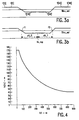
- the phase detector module M6 performs the following actions which are elucidated with the aid of figure 3b:
- a decision making statement M8 compares this phase difference with a predetermined threshold (of e.g. 5 y-samples) and when the phase difference is below this threshold the program will continue with the loop filter module M9.
- program module M9 starts with calculating the line length and separately filters the phase difference and the line length.
- ll_est represents the calculated and filtered line length of the previous line
- dphi_calc is the calculated phase difference between the expected (hs_exp) and the measured centre of the sync pulse currently under investigation
- dphi_calc1 is the phase difference calculated during the preceding execution of the program.
- the loop filter module M9 of figure 2 contains a function "ll_filter” for filtering the calculated line length "ll_calc” and outputting the filtered line length "ll_est”. Furthermore it contains a function “dphi_filter” for filtering the calculated phase difference "dphi_calc” and outputting the filtered phase difference "dphi_est”.
- H ( z ) C * 1- ⁇ 1- ⁇ z -1 n wherein C is a constant and n is a positive integer.
- n is a positive integer.
- H ( Z ) 1- ⁇ 1- ⁇ z -1 2
- f H is the line frequency of for example 15625 Hz in the PAL B-standard.
- a usual value of the -3db bandwidth of a PLL-filter for H-sync recovery is about 200 Hz.
- Low frequency errors would pass easily through the filter resulting in a fluctuating horizontal scan and in a correspondingly unquiet picture.
- the bandwidth is made much smaller it would take too much time for the system to acquire the correct synchronization. Therefore the choice of the loop filter bandwidth is clearly a matter of compromise.
- the bandwidth of the line length filter is made dependent an a "convergence"-counter "lcll". This counter increments each time a predetermined degree of synchronization exists.
- TR1 is chosen at 800 lines in order to more clearly show the horizontal parts for lcll ⁇ 25 and lcll > 800.
- the bandwidth f c is then 39.52 Hz.
- the upper threshold "TR1" may be as large as 10,000 giving a final bandwidth of 3.92 Hz. With this low bandwidth the synchronization is very robust.
- Table 1 shows the program-function "ll_filter” in C-code. Those who are acquainted with C-code will easily understand the operation of this function.
- the table shows line numbers which are not part of the C-code but which are inserted for easy reference.
- Lines 1-6 of table 1 contain the definition of the constants and lines 8-9 the declaration of the global variables so far as used in the function "ll_filter”.
- Lines 11-38 contain the proper function "ll_filter”.
- Line 40 shows the statement which is part of the main program and by which the function "ll_filter” is called.
- the counter "lcll” is increased by 1 each time the function is called until the value of TR1 is reached. Further in these lines the value of the variable "alpha" is calculated in dependence on the value of counter "lcll” and in accordance with formulae IV-VI.
- the filtered line length value is stored in the local variable "rval”, returned by the function "ll_filter” in line 37 of the table and transferred to the global variable "ll_est” in line 40 of the table.
- the calculated slice level "slice_calc” and the calculated black level “black_calc” are both filtered in program module M5.
- the black level filter and the slice level filter have the same z-transform as the line length filter (formula II).
- the counter "lcll” calculated in the function "ll_filter” is also used to reduce the bandwidth of these two filters.
- the only difference between the line length filter and the black-level and slice level filters is that the constant "CONV" in the last two filters is greater (0,25) than in the first filter (0,04). The greater this constant is the greater is the bandwidth-reduction which is obtained with the control by the counter "lcll".
- the loop filter module M9 also contains a filter for the calculated phase difference "dphi_calc”.
- This filter may also be a recursive second order digital filter with a z-transform as given in formula II and which is similarly controlled by the counter "lcll” so that the phase locked loop may become still more stable and less affected by input distortions the longer a proper synchronization exists i.e. the more the synchronization is reliable.
- this "dphi_filter” a more simple solution is available.
- the bandwidth of a phase locked loop depends on the bandwidth of the loop filter, but also on its loop gain, in other words the bandwidth of a phase locked loop may be reduced by reducing the bandwidth of the loop filter but may also be reduced by reducing the loop gain.
- the loop gain is reduced the coupling between received input signal and oscillator becomes looser so that noise and other disturbances present in the input signal have lesser effect on the operation of the oscillator; on the other hand more time is needed for the oscillator to become synchronized.
- the loop filter bandwidth is reduced as when the loop gain is reduced.
- the function "dphi_filter” may be a filter similar to the "ll_filter", however it is more convenient to use for the “dphi_filter” an "lcll”-controlled attenuator.
- Table 2 gives an example of a C-code for this function.
- lines 1 to 6 contain the global constants and variables used in the function
- lines 8 to 23 contain the proper "dphi_filter”-function and line 25 the function call.
- the variable "alpha" is increased linearly with the counter "lcll”.
- the phase difference "dphi_calc” is attenuated by 1/(alpha+1). This implies that, when the counter "lcll” has reached its maximum value TR1 only 1/8979 part of the calculated phase difference "dphi_calc” is transferred as "dphi_est" to the oscillator module M10.
- Figure 2 further shows in program module M9, although strictly speaking not part of the phase locked loop, a function "phi_filter” for filtering a variable "phi_calc” which is the calculated average of phi_0 and phi_1. Because phi_0 + phi_1 is the calculated width of the current synchronization pulse in the y[]-array, the variable “phi_calc” represents the calculated half-width of this pulse. This variable is filtered in the function "phi_filter” to reduce noise and other disturbances. In practice the function "phi_filter” was identical to and was identically controlled by counter “lcll” as the above described slice level and black level filters.
- the oscillator module M10 shows the two following statements:
- the program does not execute the described loop filter module M9 but passes through modules M9a, M10a and M11a, so that the apparently erroneous values of phi_0, phi_1 and dphi_calc are not further used. Instead the original values of ll_est, dpi_est and phi_est, found during the preceding execution cycle, are again used to create new values of hs_est and hs_exp in module M10a which comprise the same statements as module M10. In module M9a the convergence counter lcll is reduced by 1.
- module M10a After the execution of module M10a the program executes module M11a which is identical with module M11 except in that the variable "dpi_calc1" is not made equal to the (erroneous) value of "dpbi_calc” but is set to zero instead.
Landscapes
- Engineering & Computer Science (AREA)
- Multimedia (AREA)
- Signal Processing (AREA)
- Synchronizing For Television (AREA)
- Stabilization Of Oscillater, Synchronisation, Frequency Synthesizers (AREA)
- Television Signal Processing For Recording (AREA)
- Synchronisation In Digital Transmission Systems (AREA)
Claims (14)
- Verfahren zum Wiedergewinnen der Horizontal-Synchronisation aus einem empfangenen Fernsehsignal mit Hilfe einer phasenverriegelten Schleife, wobei dieses Verfahren die nachfolgenden Verfahrensschritte umfasst: das Erzeugen eines wiederkehrenden Oszillatorsignals, das Phasenvergleichen des genannten Oszillatorsignals mit Horizontal-Synchronimpulsen des genannten empfangenen Fernsehsignals, das Tiefpassfiltern des Ergebnisses des Phasenvergleichens und das Benutzen des gefilterten Ergebnisses des Phasenvergleichens zum Steuern der Erzeugung des Oszillatorsignals zum Reduzieren des Phasenfehlers zwischen dem Oszillatorsignal und den Horizontal-Synchronimpulsen des empfangenen Fernsehsignals, gekennzeichnet durch den Schritt, in dem die Anzahl Perioden gezählt werden, in denen es einen vorbestimmten Grad an Synchronisation zwischen dem genannten Oszillatorsignal (hs_exp) und den Horizontal-Synchronimpulsen des empfangenen Fernsehsignals gibt und den Schritt der Steuerung einer Bandbreite der genannten phasenverriegelten Schleife in Reaktion auf das Ergebnis (1cll) des genannten Zählvorgangs zum progressiven Reduzieren der genannten Bandbreite, wenn die genannte Anzahl Perioden zunimmt.
- Verfahren nach Anspruch 1, gekennzeichnet durch die nachfolgenden Verfahrensschritte: die Verwendung des Ergebnisses (dphi_calc) des Phasenvergleichs zum Erzeugen eines Signals (ll_calc), das indikativ ist für die Länge der Periode des genannten Oszillatorsignals, die Tiefpassfilterung des auf diese Art und Weise erhaltenen für die Länge indikativen Signals und die Benutzung des gefilterten längenidikativen Signals (ll_est) zur Steuerung der Erzeugung des genannten Oszillatorsignals (hs_exp), wodurch die Bandbreite (fc) der Tiefpassfilterung durch das Ergebnis (1cll) der genannten Zählung gesteuert wird.
- Verfahren nach Anspruch 2, dadurch gekennzeichnet, dass die Null-Frequenzübertragung der Tiefpassfilterung des längenindikativen Signals nicht beeinträchtigt wird aus der Steuerung der Bandbreite.
- Verfahren nach Anspruch 3, dadurch gekennzeichnet, dass die Tiefpassfilterung des längenindikativen Signals (ll_calc) eine digitale Filterung ist mit einer z-Transformationsfunktion
- Verfahren nach Anspruch 2, wobei das Ergebnis (dphi_calc) des Phasenvergleichs benutzt wird zum zusätzlichen Steuern der Phase des genannten Oszillatorsignals, dadurch gekennzeichnet, dass das Ergebnis der Zählung die genannte Phasensteuerung steuert.
- Verfahren nach Anspruch 5, dadurch gekennzeichnet, dass das Ergebnis (1cll) der Zählung die Phasensteuerung des Oszillatorsignals progressiv dämpft, wenn die genannte Anzahl Perioden zunimmt.
- Verfahren nach Anspruch 1, dadurch gekennzeichnet, dass die Bandbreite der genannten phasenverriegelten Schleife während einer ersten Anzahl (≤ TR0) der genannten Perioden auf einem bestimmten Pegel konstant gehalten wird, während einer zweiten Anzahl Perioden (TR0 → TR1) in Richtung eines niedrigeren Pegels progressiv reduziert wird, und wenn die Anzahl Perioden die genannte zweite Anzahl (≥ TR1) übersteigt, wieder auf einem niedrigeren Pegel konstant gehalten wird.
- Verfahren nach Anspruch 1, dadurch gekennzeichnet, dass die Bandbreite der phasenverriegelten Schleife vergrößert wird, wenn es den vorbestimmten Grad an Synchronisation nicht länger gibt.
- Verfahren nach Anspruch 1, gekennzeichnet durch Detektion eines Scheibenpegels (slice_calc) aus dem empfangenen Fernsehsignal, durch Tiefpassfilterung des Scheibenpegels, durch Verwendung des gefilterten Scheibenpegels (slice_est) in dem Phasenvergleich zwischen dem genannten Oszillatorsignal und den Horizontal-Synchronimpulsen des empfangenen Fernsehsignals, wobei das Ergebnis (1cll) der Zählung außerdem die Bandbreite der Scheibenpegelfilterung (slice_black_filter) steuert zur progressiven Reduktion dieser Bandbreite, wenn die genannte Anzahl Perioden zunimmt.
- Anordnung zum Wiedergewinnen der Horizontal-Synchronisation aus einem empfangenen Fernsehsignal mit Hilfe einer phasenverriegelten Schleife, wobei die genannte Anordnung Mittel aufweist zum Durchführen der nachfolgenden Verfahrensschritte: das Erzeugen eines wiederkehrenden Oszillatorsignals, das Phasenvergleichen des genannten Oszillatorsignals mit Horizontal-Synchronimpulsen des genannten empfangenen Fernsehsignals, das Tiefpassfiltern des Ergebnisses des Phasenvergleichens und das Benutzen des gefilterten Ergebnisses des Phasenvergleichens zum Steuern der Erzeugung des Oszillatorsignals zum Reduzieren des Phasenfehlers zwischen dem Oszillatorsignal und den Horizontal-Synchronimpulsen des empfangenen Fernsehsignals, gekennzeichnet durch den Schritt, in dem die Anzahl Perioden gezählt werden, in denen es einen vorbestimmten Grad an Synchronisation zwischen dem genannten Oszillatorsignal (hs_exp) und den Horizontal-Synchronimpulsen des empfangenen Fernsehsignals gibt und den Schritt der Steuerung einer Bandbreite der genannten phasenverriegelten Schleife in Reaktion auf das Ergebnis (1cll) des genannten Zählvorgangs zum progressiven Reduzieren der genannten Bandbreite, wenn die genannte Anzahl Perioden zunimmt.
- Anordnung nach Anspruch 10, gekennzeichnet durch die tatsache, dass sie einen digitalen Signalprozessor (5) sowie einen Speicher (9) mit einem gespeicherten Programm zur Steuerung der Wirkung der Anordnung umfasst.
- Speichermedium mit einem gespeicherten Programm zur Steuerung der Wirkung eines Signalprozessors zum Wiederherstellen der Horizontal-Synchronisation aus einem empfangenen Fernsehsignal mit Hilfe einer phasenverriegelten Schleife, wobei diese genannte Wiederherstellung die nachfolgenden Verfahrensschritte umfasst: das Erzeugen eines wiederkehrenden Oszillatorsignals, das Phasenvergleichen des genannten Oszillatorsignals mit Horizontal-Synchronimpulsen des genannten empfangenen Fernsehsignals, das Tiefpassfiltern des Ergebnisses des Phasenvergleichens und das Benutzen des gefilterten Ergebnisses des Phasenvergleichens zum Steuern der Erzeugung des Oszillatorsignals zum Reduzieren des Phasenfehlers zwischen dem Oszillatorsignal und den Horizontal-Synchronimpulsen des empfangenen Fernsehsignals, wobei die genannte Wiederherstellung gekennzeichnet ist durch den Schritt, in dem die Anzahl Perioden gezählt werden, in denen es einen vorbestimmten Grad an Synchronisation zwischen dem genannten Oszillatorsignal (hs_exp) und den Horizontal-Synchronimpulsen des empfangenen Fernsehsignals gibt und den Schritt der Steuerung einer Bandbreite der genannten phasenverriegelten Schleife in Reaktion auf das Ergebnis (1cll) des genannten Zählvorgangs zum progressiven Reduzieren der genannten Bandbreite, wenn die genannte Anzahl Perioden zunimmt.
- Signal mit einem Programm zum Steuern der Wirkung eines Signalprozessors zum Wiederherstellen der Horizontal-Synchronisation aus einem empfangenen Fernsehsignal mit Hilfe einer phasenverriegelten Schleife, wobei das Programm die nachfolgenden Verfahrensschritte umfasst: das Erzeugen eines wiederkehrenden Oszillatorsignals, das Phasenvergleichen des genannten Oszillatorsignals mit Horizontal-Synchronimpulsen des genannten empfangenen Fernsehsignals, das Tiefpassfiltern des Ergebnisses des Phasenvergleichens und das Benutzen des gefilterten Ergebnisses des Phasenvergleichens zum Steuern der Erzeugung des Oszillatorsignals zum Reduzieren des Phasenfehlers zwischen dem Oszillatorsignal und den Horizontal-Synchronimpulsen des empfangenen Fernsehsignals, wobei das genannte Programm gekennzeichnet ist durch den Schritt, in dem die Anzahl Perioden gezählt werden, in denen es einen vorbestimmten Grad an Synchronisation zwischen dem genannten Oszillatorsignal (hs_exp) und den Horizontal-Synchronimpulsen des empfangenen Fernsehsignals gibt und den Schritt der Steuerung einer Bandbreite der genannten phasenverriegelten Schleife in Reaktion auf das Ergebnis (1cll) des genannten Zählvorgangs zum progressiven Reduzieren der genannten Bandbreite, wenn die genannte Anzahl Perioden zunimmt.
- Wiedergabeanordnung, welche die nachfolgenden Elemente umfasst:eine Wiedergabeanordnung mit einem Wiedergabeschirm,eine Anordnung zum Wiederherstellen der Horizontal-Synchronisation aus einem empfangenen Fernsehsignal mit Hilfe einer phasenverriegelten Schleife, wobei diese Wiederherstellungsanordnung Mittel aufweist zum Erzeugen eines wiederkehrenden Oszillatorsignals, Mittel zum Phasenvergleichen des genannten Oszillatorsignals mit Horizontal-Synchronimpulsen des genannten empfangenen Fernsehsignals, Mittel zum Tiefpassfiltern des Ergebnisses des Phasenvergleichens und Mittel zum Benutzen des gefilterten Ergebnisses des Phasenvergleichens zum Steuern der Erzeugung des Oszillatorsignals zum Reduzieren des Phasenfehlers zwischen dem Oszillatorsignal und den Horizontal-Synchronim-pulsen des empfangenen Fernsehsignals, und Mittel zum Liefern von Horizontal-Abtastinformation, die zu dem Oszillatorsignal in einem bestimmten Verhältnis steht, undeine Adressierungseinheit, welche die Horizontal-Abtastinformation empfängt zum bestimmen einer horizontalen Position des Fernsehsignals am Wiedergabeschirm, dadurch gekennzeichnet, dass die Wiedergabeanordnung weiterhin die nachfolgenden Elemente umfasst:Mittel zum Zählen der Anzahl Perioden, in denen es einen vorbestimmten Grad an Synchronisation zwischen dem genannten Oszillatorsignal (hs_exp) und den Horizontal-Synchronimpulsen des empfangenen Fernsehsignals gibt undMittel zum Steuern einer Bandbreite der genannten phasenverriegelten Schleife in Reaktion auf das Ergebnis (lcll) der genannten Zählung zum progressiven Reduzieren der genannten Bandbreite, wenn die genannte Anzahl Perioden zunimmt.
Priority Applications (1)
| Application Number | Priority Date | Filing Date | Title |
|---|---|---|---|
| EP97920912A EP0842583B1 (de) | 1996-06-06 | 1997-05-27 | Wiedergewinnung der horizontalen synchronisation |
Applications Claiming Priority (4)
| Application Number | Priority Date | Filing Date | Title |
|---|---|---|---|
| EP96201562 | 1996-06-06 | ||
| EP96201562 | 1996-06-06 | ||
| EP97920912A EP0842583B1 (de) | 1996-06-06 | 1997-05-27 | Wiedergewinnung der horizontalen synchronisation |
| PCT/IB1997/000601 WO1997047134A1 (en) | 1996-06-06 | 1997-05-27 | Recovering horizontal synchronization |
Publications (2)
| Publication Number | Publication Date |
|---|---|
| EP0842583A1 EP0842583A1 (de) | 1998-05-20 |
| EP0842583B1 true EP0842583B1 (de) | 2002-05-02 |
Family
ID=8224050
Family Applications (1)
| Application Number | Title | Priority Date | Filing Date |
|---|---|---|---|
| EP97920912A Expired - Lifetime EP0842583B1 (de) | 1996-06-06 | 1997-05-27 | Wiedergewinnung der horizontalen synchronisation |
Country Status (8)
| Country | Link |
|---|---|
| US (1) | US5953071A (de) |
| EP (1) | EP0842583B1 (de) |
| JP (1) | JPH11510988A (de) |
| KR (1) | KR100513413B1 (de) |
| CN (1) | CN1179514C (de) |
| DE (1) | DE69712291T2 (de) |
| MY (1) | MY132377A (de) |
| WO (1) | WO1997047134A1 (de) |
Families Citing this family (14)
| Publication number | Priority date | Publication date | Assignee | Title |
|---|---|---|---|---|
| JPH11355603A (ja) * | 1998-06-09 | 1999-12-24 | Fuji Film Microdevices Co Ltd | 水平同期検出回路 |
| US6912012B2 (en) * | 2001-07-20 | 2005-06-28 | Texas Instruments Incorporated | Video decoder having lock algorithm that distinguishes between a noisy television signal input and a video recorder signal |
| US7520853B2 (en) * | 2001-12-28 | 2009-04-21 | Karl Storz Imaging, Inc. | Updateable endoscopic video imaging system |
| US7434113B2 (en) * | 2002-09-30 | 2008-10-07 | Lecroy Corporation | Method of analyzing serial data streams |
| US7437624B2 (en) * | 2002-09-30 | 2008-10-14 | Lecroy Corporation | Method and apparatus for analyzing serial data streams |
| US7519874B2 (en) | 2002-09-30 | 2009-04-14 | Lecroy Corporation | Method and apparatus for bit error rate analysis |
| US7365796B1 (en) | 2003-05-20 | 2008-04-29 | Pixelworks, Inc. | System and method for video signal decoding using digital signal processing |
| US7304688B1 (en) | 2003-05-20 | 2007-12-04 | Pixelworks, Inc. | Adaptive Y/C separator |
| US7701512B1 (en) | 2003-05-20 | 2010-04-20 | Pixelworks, Inc. | System and method for improved horizontal and vertical sync pulse detection and processing |
| US7532254B1 (en) | 2003-05-20 | 2009-05-12 | Pixelworks, Inc. | Comb filter system and method |
| US7420625B1 (en) | 2003-05-20 | 2008-09-02 | Pixelworks, Inc. | Fuzzy logic based adaptive Y/C separation system and method |
| US7605867B1 (en) * | 2003-05-20 | 2009-10-20 | Pixelworks, Inc. | Method and apparatus for correction of time base errors |
| CN100579173C (zh) * | 2004-03-30 | 2010-01-06 | 松下电器产业株式会社 | 图像信号数据发生器 |
| US8212941B2 (en) * | 2008-04-30 | 2012-07-03 | Mediatek Inc. | Digitized analog TV signal processing system |
Family Cites Families (9)
| Publication number | Priority date | Publication date | Assignee | Title |
|---|---|---|---|---|
| JPS5242492B2 (de) * | 1972-10-09 | 1977-10-25 | ||
| US3909735A (en) * | 1974-04-04 | 1975-09-30 | Ncr Co | Slow switch for bandwidth change in phase-locked loop |
| US4348694A (en) * | 1980-12-29 | 1982-09-07 | Motorola, Inc. | Horizontal phase detector gain control |
| US4535358A (en) * | 1982-04-13 | 1985-08-13 | U.S. Philips Corporation | Line synchronizing circuit for a picture display devices and picture display device comprising such a circuit |
| US4928075A (en) * | 1989-06-26 | 1990-05-22 | Digital Equipment Corporation | Multiple bandwidth filter system for phase locked loop |
| US5182761A (en) * | 1991-01-31 | 1993-01-26 | Motorola, Inc. | Data transmission system receiver having phase-independent bandwidth control |
| US5155595A (en) * | 1991-01-31 | 1992-10-13 | Lsi Logic Corp. | Genlock frequency generator |
| JPH06334894A (ja) * | 1993-05-19 | 1994-12-02 | Toshiba Corp | 水平同期装置 |
| US5534823A (en) * | 1994-02-28 | 1996-07-09 | Nec Corporation | Phase locked loop (PLL) circuit having variable loop filter for shortened locking time |
-
1997
- 1997-05-27 EP EP97920912A patent/EP0842583B1/de not_active Expired - Lifetime
- 1997-05-27 WO PCT/IB1997/000601 patent/WO1997047134A1/en not_active Ceased
- 1997-05-27 KR KR1019980700886A patent/KR100513413B1/ko not_active Expired - Fee Related
- 1997-05-27 CN CNB971909520A patent/CN1179514C/zh not_active Expired - Fee Related
- 1997-05-27 DE DE69712291T patent/DE69712291T2/de not_active Expired - Fee Related
- 1997-05-27 JP JP10500366A patent/JPH11510988A/ja active Pending
- 1997-06-04 US US08/869,263 patent/US5953071A/en not_active Expired - Fee Related
- 1997-06-04 MY MYPI97002488A patent/MY132377A/en unknown
Also Published As
| Publication number | Publication date |
|---|---|
| JPH11510988A (ja) | 1999-09-21 |
| DE69712291D1 (de) | 2002-06-06 |
| KR19990036218A (ko) | 1999-05-25 |
| CN1179514C (zh) | 2004-12-08 |
| DE69712291T2 (de) | 2002-12-05 |
| KR100513413B1 (ko) | 2006-02-28 |
| CN1198287A (zh) | 1998-11-04 |
| MY132377A (en) | 2007-10-31 |
| WO1997047134A1 (en) | 1997-12-11 |
| US5953071A (en) | 1999-09-14 |
| EP0842583A1 (de) | 1998-05-20 |
Similar Documents
| Publication | Publication Date | Title |
|---|---|---|
| EP0842583B1 (de) | Wiedergewinnung der horizontalen synchronisation | |
| CN1164796A (zh) | 图像信号处理装置 | |
| US4573080A (en) | Progressive scan television receiver with adaptive memory addressing | |
| JPH06233156A (ja) | Tv受信機あるいはビデオレコーダに使用されるゴースト消去基準信号捕捉回路 | |
| US4680632A (en) | Television display system with flicker reduction processor having burst locked clock and skew correction | |
| US4667240A (en) | Timing correction circuitry as for TV signal recursive filters | |
| JPS5856593A (ja) | 信号振幅比調整回路 | |
| JP2972178B2 (ja) | フレーム同期装置及びその方法 | |
| EP0899945A2 (de) | Verfahren und Vorrichtung zur Gewinnung von Zeilensynchronisations-Informationsposten aus einem Videosignal | |
| US20020047924A1 (en) | Method and apparatus for recovering video color subcarrier signal | |
| EP0449501A2 (de) | Zeitbasiskorrigierer | |
| JP3092938B2 (ja) | 画像表示装置用ディジタル同期回路 | |
| EP1405503B1 (de) | Verfahren zum erlangen von zeilensynchronisationsinformationsobjekten von einen videosignal und vorrichtung zur durchführung des verfahrens | |
| US4897713A (en) | Color television signal decoding circuit | |
| JP2627270B2 (ja) | 復調位相誤差を減じるための回路 | |
| CN1033781C (zh) | 时基误差校正器基准信号的记录/重放电路 | |
| JPH07312699A (ja) | ディジタル映像再生装置 | |
| JP3599253B2 (ja) | Pal/secam信号判別回路およびテレビジョン信号受信装置 | |
| Rothermel et al. | Synchronization of analog video signals with improved image stability | |
| JPH10164618A (ja) | 映像信号処理回路 | |
| JPS61161092A (ja) | デイジタルテレビジヨン受像機 | |
| KR980013455A (ko) | 화상 정보 처리 장치(Picture Information Processing Apparatus) | |
| JPH03224382A (ja) | 時間軸誤差補正装置 | |
| JPH0197082A (ja) | 文字放送信号再生装置 |
Legal Events
| Date | Code | Title | Description |
|---|---|---|---|
| PUAI | Public reference made under article 153(3) epc to a published international application that has entered the european phase |
Free format text: ORIGINAL CODE: 0009012 |
|
| AK | Designated contracting states |
Kind code of ref document: A1 Designated state(s): DE FR GB |
|
| 17P | Request for examination filed |
Effective date: 19980612 |
|
| GRAG | Despatch of communication of intention to grant |
Free format text: ORIGINAL CODE: EPIDOS AGRA |
|
| 17Q | First examination report despatched |
Effective date: 20010709 |
|
| GRAG | Despatch of communication of intention to grant |
Free format text: ORIGINAL CODE: EPIDOS AGRA |
|
| GRAH | Despatch of communication of intention to grant a patent |
Free format text: ORIGINAL CODE: EPIDOS IGRA |
|
| REG | Reference to a national code |
Ref country code: GB Ref legal event code: IF02 |
|
| GRAH | Despatch of communication of intention to grant a patent |
Free format text: ORIGINAL CODE: EPIDOS IGRA |
|
| GRAA | (expected) grant |
Free format text: ORIGINAL CODE: 0009210 |
|
| AK | Designated contracting states |
Kind code of ref document: B1 Designated state(s): DE FR GB |
|
| REG | Reference to a national code |
Ref country code: GB Ref legal event code: FG4D |
|
| REF | Corresponds to: |
Ref document number: 69712291 Country of ref document: DE Date of ref document: 20020606 |
|
| ET | Fr: translation filed | ||
| REG | Reference to a national code |
Ref country code: FR Ref legal event code: D6 |
|
| REG | Reference to a national code |
Ref country code: GB Ref legal event code: 746 Effective date: 20021107 |
|
| PLBE | No opposition filed within time limit |
Free format text: ORIGINAL CODE: 0009261 |
|
| STAA | Information on the status of an ep patent application or granted ep patent |
Free format text: STATUS: NO OPPOSITION FILED WITHIN TIME LIMIT |
|
| 26N | No opposition filed |
Effective date: 20030204 |
|
| PGFP | Annual fee paid to national office [announced via postgrant information from national office to epo] |
Ref country code: GB Payment date: 20050518 Year of fee payment: 9 |
|
| PGFP | Annual fee paid to national office [announced via postgrant information from national office to epo] |
Ref country code: FR Payment date: 20050527 Year of fee payment: 9 |
|
| PGFP | Annual fee paid to national office [announced via postgrant information from national office to epo] |
Ref country code: DE Payment date: 20050719 Year of fee payment: 9 |
|
| PG25 | Lapsed in a contracting state [announced via postgrant information from national office to epo] |
Ref country code: GB Free format text: LAPSE BECAUSE OF NON-PAYMENT OF DUE FEES Effective date: 20060527 |
|
| PG25 | Lapsed in a contracting state [announced via postgrant information from national office to epo] |
Ref country code: DE Free format text: LAPSE BECAUSE OF NON-PAYMENT OF DUE FEES Effective date: 20061201 |
|
| GBPC | Gb: european patent ceased through non-payment of renewal fee |
Effective date: 20060527 |
|
| REG | Reference to a national code |
Ref country code: FR Ref legal event code: ST Effective date: 20070131 |
|
| PG25 | Lapsed in a contracting state [announced via postgrant information from national office to epo] |
Ref country code: FR Free format text: LAPSE BECAUSE OF NON-PAYMENT OF DUE FEES Effective date: 20060531 |