EP0841959B1 - Dialysis machine - Google Patents
Dialysis machine Download PDFInfo
- Publication number
- EP0841959B1 EP0841959B1 EP96922362A EP96922362A EP0841959B1 EP 0841959 B1 EP0841959 B1 EP 0841959B1 EP 96922362 A EP96922362 A EP 96922362A EP 96922362 A EP96922362 A EP 96922362A EP 0841959 B1 EP0841959 B1 EP 0841959B1
- Authority
- EP
- European Patent Office
- Prior art keywords
- yaw
- cartridge
- dialysis machine
- lid
- yaws
- Prior art date
- Legal status (The legal status is an assumption and is not a legal conclusion. Google has not performed a legal analysis and makes no representation as to the accuracy of the status listed.)
- Expired - Lifetime
Links
- 238000000502 dialysis Methods 0.000 title claims abstract description 43
- 239000000843 powder Substances 0.000 claims abstract description 32
- 239000007788 liquid Substances 0.000 claims abstract description 25
- 238000006073 displacement reaction Methods 0.000 claims abstract description 3
- 238000007789 sealing Methods 0.000 claims description 30
- 201000009482 yaws Diseases 0.000 claims description 20
- 230000008878 coupling Effects 0.000 claims description 7
- 238000010168 coupling process Methods 0.000 claims description 7
- 238000005859 coupling reaction Methods 0.000 claims description 7
- 230000000694 effects Effects 0.000 claims description 2
- 125000006850 spacer group Chemical group 0.000 claims 2
- XLYOFNOQVPJJNP-UHFFFAOYSA-N water Substances O XLYOFNOQVPJJNP-UHFFFAOYSA-N 0.000 description 15
- 238000011282 treatment Methods 0.000 description 11
- UIIMBOGNXHQVGW-UHFFFAOYSA-M Sodium bicarbonate Chemical compound [Na+].OC([O-])=O UIIMBOGNXHQVGW-UHFFFAOYSA-M 0.000 description 8
- 238000004659 sterilization and disinfection Methods 0.000 description 8
- 239000004743 Polypropylene Substances 0.000 description 6
- -1 polypropylene Polymers 0.000 description 6
- 229920001155 polypropylene Polymers 0.000 description 6
- 238000002347 injection Methods 0.000 description 4
- 239000007924 injection Substances 0.000 description 4
- 239000000463 material Substances 0.000 description 4
- 229910000030 sodium bicarbonate Inorganic materials 0.000 description 4
- 235000017557 sodium bicarbonate Nutrition 0.000 description 4
- 239000012528 membrane Substances 0.000 description 3
- 239000004033 plastic Substances 0.000 description 3
- 229920003023 plastic Polymers 0.000 description 3
- 239000000243 solution Substances 0.000 description 3
- 239000011324 bead Substances 0.000 description 2
- 235000014666 liquid concentrate Nutrition 0.000 description 2
- 238000001556 precipitation Methods 0.000 description 2
- 239000002689 soil Substances 0.000 description 2
- 238000003466 welding Methods 0.000 description 2
- BVKZGUZCCUSVTD-UHFFFAOYSA-M Bicarbonate Chemical compound OC([O-])=O BVKZGUZCCUSVTD-UHFFFAOYSA-M 0.000 description 1
- 230000004323 axial length Effects 0.000 description 1
- 239000002775 capsule Substances 0.000 description 1
- 239000011248 coating agent Substances 0.000 description 1
- 238000000576 coating method Methods 0.000 description 1
- 230000006835 compression Effects 0.000 description 1
- 238000007906 compression Methods 0.000 description 1
- 235000008504 concentrate Nutrition 0.000 description 1
- 239000012141 concentrate Substances 0.000 description 1
- 238000011109 contamination Methods 0.000 description 1
- 230000008021 deposition Effects 0.000 description 1
- 238000011049 filling Methods 0.000 description 1
- 238000003780 insertion Methods 0.000 description 1
- 230000037431 insertion Effects 0.000 description 1
- 238000012423 maintenance Methods 0.000 description 1
- 238000000034 method Methods 0.000 description 1
- 239000002991 molded plastic Substances 0.000 description 1
- 230000000149 penetrating effect Effects 0.000 description 1
- 230000002093 peripheral effect Effects 0.000 description 1
- 235000014483 powder concentrate Nutrition 0.000 description 1
- 238000002360 preparation method Methods 0.000 description 1
- 238000011084 recovery Methods 0.000 description 1
- 230000000284 resting effect Effects 0.000 description 1
- 238000002604 ultrasonography Methods 0.000 description 1
Images


Classifications
-
- A—HUMAN NECESSITIES
- A61—MEDICAL OR VETERINARY SCIENCE; HYGIENE
- A61M—DEVICES FOR INTRODUCING MEDIA INTO, OR ONTO, THE BODY; DEVICES FOR TRANSDUCING BODY MEDIA OR FOR TAKING MEDIA FROM THE BODY; DEVICES FOR PRODUCING OR ENDING SLEEP OR STUPOR
- A61M1/00—Suction or pumping devices for medical purposes; Devices for carrying-off, for treatment of, or for carrying-over, body-liquids; Drainage systems
- A61M1/14—Dialysis systems; Artificial kidneys; Blood oxygenators ; Reciprocating systems for treatment of body fluids, e.g. single needle systems for hemofiltration or pheresis
- A61M1/16—Dialysis systems; Artificial kidneys; Blood oxygenators ; Reciprocating systems for treatment of body fluids, e.g. single needle systems for hemofiltration or pheresis with membranes
- A61M1/1654—Dialysates therefor
- A61M1/1656—Apparatus for preparing dialysates
- A61M1/1666—Apparatus for preparing dialysates by dissolving solids
-
- A—HUMAN NECESSITIES
- A61—MEDICAL OR VETERINARY SCIENCE; HYGIENE
- A61M—DEVICES FOR INTRODUCING MEDIA INTO, OR ONTO, THE BODY; DEVICES FOR TRANSDUCING BODY MEDIA OR FOR TAKING MEDIA FROM THE BODY; DEVICES FOR PRODUCING OR ENDING SLEEP OR STUPOR
- A61M1/00—Suction or pumping devices for medical purposes; Devices for carrying-off, for treatment of, or for carrying-over, body-liquids; Drainage systems
- A61M1/14—Dialysis systems; Artificial kidneys; Blood oxygenators ; Reciprocating systems for treatment of body fluids, e.g. single needle systems for hemofiltration or pheresis
- A61M1/16—Dialysis systems; Artificial kidneys; Blood oxygenators ; Reciprocating systems for treatment of body fluids, e.g. single needle systems for hemofiltration or pheresis with membranes
- A61M1/1654—Dialysates therefor
- A61M1/1656—Apparatus for preparing dialysates
- A61M1/1668—Details of containers
-
- A—HUMAN NECESSITIES
- A61—MEDICAL OR VETERINARY SCIENCE; HYGIENE
- A61M—DEVICES FOR INTRODUCING MEDIA INTO, OR ONTO, THE BODY; DEVICES FOR TRANSDUCING BODY MEDIA OR FOR TAKING MEDIA FROM THE BODY; DEVICES FOR PRODUCING OR ENDING SLEEP OR STUPOR
- A61M2209/00—Ancillary equipment
- A61M2209/08—Supports for equipment
- A61M2209/082—Mounting brackets, arm supports for equipment
Definitions
- the invention relates to a dialysis machine with a device for exchangeable connection of a powder cartridge between an inlet and an outlet for liquid, said device having two jaws one of said jaws being provided with said inlet and the other one of said jaws being provided with said outlet at least one of said jaws being guided for movement towards and away from the other one for engaging the yaws with the powder cartridge under connection of the inlet and the outlet to a hollow stud on the powder cartridge located therebetween for conducting liquid through the cartridge.
- EP-B1 0 278 100 describes a dialysis system wherein the dialysis liquid is prepared at the site of use from a powder (sodium bicarbonate) which is supplied in a closed container - cartridge - which is inserted into a holder on the machine and is connected to an inlet for water and an outlet for the concentrated solution of the powder, which is obtained when water flows through the cartridge and dissolves the powder.
- This liquid concentrate then is added in an accurately measured amount to a water flow in the machine for obtaining dialysis liquid having the required concentration.
- the cartridge is inserted between two yaws pivotally mounted on a vertical wall of the machine one above the other, one of these yaws having an inlet for water and the other an outlet for the liquid concentrate obtained by dissolving the powder in the cartridge when water is allowed to flow through the cartridge. Then, the inlet and the outlet are connected to hollow studs which are provided at the ends of the cartridge. The connection takes place by penetrating membranes which are provided on the hollow studs and close these studs.
- the upper yaw is swung upwards when the cartridge is to be located between the yaws or is to be removed from this position after the powder in the cartridge having been consumed, but the yaws can also be swung towards said wall of the machine, the upper yaw downwards and the lower yaw upwards, in order that the inlet and the outlet, respectively, shall be connected with two connection pieces on the wall which are dimensioned in the same manner as the hollow studs on the cartridge. Between these connection pieces there is provided a short-circuit conduit so that liquid can flow from one yaw to the other via the short-circuit conduit without passing through a cartridge positioned between the yaws. This short-circuit connection is used also when the machine between two dialysis treatments following one upon the other has to be rinsed and disinfected by circulating a flow of disinfection liquid through the machine.
- the purpose of the invention is to eliminate these drawbacks by providing a device of the kind mentioned above which makes possible that the sealing rings which shall seal between the hollow studs of the cartridge and the inlet and the outlet, respectively, are exposed during the rinsing and disinfection cycle to be rinsed and disinfected, and wherein the sealing rings are mounted on the yaws in such a manner that they can be exchanged in a simple manner when required without extensive demounting and mounting work being required.
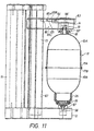
- FIG. 1 in the drawing there is disclosed a dialysis machine 10 which is supposed to be of the type DrakeWillock® system 1000TM and in the present case is set up to operate with preparation of dialysis liquid from a powder concentrate (sodium bicarbonate), which in an amount intended for one or more treatments is enclosed in a disposable cartridge 11.
- This cartridge is mounted to the machine between a stationary lower yaw 12 and a movable upper yaw 14 which can be displaced towards and away from the lower yaw on a tubular guide 13.
- Said guide is supported by an holder 15 which is mounted to a vertical mounting rail 16 provided externally on the machine.
- Means not shown in detail in FIG. 1 are provided for conducting water through the cartridge for dissolving the powder in the water as is known per se in connection with dialysis machines.
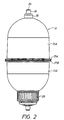
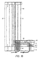
- Cartridge 11, FIGS. 2 and 3 is cylindrical with semi-spherically domed end portions and is made up of two parts 11A and 11B of injection molded plastics, preferably polypropylene, which are interconnected by mirror welding at outwardly projecting circumferential flanges 17A and 17B, respectively.
- One part 11A the upper part, which has a larger axial length than the other part 11B such that the joint between the parts at flanges 17A and 17B is not located midway of the cartridge forms a central circular hollow stud in the domed end, said stud comprising a portion 18 connecting to part 11A and having a larger diameter, and a portion 19 projecting therefrom and having a smaller diameter, the hollow stud thus formed communicating with the interior of the cartridge and being closed at the outer end thereof by means of a membrane 20 formed as an end wall on the stud.
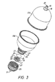
- the other part 11B of the cartridge forms in the domed end thereof a central circular neck 21 having an external screw thread 22.
- the neck joins a circular axially directed collar 23 which has internally a smooth cylindrical surface 24 and has externally a circumferential row of a saw teeth 25.
- a cap 26 having a grooved or knurled outside surface and internal screw threads 27 is dimensioned to be screwed onto the neck and has an end wall 28 which is connected with the rest of the cap by means of a number of shear webs 29 distributed over the circumference of the cap a small slit or cut 30 being provided between the end wall and the rest of the cap said slit or cut being bridged by the shear webs 29.
- the cap with end wall 28 and shear webs 29 is injection molded in one piece of plastics, preferably the same plastics as that the cartridge is made of, viz. polypropylene.
- End wall 28 forms a circular hollow stud 31 projecting centrally from said end wall said stud being closed in the outer end thereof by means of a membrane 32 forming an end wall of the stud.
- End wall 28 has internally a circular row of saw teeth 33 which are, however, inclined in the opposite direction to teeth 25 on the neck. Moreover, end wall 28 forms an internal annular bulge 34 having an outwardly directed cylindrical surface 35.
- a valve element 36 is mounted on bulge 34 said valve element comprising a circular ring 37 with a cylindrical axially directed collar 38. This collar is so dimensioned that it fits on the inside thereof against surface 35, and it has on the inside an annular bead 39 which snaps into an annular groove in surface 35 when the valve element is mounted on bulge 34 in the correct position thereof.
- the valve element comprises also a valve member 40 which is cylindrical but at a conical portion 41 merges from a portion 42 having a larger diameter, into a portion 43 having a smaller diameter, said latter portion having an outside diameter which is smaller than the inside diameter of hollow stud 31 so that portion 43 can project into said stud, and terminates at an end wall 44 at the lower end of the valve member.
- the valve member is connected with ring 37 by means of four thin resiliently flexible arms 45 so that the valve member 40 can be moved axially in relation to the ring 37.
- valve element 36 preferably is injection molded of polypropylene.
- a woven or injection molded filter net 46 also preferably of polypropylene is located in a recess in the upper surface of ring 37 and is connected to the ring by ultrasound welding.
- Neck 21 has a radial flange 48 which at a flared edge portion 49 sealingly engages the upper surface of filter net 46 in the peripheral region thereof and also serves to locate valve element 36 in the cap when it is screwed on. Just before the cap is completely screwed on teeth 25 and 33 will interengage but these teeth shall be so orientated that they allow the cap to be screwed on, the teeth 33 of the cap rasping over teeth 25 on the neck without engaging therewith. The cartridge is then completely closed for storage and transport until it is connected to the dialysis machine. -All parts of the cartridge including the net, valve element and cap, should be made of one and the same plastics and as ' mentioned above a suitable material is polypropylene.
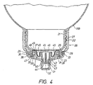
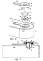
- the stationary yaw 12 is provided with a bushing 50 which is inserted into an aperture 51 in the yaw and at a shoulder formed by an outside flange 52 on the bushing rests on the upper surface of the yaw.
- a gasket in the shape of an O-ring 54 is located, and on flange 52 a further gasket in the shape of an O-ring 55 is located.
- a tube 56 which can be attached to the bushing or be integral therewith.
- the upper end of the tube is made tapering by being obliquely cut off similar to a cannula while the lower end of the tube is adapted to be connected to a hose.
- a lid 57 having a central opening 58 is provided over bushing 50 and is mounted to yaw 12 by means of bayonet coupling means 59 for engagement into matching slots 59A in the yaw.
- An arm 57A with a projection 57B on the lower side thereof is provided on lid 57, and when the lid has been located and the bayonet coupling has been engaged by turning the lid projection 57B is received in a depression 60 in the yaw.
- Arm 57A is sufficiently resilient so that projection 57B when the lid is being rotated in order to disengage the bayonet coupling can slide on the upper surface of the yaw and then snap into the depression 60 when the lid is locked in position. Lid 57 maintains O-rings 54 and 55 in position in the yaw.
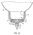
- the upper yaw has a similar arrangement; earlier described elements have been given corresponding reference numbers with the addition of a prime sign.
- a ring 61 and a seal in the shape of an O-ring 62 Lid 57' which in this case has a larger diameter than lid 57 on the lower yaw keeps ring 61 pressed against the yaw while the ring in turn maintains bushing 50' in opening 51' and also maintains O-rings 54' and 55' in position.
- O-ring 62 located between ring 61 and lid 57' is received by ring 61 and is maintained in position by this ring and the lid.
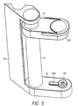
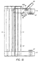
- an operating member 63 On the upper yaw 14 an operating member 63 is provided which can be swung upwards from the position shown in FIGS. 5 to 8 about an horizontal shaft 64 to the position shown in FIG. 10.
- the operating member is rigidly connected with a lever 65 inside yaw 14.
- the free end of lever 65 engages a notch 66 in guide 13; see FIG. 11.
- yaw 14 is kept in the position shown in FIG. 11.
- the operating member is arrested in this position by means of a protrusion 65A on the yaw, which engages a depression 65B on arm 65.
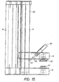
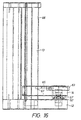
- yaw 14 When the operating member 63 is swung upwards yaw 14 will initially be moved two cm or so upwards along guide 13 by means of lever 65 engaging notch 66 said notch 66 in guide 13 forming an abutment for the yaw to be raised. If the operating member 63 is swung further upwards to the position according to FIG. 10 wherein the operating member is arrested by another protrusion 65C on yaw 14 engaging depression 65B, lever 65 will be disengaged from notch 66 and yaw 14 can now be displaced freely downwards along guide 13. When yaw 14 has been displaced downwards towards the stationary yaw 12, FIG. 15, it will be in a lower position, FIG. 16, when the operating member 63 is folded down with lever 65 engaging a notch 67 in guide 13.
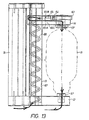
- An helical hose 68, FIGS. 13 and 14, which is located in the tubular guide 13 is, at the ends thereof, anchored to the lower and the upper yaw 12 and 14, respectively, and communicates below with a water conduit (not shown) in the dialysis machine 10 and at the top with tube 56' in the upper yaw 14 for supply of water to said tube 46' while another hose (not shown) is connected to tube 56 in the lower yaw 12 to be connected to the dialysis machine at a position where concentrated sodium bicarbonate solution shall be supplied for use in the dialysis machine.
- the cartridge 11 described filled with powder and closed by means of capsule 26 is mounted between yaws 12 and 14 as shown in FIG. 11 and indicated by dot-and-dash lines in FIG. 13 in the following manner.
- the upper yaw 14 is displaced upwards two cm or so by the operating member 63 being swung upwards, FIG. 10, and with the upper yaw in this position cartridge 11 at stud 31 on screw cap 26 is passed through the central opening in lid 57 on the lower yaw 12 and into socket 50.
- O-ring 54 will seal around stud 31.
- the pointed end of tube 56 is moved against end wall 32 and sufficient pressure is exerted on the cartridge in order that this end wall will be penetrated and will yield.
- the end wall has a circular shear line in order to be folded upwards as a pivoted lid when tube 56 is pressed against the end wall as is indicated in FIG. 4 by dot-and-dash lines.
- Tube 56 has such length that when screw cap 26 engages lid 57 on the lower yaw 12 the tube engages valve member 40 and has lifted said member from the seat thereof on end wall 28 against the spring bias of arms 45.
- operating member 63 is pressed down towards the position disclosed in FIG. 11 the movable upper yaw 14 being moved downwards receiving portion 19 having the smaller diameter of the hollow stud in the upper end of cartridge 11, in bushing 50' in the upper yaw 14 O-ring 54' sealing around the stud.
- the pointed end of the cannula-like tube 56' will penetrate end wall 20 of the hollow stud.
- Sealing ring 62 is not effective in this position because portion 18 having the larger diameter of the hollow stud in the upper end of the cartridge has a considerably smaller diameter than the central opening in lid 57' on the upper yaw 14.
- the cartridge is mounted between tube 56' on the upper yaw 14 and tube 56 on the lower yaw 12 to conduct water through the cartridge for dissolving the powder enclosed therein into the water for the performance a dialysis treatment.
- the solution discharged from the cartridge is a concentrate which will be diluted with water in the machine to the concentration required for the treatment.
- the liquid flow is disclosed in FIG. 13 where cartridge 11 is indicated with dot-and-dash lines only. However, the arrows in FIG.
- the "used" cartridge When the treatment (or treatments) have been completed the "used" cartridge shall be removed which is effected by displacement of the upper yaw 14 upwards two cm or so by the operating member 63 being swung upwards (FIG. 10). Tube 56' on the upper yaw then will be drawn out of the hollow stud 19 at the upper end of the cartridge which then can be lifted from the lower yaw 12 the screw cap 26 being withdrawn from tube 56 and valve member 40 being again pressed against the seat thereof on end wall 28 by arms 45.
- This is an important function of the cartridge described because remaining liquid in the cartridge cannot flow out from the lower end of the cartridge when the cartridge is removed from the dialysis machine as is the case with existing cartridges for use in dialysis machines.
- Escaping liquid would of course soil the lower yaw and parts of the dialysis machine located below said yaw, which is not very nice for the people who are handling the dialysis machine.
- the cartridge can be taken to a sink or the like where the screw cap at the lower end of the cartridge is unscrewed for emptying the cartridge. Unscrewing which is prevented per se by the locking engagement between teeth 25 on neck 21 and teeth 33 on end wall 28 of screw cap 26 cannot take place unless the shear webs 29 between end wall 28 and the rest of the screw cap are broken with the consequence that end wall 28 with valve element 36 can fall off the rest of the cap.
- the cartridge must thus be discarded after having been used once but the material thereof just as the material of the screw cap including the end wall and the valve element can be recovered and can be collected for recovery in a particulary convenient manner if the two parts as has been mentioned for the preferred embodiment consist of one and the same material for example polypropylene.
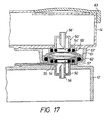
- a rinsing and disinfection cycle is effected in the dialysis machine disinfection liquid being passed from one yaw to the other without passing through a cartridge mounted between them.
- the upper yaw 14 is moved to the lower position in which it is engaged with the lower yaw 12 in the manner described above.
- Operation member 63 is swung upwards, FIG. 10, so that arm 65 disengages the upper notch 66 in guide 13, the yaw is pushed downwards along the guide under compression of hose 68 to the position according to FIG.
- lid 57 on the lower yaw 12 is received by the central opening in lid 57' on the upper yaw 14, FIG. 17, lid 57 on the lower yaw 12 being dimensioned in such a way that the O-ring 62 on the upper yaw 14 seals against the outside of lid 57 as shown in FIG. 17.
- O-rings 54 and 54' have no sealing function, however, with the yaws in this position.
- the O-rings can all easily be exhanged when necessary by lids 57 and 57', respectively, thanks to the bayonet coupling easily being removed from the associated yaw as is necessary in order to get access to the O-rings for exchange. Also bushings 50 and 50' with tube 56 and 56', respectively, for the same reason can be easily exchanged if this would be necessary due to the fact that the pointed end of the tube has become blunt after use for some time. The holder for the cartridge is thus well suited for maintenance and repair works.
- valve in the screw cap can be constructed in another manner.
- sealing rings are kept in position by means of a lid which is removably mounted to the yaw by means of a bayonet coupling but a quick coupling of another type can be provided for mounting the lid which can also be constructed to be screwed onto a hollow stud on the yaw.
- the device for locking the movable yaw in different positions on the guide can also be constructed in another manner than that shown herein.
- the movable yaw can be constructed to be clamped in different positions on guide 13 and it can also be displaceable by means of a screw/nut device or a rack/gear device. Both yaws can also be guided for parallel movement towards and away from each other by means of a link system.
- Each protrusion 65A and 65C, respectively, can be replaced by a spring biassed ball mounted in a seat said ball being pressed back against the spring bias by arm 65 to snap into depression 65B.
- O-rings are suitable sealing rings but sealing rings of another type can no doubt be used in the device described.
- the device of the invention can also be used for mounting cartridges of another embodiment than that shown herein provided, however, with hollow studs for sealed connection with the yaws.
Landscapes
- Health & Medical Sciences (AREA)
- Heart & Thoracic Surgery (AREA)
- Urology & Nephrology (AREA)
- Anesthesiology (AREA)
- Vascular Medicine (AREA)
- Engineering & Computer Science (AREA)
- Emergency Medicine (AREA)
- Biomedical Technology (AREA)
- Hematology (AREA)
- Life Sciences & Earth Sciences (AREA)
- Animal Behavior & Ethology (AREA)
- General Health & Medical Sciences (AREA)
- Public Health (AREA)
- Veterinary Medicine (AREA)
- External Artificial Organs (AREA)
Applications Claiming Priority (3)
| Application Number | Priority Date | Filing Date | Title |
|---|---|---|---|
| SE9502397A SE504633C2 (sv) | 1995-07-03 | 1995-07-03 | Anordning vid dialysmaskin |
| SE9502397 | 1995-07-03 | ||
| PCT/SE1996/000897 WO1997002056A1 (en) | 1995-07-03 | 1996-07-03 | A device in a dialysis machine |
Publications (2)
| Publication Number | Publication Date |
|---|---|
| EP0841959A1 EP0841959A1 (en) | 1998-05-20 |
| EP0841959B1 true EP0841959B1 (en) | 2002-10-02 |
Family
ID=20398819
Family Applications (1)
| Application Number | Title | Priority Date | Filing Date |
|---|---|---|---|
| EP96922362A Expired - Lifetime EP0841959B1 (en) | 1995-07-03 | 1996-07-03 | Dialysis machine |
Country Status (12)
| Country | Link |
|---|---|
| US (1) | US6036858A (enExample) |
| EP (1) | EP0841959B1 (enExample) |
| JP (2) | JP3848371B2 (enExample) |
| AT (1) | ATE225194T1 (enExample) |
| AU (1) | AU6325996A (enExample) |
| DE (1) | DE69624118T2 (enExample) |
| DK (1) | DK0841959T3 (enExample) |
| ES (1) | ES2183963T3 (enExample) |
| PT (1) | PT841959E (enExample) |
| RU (1) | RU2159634C2 (enExample) |
| SE (1) | SE504633C2 (enExample) |
| WO (1) | WO1997002056A1 (enExample) |
Families Citing this family (81)
| Publication number | Priority date | Publication date | Assignee | Title |
|---|---|---|---|---|
| GR970100152A (el) * | 1997-04-18 | 1998-12-31 | Doctum ������������ �. �������� ��� ��� �� | Νεα συσκευη - φυσιγγα διττανθρακικου νατριου με φιλτρο σε καθε ακρο της για αιμοκαθαρση με διττανθρακικα |
| SE520638C2 (sv) | 1998-01-21 | 2003-08-05 | Gambro Lundia Ab | Säkerhetsanordning vid dialysmaskin |
| DE19852982C1 (de) | 1998-11-17 | 2000-03-16 | Braun Melsungen Ag | Kartuschenhalter für eine Dialysemaschine |
| IT1307734B1 (it) * | 1999-01-29 | 2001-11-19 | Bieffe Medital Spa | Cartuccia per dialisi contenente bicarbonato di sodio. |
| US6355161B1 (en) | 1999-10-12 | 2002-03-12 | Aksys, Ltd. | Bottles for dialysis machines and method for automatically identifying such bottles |
| DE10152105A1 (de) * | 2001-10-23 | 2003-05-08 | Fresenius Medical Care De Gmbh | Behältnis zur Verwendung in der Dialyse |
| AU2003233023B2 (en) | 2002-06-24 | 2008-05-15 | Gambro Lundia Ab | Gas separation devices |
| USD483872S1 (en) | 2002-09-27 | 2003-12-16 | Baxter International Inc. | Display portion for a medical machine |
| USD484982S1 (en) | 2002-09-27 | 2004-01-06 | Baxter International Inc. | Chassis for a medical machine |
| US7591945B2 (en) | 2003-02-07 | 2009-09-22 | Gambro Lundia Ab | Support device for containers in extracorporeal blood treatment machines |
| US7247146B2 (en) | 2003-02-07 | 2007-07-24 | Gambro Lundia Ab | Support element for an integrated blood treatment module, integrated blood treatment module and extracorporeal blood treatment apparatus equipped with said integrated module |
| US7223338B2 (en) | 2003-02-07 | 2007-05-29 | Gambro Lundia Ab | Support element for an integrated module for blood treatment, an integrated module for blood treatment, and a manufacturing process for an integrated module for blood treatment |
| US7223336B2 (en) | 2003-02-07 | 2007-05-29 | Gambro Lundia Ab | Integrated blood treatment module and extracorporeal blood treatment apparatus |
| US7314554B2 (en) | 2003-02-07 | 2008-01-01 | Gambro Lundia Ab | Extracorporeal blood treatment machine |
| US7850659B1 (en) * | 2003-08-18 | 2010-12-14 | Medrad, Inc. | Fluid container holding device, fluid delivery system and method of use therefor |
| US8029454B2 (en) | 2003-11-05 | 2011-10-04 | Baxter International Inc. | High convection home hemodialysis/hemofiltration and sorbent system |
| US8038639B2 (en) | 2004-11-04 | 2011-10-18 | Baxter International Inc. | Medical fluid system with flexible sheeting disposable unit |
| JP4655296B2 (ja) * | 2005-05-23 | 2011-03-23 | 日機装株式会社 | 容器ホルダ |
| USD550373S1 (en) * | 2005-10-10 | 2007-09-04 | Gambro Lundia Ab | Blood or plasma treatment apparatus |
| US7871391B2 (en) | 2005-10-21 | 2011-01-18 | Fresenius Medical Care Holdings, Inc. | Extracorporeal fluid circuit |
| US8631683B2 (en) | 2007-02-06 | 2014-01-21 | Fresenius Medical Care Holdings, Inc. | Dialysis systems including non-invasive multi-function sensor systems |
| DE102007009269B4 (de) * | 2007-02-26 | 2010-11-11 | Fresenius Medical Care Deutschland Gmbh | Vorrichtung und Verfahren zum Befüllen und/oder Entleeren eines Dialysegerätes |
| CA2698409C (en) * | 2007-09-19 | 2016-01-12 | Fresenius Medical Care Holdings, Inc. | Dialysis systems and related components |
| AU2008302306B2 (en) | 2007-09-19 | 2013-10-03 | Fresenius Medical Care Holdings, Inc. | Safety vent structure for extracorporeal circuit |
| ATE536195T1 (de) | 2007-10-04 | 2011-12-15 | Gambro Lundia Ab | Infusionsgerät |
| US8114276B2 (en) | 2007-10-24 | 2012-02-14 | Baxter International Inc. | Personal hemodialysis system |
| CA2704011C (en) | 2007-11-16 | 2016-07-05 | Fresenius Medical Care Holdings, Inc. | Dialysis systems and methods |
| US8889004B2 (en) | 2007-11-16 | 2014-11-18 | Fresenius Medical Care Holdings, Inc. | Dialysis systems and methods |
| USD611152S1 (en) | 2009-05-18 | 2010-03-02 | Fresenius Medical Care Holdings, Inc. | Dialysis system sorbent cartridge mount |
| AU2010279725B2 (en) | 2009-08-04 | 2014-10-02 | Fresenius Medical Care Holdings, Inc. | Dialysis systems, components, and methods |
| US8500994B2 (en) | 2010-01-07 | 2013-08-06 | Fresenius Medical Care Holdings, Inc. | Dialysis systems and methods |
| US9220832B2 (en) | 2010-01-07 | 2015-12-29 | Fresenius Medical Care Holdings, Inc. | Dialysis systems and methods |
| US8449686B2 (en) | 2010-04-26 | 2013-05-28 | Fresenius Medical Care Holdings, Inc. | Methods for cleaning a drain line of a dialysis machine |
| WO2012041790A1 (en) * | 2010-09-28 | 2012-04-05 | Akzo Nobel Chemicals International B.V. | Process and container for dissolving salt |
| US8784668B2 (en) | 2010-10-12 | 2014-07-22 | Fresenius Medical Care Holdings, Inc. | Systems and methods for compensation of compliant behavior in regenerative dialysis systems |
| CN102125707B (zh) * | 2011-01-27 | 2012-07-25 | 重庆山外山科技有限公司 | 一种血液净化用干粉筒装置 |
| DE102011009908A1 (de) | 2011-01-31 | 2012-08-02 | Fresenius Medical Care Deutschland Gmbh | Klemmhalterung für eine Spritze einer Dosiervorrichtung, Dosiervorrichtung und Blutbehandlungsvorrichtung |
| US9333286B2 (en) | 2011-05-12 | 2016-05-10 | Fresenius Medical Care Holdings, Inc. | Medical tubing installation detection |
| US8836519B2 (en) | 2011-05-12 | 2014-09-16 | Fresenius Medical Care Holdings, Inc. | Determining the absence or presence of fluid in a dialysis system |
| WO2013028809A2 (en) * | 2011-08-22 | 2013-02-28 | Medtronic, Inc. | Dual flow sorbent cartridge |
| US8906240B2 (en) | 2011-08-29 | 2014-12-09 | Fresenius Medical Care Holdings, Inc. | Early detection of low bicarbonate level |
| USD711001S1 (en) * | 2011-08-29 | 2014-08-12 | General Electric Company | Anesthesiology machine |
| US8992777B2 (en) | 2011-11-18 | 2015-03-31 | Fresenius Medical Care Holdings, Inc. | Systems and methods for providing notifications in dialysis systems |
| AU343633S (en) * | 2012-01-12 | 2012-08-01 | Draegerwerk Ag & Co Kgaa | Anaesthetic apparatus |
| US9165112B2 (en) | 2012-02-03 | 2015-10-20 | Fresenius Medical Care Holdings, Inc. | Systems and methods for displaying objects at a medical treatment apparatus display screen |
| DE102012002497A1 (de) | 2012-02-10 | 2013-08-14 | Fresenius Medical Care Deutschland Gmbh | Verbinder mit einem Behälter zur Herstellung einer individuell angepassten Lösung für die Dialyse |
| DE102012111428A1 (de) * | 2012-11-26 | 2014-05-28 | B. Braun Avitum Ag | Kartuschenhalterung für eine Dialysemaschine |
| DE102012111429A1 (de) * | 2012-11-26 | 2014-06-18 | B. Braun Avitum Ag | Kartuschenhalterung einer Dialysemaschine mit integrierter Positionierhilfe |
| US9713666B2 (en) | 2013-01-09 | 2017-07-25 | Medtronic, Inc. | Recirculating dialysate fluid circuit for blood measurement |
| US11154648B2 (en) | 2013-01-09 | 2021-10-26 | Medtronic, Inc. | Fluid circuits for sorbent cartridge with sensors |
| US9144640B2 (en) | 2013-02-02 | 2015-09-29 | Medtronic, Inc. | Sorbent cartridge configurations for improved dialysate regeneration |
| US9433721B2 (en) | 2013-06-25 | 2016-09-06 | Fresenius Medical Care Holdings, Inc. | Vial spiking assemblies and related methods |
| US10004839B2 (en) | 2013-11-26 | 2018-06-26 | Medtronic, Inc. | Multi-use sorbent cartridge |
| US9884145B2 (en) | 2013-11-26 | 2018-02-06 | Medtronic, Inc. | Parallel modules for in-line recharging of sorbents using alternate duty cycles |
| US9895477B2 (en) | 2013-11-26 | 2018-02-20 | Medtronic, Inc. | Detachable module for recharging sorbent materials with optional bypass |
| US10537875B2 (en) | 2013-11-26 | 2020-01-21 | Medtronic, Inc. | Precision recharging of sorbent materials using patient and session data |
| US10052612B2 (en) | 2013-11-26 | 2018-08-21 | Medtronic, Inc. | Zirconium phosphate recharging method and apparatus |
| US9943780B2 (en) | 2013-11-26 | 2018-04-17 | Medtronic, Inc. | Module for in-line recharging of sorbent materials with optional bypass |
| US10286380B2 (en) | 2014-06-24 | 2019-05-14 | Medtronic, Inc. | Sorbent pouch |
| WO2015199766A1 (en) | 2014-06-24 | 2015-12-30 | Medtronic, Inc. | Modular dialysate regeneration assembly |
| EP3160529B1 (en) | 2014-06-24 | 2019-11-13 | Medtronic Inc. | Replenishing urease in dialysis systems using urease pouches |
| EP3160532B1 (en) | 2014-06-24 | 2019-09-18 | Medtronic Inc. | A urease introduction system for replenishing urease in a sorbent cartridge |
| EP3160531B1 (en) | 2014-06-24 | 2019-08-14 | Medtronic Inc. | Replenisihing urease in dialysis systems using a urease introducer |
| US10357757B2 (en) | 2014-06-24 | 2019-07-23 | Medtronic, Inc. | Stacked sorbent assembly |
| EP2979712B1 (en) | 2014-07-31 | 2017-03-22 | Gambro Lundia AB | Medical apparatus for the preparation of medical fluid |
| US9974942B2 (en) | 2015-06-19 | 2018-05-22 | Fresenius Medical Care Holdings, Inc. | Non-vented vial drug delivery |
| JP2018201532A (ja) * | 2015-09-29 | 2018-12-27 | 日機装株式会社 | 透析液供給装置 |
| JP7025408B2 (ja) | 2016-08-19 | 2022-02-24 | アウトセット・メディカル・インコーポレイテッド | 腹膜透析システム及び方法 |
| US10981148B2 (en) | 2016-11-29 | 2021-04-20 | Medtronic, Inc. | Zirconium oxide module conditioning |
| US11167070B2 (en) | 2017-01-30 | 2021-11-09 | Medtronic, Inc. | Ganged modular recharging system |
| US10960381B2 (en) | 2017-06-15 | 2021-03-30 | Medtronic, Inc. | Zirconium phosphate disinfection recharging and conditioning |
| US12285552B2 (en) | 2018-08-14 | 2025-04-29 | Mozarc Medical Us Llc | Precision dialysis therapy based on sorbent effluent analysis |
| US11213616B2 (en) | 2018-08-24 | 2022-01-04 | Medtronic, Inc. | Recharge solution for zirconium phosphate |
| AU2020266584B2 (en) * | 2019-04-30 | 2025-10-23 | Outset Medical, Inc. | Dialysis system and methods |
| CN110124141B (zh) * | 2019-06-11 | 2021-09-21 | 聊城市人民医院 | 血液灌流装置 |
| CN112472893A (zh) * | 2019-09-12 | 2021-03-12 | 费森尤斯医疗护理德国有限责任公司 | 用于将浓缩物容器与血液处理装置连接的系统和方法 |
| US12390566B2 (en) * | 2019-09-12 | 2025-08-19 | Fresenius Medical Care Deutschland Gmbh | System and method for connecting a concentrate container with a blood treatment device |
| EP3791903A1 (en) * | 2019-09-12 | 2021-03-17 | Fresenius Medical Care Deutschland GmbH | System and method for connecting a concentrate container with a blood treatment device |
| US12377198B2 (en) | 2019-09-12 | 2025-08-05 | Fresenius Medical Care Deutschland Gmbh | System and method for connecting a concentrate container with a blood treatment device |
| TWI858127B (zh) * | 2019-09-12 | 2024-10-11 | 德商費森尤斯醫療護理德國有限責任公司 | 用於連接濃縮液容器與血液治療裝置之系統及方法 |
| US12397093B2 (en) | 2021-05-18 | 2025-08-26 | Mozarc Medical Us Llc | Sorbent cartridge designs |
Family Cites Families (10)
| Publication number | Priority date | Publication date | Assignee | Title |
|---|---|---|---|---|
| US3872868A (en) * | 1973-09-27 | 1975-03-25 | Joel B Kline | Universal hospital container |
| US4005844A (en) * | 1975-08-25 | 1977-02-01 | Stryker Corporation | Solution bottle holder |
| US4387873A (en) * | 1981-03-16 | 1983-06-14 | Baxter Travenol Laboratories, Inc. | Device for suspension of a solution container |
| US4676467A (en) * | 1985-10-31 | 1987-06-30 | Cobe Laboratories, Inc. | Apparatus for supporting a fluid flow cassette |
| US4784495A (en) * | 1987-02-06 | 1988-11-15 | Gambro Ab | System for preparing a fluid intended for a medical procedure by mixing at least one concentrate in powder form with water |
| SE505967C2 (sv) * | 1990-10-15 | 1997-10-27 | Gambro Ab | Förfarande respektive anläggning för beredning av en medicinsk lösning, t ex en dialyslösning |
| DE4138140C2 (de) * | 1991-11-20 | 1993-12-23 | Fresenius Ag | Vorrichtung zur Desinfektion von Hämodialysegeräten mit einem pulverförmigen Konzentrat |
| US5275724A (en) * | 1991-12-10 | 1994-01-04 | Millipore Corporation | Connector apparatus and system |
| SE504572C2 (sv) * | 1995-06-06 | 1997-03-10 | Gambro Ab | Kombinerad hållare och konnektor för dialysator |
| US5641144A (en) * | 1995-06-07 | 1997-06-24 | Cobe Laboratories, Inc. | Dialyzer holder |
-
1995
- 1995-07-03 SE SE9502397A patent/SE504633C2/sv not_active IP Right Cessation
-
1996
- 1996-07-03 DE DE69624118T patent/DE69624118T2/de not_active Expired - Lifetime
- 1996-07-03 ES ES96922362T patent/ES2183963T3/es not_active Expired - Lifetime
- 1996-07-03 RU RU98101630/14A patent/RU2159634C2/ru not_active IP Right Cessation
- 1996-07-03 AT AT96922362T patent/ATE225194T1/de not_active IP Right Cessation
- 1996-07-03 DK DK96922362T patent/DK0841959T3/da active
- 1996-07-03 PT PT96922362T patent/PT841959E/pt unknown
- 1996-07-03 WO PCT/SE1996/000897 patent/WO1997002056A1/en not_active Ceased
- 1996-07-03 JP JP50508297A patent/JP3848371B2/ja not_active Expired - Fee Related
- 1996-07-03 EP EP96922362A patent/EP0841959B1/en not_active Expired - Lifetime
- 1996-07-03 AU AU63259/96A patent/AU6325996A/en not_active Abandoned
- 1996-07-03 US US08/983,592 patent/US6036858A/en not_active Expired - Lifetime
-
2006
- 2006-02-08 JP JP2006031614A patent/JP2006122719A/ja not_active Withdrawn
Also Published As
| Publication number | Publication date |
|---|---|
| DE69624118D1 (de) | 2002-11-07 |
| AU6325996A (en) | 1997-02-05 |
| JPH11508469A (ja) | 1999-07-27 |
| US6036858A (en) | 2000-03-14 |
| JP3848371B2 (ja) | 2006-11-22 |
| WO1997002056A1 (en) | 1997-01-23 |
| SE504633C2 (sv) | 1997-03-24 |
| ES2183963T3 (es) | 2003-04-01 |
| JP2006122719A (ja) | 2006-05-18 |
| DE69624118T2 (de) | 2003-06-05 |
| PT841959E (pt) | 2002-12-31 |
| SE9502397L (sv) | 1997-01-04 |
| EP0841959A1 (en) | 1998-05-20 |
| ATE225194T1 (de) | 2002-10-15 |
| DK0841959T3 (da) | 2002-10-28 |
| RU2159634C2 (ru) | 2000-11-27 |
| SE9502397D0 (sv) | 1995-07-03 |
Similar Documents
| Publication | Publication Date | Title |
|---|---|---|
| EP0841959B1 (en) | Dialysis machine | |
| US6000567A (en) | Device in a powder cartridge for a dialysis machine | |
| US5445623A (en) | Drip chamber with luer fitting | |
| US4798605A (en) | Device for connecting and draining a pouch | |
| EP0458041B1 (en) | System for controlling a medical treatment, for example dialysis | |
| CA1270777A (en) | Three-way connector for liquid exchange | |
| US6355161B1 (en) | Bottles for dialysis machines and method for automatically identifying such bottles | |
| US20090143723A1 (en) | Flow control device for peritoneal dialysis | |
| EP0717316B1 (en) | Apparatus for emptying and rinsing out photographic chemical containers into a mixing tank | |
| EP0256640B1 (en) | Connecting device for peritoneal dialysis | |
| DE19605260A1 (de) | Modulares Heimdialysesystem | |
| KR101924126B1 (ko) | 수액 세트 | |
| GB2118440A (en) | A self-sealing connector | |
| JP7223359B2 (ja) | ポート装置、ポート装置を含む精製水生成装置及び精製水生成装置のポート洗浄を行うための方法 | |
| CA2223473C (en) | Device in a dialysis machine | |
| WO2021180804A1 (en) | System and method for opening a concentrate container and connecting the concentrate container to a blood treatment device | |
| GB2578182A (en) | Fluid conduit module for attachment to an endoscope | |
| SE432998B (sv) | System vid med vetskeformig gas under tryck drivna apparater | |
| CN116077820A (zh) | 一种连续非卧床腹膜透析装置流量控制阀和使用方法 | |
| CN222032315U (zh) | 一种测压瓶 | |
| KR101853250B1 (ko) | 뼈수집장치 | |
| CN118224080A (zh) | 一种灌注泵组件及其拆装方法 | |
| FI112326B (fi) | Pussi konsentraatin vastaanottamiseksi | |
| EP4028074A1 (en) | System and method for connecting a concentrate container with a blood treatment device without leakages | |
| HK1167591A1 (en) | Access port |
Legal Events
| Date | Code | Title | Description |
|---|---|---|---|
| PUAI | Public reference made under article 153(3) epc to a published international application that has entered the european phase |
Free format text: ORIGINAL CODE: 0009012 |
|
| AK | Designated contracting states |
Kind code of ref document: A1 Designated state(s): AT BE CH DE DK ES FI FR GB GR IE IT LI LU MC NL PT SE |
|
| 17P | Request for examination filed |
Effective date: 19980128 |
|
| GRAG | Despatch of communication of intention to grant |
Free format text: ORIGINAL CODE: EPIDOS AGRA |
|
| RTI1 | Title (correction) |
Free format text: DIALYSIS MACHINE |
|
| 17Q | First examination report despatched |
Effective date: 20011022 |
|
| GRAG | Despatch of communication of intention to grant |
Free format text: ORIGINAL CODE: EPIDOS AGRA |
|
| GRAH | Despatch of communication of intention to grant a patent |
Free format text: ORIGINAL CODE: EPIDOS IGRA |
|
| GRAH | Despatch of communication of intention to grant a patent |
Free format text: ORIGINAL CODE: EPIDOS IGRA |
|
| GRAA | (expected) grant |
Free format text: ORIGINAL CODE: 0009210 |
|
| AK | Designated contracting states |
Kind code of ref document: B1 Designated state(s): AT BE CH DE DK ES FI FR GB GR IE IT LI LU MC NL PT SE |
|
| REF | Corresponds to: |
Ref document number: 225194 Country of ref document: AT Date of ref document: 20021015 Kind code of ref document: T |
|
| REG | Reference to a national code |
Ref country code: GB Ref legal event code: FG4D |
|
| REG | Reference to a national code |
Ref country code: CH Ref legal event code: EP |
|
| REG | Reference to a national code |
Ref country code: DK Ref legal event code: T3 |
|
| REG | Reference to a national code |
Ref country code: IE Ref legal event code: FG4D |
|
| REG | Reference to a national code |
Ref country code: CH Ref legal event code: NV Representative=s name: KIRKER & CIE SA |
|
| REF | Corresponds to: |
Ref document number: 69624118 Country of ref document: DE Date of ref document: 20021107 |
|
| REG | Reference to a national code |
Ref country code: PT Ref legal event code: SC4A Free format text: AVAILABILITY OF NATIONAL TRANSLATION Effective date: 20021028 |
|
| REG | Reference to a national code |
Ref country code: GR Ref legal event code: EP Ref document number: 20020404230 Country of ref document: GR |
|
| ET | Fr: translation filed | ||
| REG | Reference to a national code |
Ref country code: ES Ref legal event code: FG2A Ref document number: 2183963 Country of ref document: ES Kind code of ref document: T3 |
|
| PG25 | Lapsed in a contracting state [announced via postgrant information from national office to epo] |
Ref country code: LU Free format text: LAPSE BECAUSE OF NON-PAYMENT OF DUE FEES Effective date: 20030703 Ref country code: IE Free format text: LAPSE BECAUSE OF NON-PAYMENT OF DUE FEES Effective date: 20030703 Ref country code: FI Free format text: LAPSE BECAUSE OF NON-PAYMENT OF DUE FEES Effective date: 20030703 |
|
| PG25 | Lapsed in a contracting state [announced via postgrant information from national office to epo] |
Ref country code: MC Free format text: LAPSE BECAUSE OF NON-PAYMENT OF DUE FEES Effective date: 20030731 |
|
| PLBE | No opposition filed within time limit |
Free format text: ORIGINAL CODE: 0009261 |
|
| STAA | Information on the status of an ep patent application or granted ep patent |
Free format text: STATUS: NO OPPOSITION FILED WITHIN TIME LIMIT |
|
| 26N | No opposition filed |
Effective date: 20030703 |
|
| PG25 | Lapsed in a contracting state [announced via postgrant information from national office to epo] |
Ref country code: PT Free format text: LAPSE BECAUSE OF NON-PAYMENT OF DUE FEES Effective date: 20040131 |
|
| PG25 | Lapsed in a contracting state [announced via postgrant information from national office to epo] |
Ref country code: GR Free format text: LAPSE BECAUSE OF NON-PAYMENT OF DUE FEES Effective date: 20040205 |
|
| REG | Reference to a national code |
Ref country code: PT Ref legal event code: MM4A Free format text: LAPSE DUE TO NON-PAYMENT OF FEES Effective date: 20040131 |
|
| REG | Reference to a national code |
Ref country code: IE Ref legal event code: MM4A |
|
| PGFP | Annual fee paid to national office [announced via postgrant information from national office to epo] |
Ref country code: DK Payment date: 20090728 Year of fee payment: 14 |
|
| PGFP | Annual fee paid to national office [announced via postgrant information from national office to epo] |
Ref country code: NL Payment date: 20090724 Year of fee payment: 14 |
|
| PGFP | Annual fee paid to national office [announced via postgrant information from national office to epo] |
Ref country code: IT Payment date: 20100729 Year of fee payment: 15 Ref country code: AT Payment date: 20100621 Year of fee payment: 15 |
|
| REG | Reference to a national code |
Ref country code: NL Ref legal event code: V1 Effective date: 20110201 |
|
| PGFP | Annual fee paid to national office [announced via postgrant information from national office to epo] |
Ref country code: BE Payment date: 20100728 Year of fee payment: 15 |
|
| PG25 | Lapsed in a contracting state [announced via postgrant information from national office to epo] |
Ref country code: NL Free format text: LAPSE BECAUSE OF NON-PAYMENT OF DUE FEES Effective date: 20110201 |
|
| REG | Reference to a national code |
Ref country code: DK Ref legal event code: EBP |
|
| PGFP | Annual fee paid to national office [announced via postgrant information from national office to epo] |
Ref country code: CH Payment date: 20110725 Year of fee payment: 16 |
|
| BERE | Be: lapsed |
Owner name: *ALTHIN MEDICAL A.B. Effective date: 20110731 |
|
| REG | Reference to a national code |
Ref country code: AT Ref legal event code: MM01 Ref document number: 225194 Country of ref document: AT Kind code of ref document: T Effective date: 20110703 |
|
| PG25 | Lapsed in a contracting state [announced via postgrant information from national office to epo] |
Ref country code: BE Free format text: LAPSE BECAUSE OF NON-PAYMENT OF DUE FEES Effective date: 20110731 |
|
| PG25 | Lapsed in a contracting state [announced via postgrant information from national office to epo] |
Ref country code: IT Free format text: LAPSE BECAUSE OF NON-PAYMENT OF DUE FEES Effective date: 20110703 |
|
| PG25 | Lapsed in a contracting state [announced via postgrant information from national office to epo] |
Ref country code: DK Free format text: LAPSE BECAUSE OF NON-PAYMENT OF DUE FEES Effective date: 20100802 |
|
| PG25 | Lapsed in a contracting state [announced via postgrant information from national office to epo] |
Ref country code: AT Free format text: LAPSE BECAUSE OF NON-PAYMENT OF DUE FEES Effective date: 20110703 |
|
| REG | Reference to a national code |
Ref country code: CH Ref legal event code: PL |
|
| PG25 | Lapsed in a contracting state [announced via postgrant information from national office to epo] |
Ref country code: LI Free format text: LAPSE BECAUSE OF NON-PAYMENT OF DUE FEES Effective date: 20120731 Ref country code: CH Free format text: LAPSE BECAUSE OF NON-PAYMENT OF DUE FEES Effective date: 20120731 |
|
| PGFP | Annual fee paid to national office [announced via postgrant information from national office to epo] |
Ref country code: SE Payment date: 20130729 Year of fee payment: 18 Ref country code: ES Payment date: 20130726 Year of fee payment: 18 |
|
| PGFP | Annual fee paid to national office [announced via postgrant information from national office to epo] |
Ref country code: GB Payment date: 20130729 Year of fee payment: 18 Ref country code: FR Payment date: 20130717 Year of fee payment: 18 |
|
| PGFP | Annual fee paid to national office [announced via postgrant information from national office to epo] |
Ref country code: DE Payment date: 20140729 Year of fee payment: 19 |
|
| REG | Reference to a national code |
Ref country code: SE Ref legal event code: EUG |
|
| GBPC | Gb: european patent ceased through non-payment of renewal fee |
Effective date: 20140703 |
|
| REG | Reference to a national code |
Ref country code: FR Ref legal event code: ST Effective date: 20150331 |
|
| PG25 | Lapsed in a contracting state [announced via postgrant information from national office to epo] |
Ref country code: SE Free format text: LAPSE BECAUSE OF NON-PAYMENT OF DUE FEES Effective date: 20140704 Ref country code: GB Free format text: LAPSE BECAUSE OF NON-PAYMENT OF DUE FEES Effective date: 20140703 Ref country code: FR Free format text: LAPSE BECAUSE OF NON-PAYMENT OF DUE FEES Effective date: 20140731 |
|
| REG | Reference to a national code |
Ref country code: ES Ref legal event code: FD2A Effective date: 20150828 |
|
| PG25 | Lapsed in a contracting state [announced via postgrant information from national office to epo] |
Ref country code: ES Free format text: LAPSE BECAUSE OF NON-PAYMENT OF DUE FEES Effective date: 20140704 |
|
| REG | Reference to a national code |
Ref country code: DE Ref legal event code: R119 Ref document number: 69624118 Country of ref document: DE |
|
| PG25 | Lapsed in a contracting state [announced via postgrant information from national office to epo] |
Ref country code: DE Free format text: LAPSE BECAUSE OF NON-PAYMENT OF DUE FEES Effective date: 20160202 |