EP0841539B1 - Dispositif pour la mesure de position et procédé de montage d'un dispositif de lecture dans un tel dispositif pour la mesure de position - Google Patents
Dispositif pour la mesure de position et procédé de montage d'un dispositif de lecture dans un tel dispositif pour la mesure de position Download PDFInfo
- Publication number
- EP0841539B1 EP0841539B1 EP97119215A EP97119215A EP0841539B1 EP 0841539 B1 EP0841539 B1 EP 0841539B1 EP 97119215 A EP97119215 A EP 97119215A EP 97119215 A EP97119215 A EP 97119215A EP 0841539 B1 EP0841539 B1 EP 0841539B1
- Authority
- EP
- European Patent Office
- Prior art keywords
- measuring device
- mounting element
- sensing
- mounting
- positioning means
- Prior art date
- Legal status (The legal status is an assumption and is not a legal conclusion. Google has not performed a legal analysis and makes no representation as to the accuracy of the status listed.)
- Expired - Lifetime
Links
- 238000000034 method Methods 0.000 title claims description 6
- 230000002093 peripheral effect Effects 0.000 claims description 2
- 238000005259 measurement Methods 0.000 abstract description 2
- 239000010408 film Substances 0.000 description 6
- 238000003892 spreading Methods 0.000 description 3
- 230000001939 inductive effect Effects 0.000 description 2
- 238000004026 adhesive bonding Methods 0.000 description 1
- 230000001419 dependent effect Effects 0.000 description 1
- 238000006073 displacement reaction Methods 0.000 description 1
- 238000005553 drilling Methods 0.000 description 1
- 230000000694 effects Effects 0.000 description 1
- 238000005516 engineering process Methods 0.000 description 1
- 230000005284 excitation Effects 0.000 description 1
- 238000009434 installation Methods 0.000 description 1
- 239000000463 material Substances 0.000 description 1
- 239000012811 non-conductive material Substances 0.000 description 1
- 238000003825 pressing Methods 0.000 description 1
- 239000004065 semiconductor Substances 0.000 description 1
- 125000006850 spacer group Chemical group 0.000 description 1
- 238000003860 storage Methods 0.000 description 1
- 239000000758 substrate Substances 0.000 description 1
- 239000010409 thin film Substances 0.000 description 1
- 238000004804 winding Methods 0.000 description 1
Images

Classifications
-
- G—PHYSICS
- G01—MEASURING; TESTING
- G01D—MEASURING NOT SPECIALLY ADAPTED FOR A SPECIFIC VARIABLE; ARRANGEMENTS FOR MEASURING TWO OR MORE VARIABLES NOT COVERED IN A SINGLE OTHER SUBCLASS; TARIFF METERING APPARATUS; MEASURING OR TESTING NOT OTHERWISE PROVIDED FOR
- G01D5/00—Mechanical means for transferring the output of a sensing member; Means for converting the output of a sensing member to another variable where the form or nature of the sensing member does not constrain the means for converting; Transducers not specially adapted for a specific variable
- G01D5/26—Mechanical means for transferring the output of a sensing member; Means for converting the output of a sensing member to another variable where the form or nature of the sensing member does not constrain the means for converting; Transducers not specially adapted for a specific variable characterised by optical transfer means, i.e. using infrared, visible, or ultraviolet light
- G01D5/32—Mechanical means for transferring the output of a sensing member; Means for converting the output of a sensing member to another variable where the form or nature of the sensing member does not constrain the means for converting; Transducers not specially adapted for a specific variable characterised by optical transfer means, i.e. using infrared, visible, or ultraviolet light with attenuation or whole or partial obturation of beams of light
- G01D5/34—Mechanical means for transferring the output of a sensing member; Means for converting the output of a sensing member to another variable where the form or nature of the sensing member does not constrain the means for converting; Transducers not specially adapted for a specific variable characterised by optical transfer means, i.e. using infrared, visible, or ultraviolet light with attenuation or whole or partial obturation of beams of light the beams of light being detected by photocells
- G01D5/347—Mechanical means for transferring the output of a sensing member; Means for converting the output of a sensing member to another variable where the form or nature of the sensing member does not constrain the means for converting; Transducers not specially adapted for a specific variable characterised by optical transfer means, i.e. using infrared, visible, or ultraviolet light with attenuation or whole or partial obturation of beams of light the beams of light being detected by photocells using displacement encoding scales
- G01D5/34707—Scales; Discs, e.g. fixation, fabrication, compensation
Definitions
- the invention relates to a position measuring device according to the preamble of claim 1 and a method for mounting a scanning unit Position measuring device according to the preamble of claim 11.
- a material measure is made up of a scanning element scanned.
- position-dependent electrical scanning signals obtained by subsequent electronics, for example a meter or a numerical control.
- the quality of the scanning signals depends on the scanning distance, which is why is required, the scanning element at a precisely defined distance relative to be mounted to the measuring standard.
- a position measuring device is described in EP 0 177 711 B1, at which a scanning element in the form of a scanning graduation in a guide for adjustment of the scanning distance is slidably mounted and in any position can be locked.
- the required scanning distance is determined by a spacing film specified during assembly between the measuring standard and the scanning graduation is inserted.
- the scanning division is shifted up to Clamp the film, then the scanning graduation is locked and the film away.
- EP 0 280 390 A1 and DE 37 40 744 A1 there is a position measuring device known in the form of an encoder, which does not have its own storage having. Such encoders are referred to as built-in encoders.
- the Relative position of the scanning unit to the indexing disc is the first with built-in encoders fixed in the attached state to the objects to be measured.
- a fixing element or connecting part in the encoder integrated which is in contact with the hub of the indexing disc and determines the relative position of the scanning unit to the indexing disc during the attachment. After the partial disk has been mounted on the object to be measured and the scanning unit to the other object to be measured becomes the fixing element or the connecting part removed.
- the invention has for its object to a position measuring device create that is simple and with the required scanning distance is easily adjustable.
- This task is performed by the position measuring device with the features of claim 1 solved.
- the advantages of the invention are in particular that the scanning distance is already determined by the components of the scanning unit itself and none loss of film is needed.
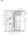
- an angle measuring device is shown, which is on a drive device is attached.
- the drive device is a motor with a mounted shaft 1, the angle of rotation relative to the stator 2 with the angle measuring device should be measured.
- a shaft 1 Measuring standard attached in the form of a graduated disk 3. This attachment can be done by screwing, gluing, pressing or clamping.
- the dividing disc 3 bears a division 3.2 or a coding on a level 3.1, which can be scanned electrically, magnetically, capacitively or inductively.
- the division 3.2 is the position measurement in a conventional manner scanned by a scanning unit 4.
- the scanning unit 4 consists of a Scanning element 5 and a mounting element 6.
- the scanning element 5 is over a guide on the mounting element 6 in the direction of the division 3.2 - that is perpendicular to level 3.1 - slidably mounted.
- the leadership is in the example formed by a threaded bore 8 in the mounting element 6, in the a screw 9 is rotatably mounted. At one end of the screw 9 is fastened the scanning element 5 such that it is relative to the mounting element 6 is displaceable in two defined reference positions. The shift takes place by turning the screw 9, which is why the screw 9 is also used as a positioning element can be designated.
- the first reference position - too Called assembly position - is shown in Figures 1 and 2.
- This State acts a first axially acting stop surface 9.1 of the screw 9 with a first axially acting stop surface 6.1 of the mounting element 6 together.
- a stop surface 9.3 of the screw 9 also acts with a Stop surface 5.3 of the scanning element 5 together.
- the scanning unit 4 with the stator 2 the drive device is torsionally coupled.
- the scanning unit 4 axially to the division level 3.1 in the tube 2.1 until the Scanning element 5 is in contact with the graduated disk 3.
- the scanning unit 4 is attached to the stator 2 by means of the mounting element 6 fixed.
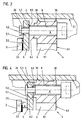
- the screw is now used to set the required scanning distance D. 9 rotated until a second stop surface 6.2 of the mounting element 6 with a second stop surface 9.2 of the screw 9 cooperates.
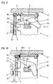
- This the second reference position - also called the operating position - is shown in FIGS. 3 and 4.
- this second stop surface 6.2 acts Mounting element 6 with the interposition of the disc 5 with the second stop surface 9.2 of the screw 9 together.
- the scanning distance is in practice about 0.5 to 1 mm.
- the scanning element 5 with the help of the screw 9 in two Reference positions is movable relative to the mounting member 6, the Reference positions are specified by parts of the scanning unit 4 itself. Due to the distance between the two reference positions, the scanning distance is D certainly.
- the shift from the first to the second reference position takes place perpendicular to the division plane 3.1, in the angle measuring device shown thus in the direction of the axis of rotation R.
- the stop surfaces 6.1, 6.2, 9.1 and 9.2 run perpendicular to the axis of rotation R.
- the angle measuring device on the basis of which the invention is explained by way of example is an inductively operating device such as that in principle in EP 0 182 085 B1 is described.
- the graduated disk 3 consists of electrically non-conductive Material, and at level 3.1 an incremental division is made spaced apart electrically conductive areas 3.2 applied.
- the scanning element 5 is a circuit board, on the surface of which 5.1 excitation Sensor windings are applied in thin-film technology.
- the board 5 is also disc-shaped.
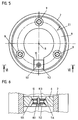
- the relatively large and unstable circuit board 5 defined to be able to move relative to the mounting element 6 three 120 ° offset screws 9 as positioning elements be provided, as can be seen from Figure 5.
- FIGs 2 and 4 is shown schematically how the screw 9 in one Elongated hole 20 of the scanning element 5 (circuit board) is moved.
- the scanning distance there is an axial displacement of the screw 9 in the elongated hole 20.
- Moved when the mounting element 6 is spread the screw 9 radially outwards which is why the longitudinal axis of the elongated hole Starting from the axis R 20 extends radially outward.
- the diameter of the elongated hole 20 corresponds perpendicular to the longitudinal axis exactly the diameter of the engaging screw 9.
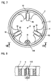
- the mounting element 6 is an annular Part whose outer diameter is slightly smaller than the inner diameter of the stator 2. As shown in Figure 5, is in the Mounting element 6 a radially extending slot 10 is provided. This Slot 10 allows the mounting element 6 to be spread apart and thus an increase in the outer diameter. For radial spreading is a spreading element 11 is provided. According to FIG. 6, it consists of a Screw 11.1, with the two arranged one behind the other in the axial direction Clamping elements 11.2 and 11.3 can be moved in opposite directions. The clamping elements 11.2 and 11.3 act with conical surfaces 11.4 and 11.5 of the mounting element 6 together where they rest.
- the stator 2 is the housing or the flange (Motor end shield) of the electric motor.
- the radial clamping means a clamping or spreading into one Direction that is at least largely perpendicular to the axis of rotation R.
- the radial clamping can be on an inner or outer peripheral surface of the Stator 2 act.
- the clamping element can be used to spread the mounting element 6 can also be a conical screw, the cone of which with a corresponding bore cooperates. Furthermore, a radial Clamping also take place by means of an eccentric screw, which in the Slot 10 engages or which directly causes a clamping by in Mounting element is screwed in axially and the eccentric Circumferential surface of the screw head with the tube 2.1 by representing the Screw is brought into contact.
- the actuating element - a screw 11.1 in the example - for introduction the radial clamping is aligned parallel to the axis of rotation R and axially accessible and operable, which considerably simplifies assembly.
- FIGS 2 and 4 an advantageous embodiment of the mounting element 6 is shown schematically.
- the mounting element 6 has projections 30, with which it is in the radial clamping on the tube 2.1 supports.
- another positioning element can also be provided with which two reference positions can be set. Especially It is advantageous if the positioning element is axially accessible and operable is.
- FIGS. 7 to 10 show a second embodiment of an invention executed angle measuring device shown. The same components are included the same reference numerals as in the first embodiment.
- the graduated disk 3 again has a division 3.2 on the level 3.1 Photoelectric, magnetic, capacitive or inductive can be scanned.
- the sensing element 5 is axially displaceably mounted on the mounting element 6.
- the postponement takes place by actuating a lever 90.
- the positioning element is thus lever 90 in this example.
- three levers 90 offset by 120 ° relative to one another each have an axis of rotation 91 pivotally mounted.
- the first reference position - also called the assembly position - is in FIG. 9 shown.
- the lever 90 defines the first reference position for the scanning element 5.
- the scanning element 5 is supported with a stop surface 5.3 axially from a stop surface 90.3 of the lever 90.
- the scanning element 5 is pushed by a spring 92 to the stop 90.3.
- the lever 90 supports itself with a stop surface 90.1 on a stop surface 6.1 of the mounting element 6 from. As a result, the scanning element 5 is defined in a Distance to the mounting element 6 held.
- the scanning unit 4 is axially in the direction of the division 3.2 guided into the tube 2.1 until the scanning element 5 with the index plate 3 in Contact is there. In this state, the scanning unit 4 is over the Mounting element 6 fixed to the stator 2.
- the three levers 90 are actuated to set the scanning distance D, by pivoting each about its axis of rotation 91.
- the direction of the Actuation is designated by F in FIG. 9.
- the scanning element 5 is in a by operating the lever 90 second reference position moved relative to the mounting member 6. This second The reference position - also called the operating position - is shown in FIG. 10.
- a Stop surface 6.2 of the mounting element 6 acts with a stop surface 5.3 of the scanning element 5 together.
- the mounting element 6 of the second embodiment corresponds to that of the first example, with the difference that the expansion element 11 a Screw is 11.10.
- the screw 11.10 is screwed into the mounting element 6, until the screw head is supported on the mounting element 6.
- the threads of the Screw 11.10 a radial expansion of the slotted annular Mounting element 6 and thus a radial clamping of the scanning unit 4th in the stator 2.
- the stator 2 can in turn be the housing or the flange of an electric motor.
- the circuit board 5 shown as a scanning element instead of the circuit board 5 shown as a scanning element, according to the invention also other inductive scanning elements or also magnetic field sensitive, capacitive or light sensitive sensing elements.
- the scanning element can even a known scanning plate (slit diaphragm) or a Semiconductor substrate with several photosensitive areas.
- the invention can also be used in length measuring devices.
Claims (11)
- Dispositif de mesure de position pour mesurer la position relative de deux objets (1, 2) pouvant se déplacer l'un par rapport à l'autre, dans lequel une mesure matérialisée (3) est palpée par un élément palpeur (5) appartenant à une unité de palpage (4), la mesure matérialisée (3) étant fixée au premier objet (1) et l'unité de palpage (4) pouvant être fixée au deuxième objet (2) à l'aide d'un élément de montage (6), caractérisé en ce que dans l'unité de palpage (4) est intégré un moyen de positionnement (9; 90) grâce auquel l'élément palpeur (5) peut être déplacé par rapport à l'élément de montage (6) d'une première position de référence dans une deuxième position de référence, en ce qu'en outre les positions de référence sont prédéterminées par la coopération d'éléments (5, 6, 9; 5, 6, 90) intégrés à l'unité de palpage (4), le décalage de la distance de palpage (D) entre la mesure matérialisée (3) et l'élément palpeur (5) étant prédéterminé.
- Dispositif de mesure de position selon la revendication 1, caractérisé en ce que la mesure matérialisée (3) est un disque (3) fixé à un arbre (1), qui peut tourner autour d'un axe de rotation (R) et sur la surface (3.1) perpendiculaire à l'axe de rotation (R) duquel il est prévu une graduation (3.2) et en ce que l'élément palpeur (5) peut être déplacé axialement sur l'élément de montage (6) par l'intermédiaire du moyen de positionnement (9; 90).
- Dispositif de mesure de position selon la revendication 1 ou 2, caractérisé en ce que l'élément de montage (6) comporte une première surface de butée (6.1) avec laquelle coopère une première surface de butée (9.1; 90.1) du moyen de positionnement (9; 90) dans la première position de référence et en ce que le moyen de positionnement (9; 90) et/ou l'élément de montage (6) comporte(nt) des deuxièmes surfaces de butée (6.2, 9.2) qui déterminent la deuxième position de référence.
- Dispositif de mesure de position selon la revendication 3, caractérisé en ce que le moyen de positionnement est une vis (9) qui, par un filetage (8), peut être déplacée axialement dans l'élément de montage (6).
- Dispositif de mesure de position selon la revendication 3, caractérisé en ce que le moyen de positionnement est un levier (90) qui est monté pivotant dans l'élément de montage (6).
- Dispositif de mesure de position selon une des revendications 1 à 5, caractérisé en ce que le moyen de positionnement (9) est accessible dans la direction axiale, à des fins d'actionnement.
- Dispositif de mesure de position selon une des revendications 2 à 6, caractérisé en ce que l'élément de montage (6) comprend un élément de blocage (11) à des fins de blocage radial entre l'élément de montage (6) et le deuxième objet (2).
- Dispositif de mesure de position selon la revendication 7, caractérisé en ce que l'élément de blocage (11) est orienté parallèlement à l'axe de rotation (R) et est accessible et peut être actionné dans ladite direction axiale à des fins de blocage.
- Dispositif de mesure de position selon la revendication 7 ou 8, caractérisé en ce que le deuxième objet (2) comporte un tube de montage (2.1) contre la surface périphérique intérieure duquel l'élément de montage (6) peut être bloqué radialement.
- Dispositif de mesure de position selon la revendication 9, caractérisé en ce que le tube de montage (2.1) fait partie d'un moteur (2), dont l'arbre (1) est lié de manière rigide en rotation au disque (3).
- Procédé de montage d'une unité de palpage (4) d'un dispositif de mesure de position, dans lequel une mesure matérialisée (3) est fixée à un premier objet (1) et l'unité de palpage (4) pour le palpage de la mesure matérialisée (3) est fixée au deuxième objet (2) par les étapes de procédé suivantes :a) on fixe un élément palpeur (5) dans une première position de référence sur un élément de montage (6) à l'aide d'un moyen de positionnement (9. 90),b) on déplace l'unité de palpage (4) formée de l'élément palpeur (5), de l'élément de montage (6) et du moyen de positionnement (9; 90) en direction de la mesure matérialisée (3) jusqu'à ce qu'un élément de l'unité de palpage soit en contact avec la mesure matérialisée (3) ou un support de ladite mesure matérialisée (3),c) on fixe l'élément de montage (6) sur un deuxième objet,d) on déplace l'élément palpeur (5) à l'aide du moyen de positionnement (9; 90) sur l'élément de montage (6) dans une deuxième position de référence, ce déplacement fixant la distance de palpage (D) entre la mesure matérialisée (3) et l'unité de palpage (5).
Applications Claiming Priority (2)
| Application Number | Priority Date | Filing Date | Title |
|---|---|---|---|
| DE19645605A DE19645605A1 (de) | 1996-11-06 | 1996-11-06 | Positionsmeßeinrichtung und Verfahren zur Montage eines Abtastelementes einer Positionsmeßeinrichtung |
| DE19645605 | 1996-11-06 |
Publications (2)
| Publication Number | Publication Date |
|---|---|
| EP0841539A1 EP0841539A1 (fr) | 1998-05-13 |
| EP0841539B1 true EP0841539B1 (fr) | 2001-03-21 |
Family
ID=7810718
Family Applications (1)
| Application Number | Title | Priority Date | Filing Date |
|---|---|---|---|
| EP97119215A Expired - Lifetime EP0841539B1 (fr) | 1996-11-06 | 1997-11-04 | Dispositif pour la mesure de position et procédé de montage d'un dispositif de lecture dans un tel dispositif pour la mesure de position |
Country Status (4)
| Country | Link |
|---|---|
| US (1) | US6002126A (fr) |
| EP (1) | EP0841539B1 (fr) |
| AT (1) | ATE199979T1 (fr) |
| DE (2) | DE19645605A1 (fr) |
Cited By (1)
| Publication number | Priority date | Publication date | Assignee | Title |
|---|---|---|---|---|
| DE102004040244A1 (de) * | 2004-08-13 | 2006-02-23 | Hübner Elektromaschinen GmbH | Drehgeber |
Families Citing this family (15)
| Publication number | Priority date | Publication date | Assignee | Title |
|---|---|---|---|---|
| JP3081178B2 (ja) * | 1997-10-03 | 2000-08-28 | バンドー化学株式会社 | アクセルポジションセンサ |
| JP4174096B2 (ja) * | 1998-03-31 | 2008-10-29 | ソニーマニュファクチュアリングシステムズ株式会社 | 位置検出装置 |
| DE19836003A1 (de) | 1998-08-08 | 2000-02-10 | Heidenhain Gmbh Dr Johannes | Verfahren zur Montage einer Positionsmeßeinrichtung und Positioniermittel zur Montage |
| ATE371167T1 (de) | 2000-02-17 | 2007-09-15 | Heidenhain Gmbh Dr Johannes | Positionsmesseinrichtung und verfahren zu deren betrieb |
| DE10022555A1 (de) * | 2000-05-10 | 2001-11-15 | Heidenhain Gmbh Dr Johannes | Winkelmeßeinrichtung |
| DE10117197B4 (de) * | 2001-04-05 | 2014-10-09 | Anton Rodi | Drehgeber |
| DE102005013364A1 (de) * | 2004-05-18 | 2005-12-15 | Dr. Johannes Heidenhain Gmbh | Positionsmesseinrichtung |
| DE102004047458A1 (de) * | 2004-09-30 | 2006-04-06 | Dr. Johannes Heidenhain Gmbh | Positionsmesseinrichtung |
| ATE430920T1 (de) * | 2006-09-04 | 2009-05-15 | Sick Stegmann Gmbh | Rotary encoder with mounting aid |
| EP2138806A1 (fr) | 2008-06-27 | 2009-12-30 | SICK STEGMANN GmbH | Dispositif de mesure de position |
| JP6291167B2 (ja) * | 2013-03-21 | 2018-03-14 | ハイデンハイン株式会社 | リニアエンコーダおよびリニアエンコーダの調整方法 |
| JP6657005B2 (ja) * | 2016-04-27 | 2020-03-04 | 株式会社ミツトヨ | リニアゲージ |
| ES2701307T3 (es) * | 2016-06-07 | 2019-02-21 | Heidenhain Gmbh Dr Johannes | Medida materializada así como dispositivo de medición de posición |
| US11268835B2 (en) | 2017-05-31 | 2022-03-08 | Fraba B.V. | Sensor unit for a rotational angle measurement system and rotational angle measurement system having such a sensor unit |
| EP3998460B1 (fr) | 2019-12-16 | 2023-01-25 | Sick Ag | Dispositif détecteur et procédé de détermination d'une grandeur cinématique |
Family Cites Families (8)
| Publication number | Priority date | Publication date | Assignee | Title |
|---|---|---|---|---|
| DE2611459C3 (de) * | 1976-03-18 | 1978-09-21 | Dr. Johannes Heidenhain Gmbh, 8225 Traunreut | Längenmeßeinrichtung |
| DE3437515C2 (de) * | 1984-10-12 | 1986-08-14 | Dr. Johannes Heidenhain Gmbh, 8225 Traunreut | Positionsmeßeinrichtung |
| IE55855B1 (en) * | 1984-10-19 | 1991-01-30 | Kollmorgen Ireland Ltd | Position and speed sensors |
| SE455536B (sv) * | 1986-12-02 | 1988-07-18 | Leine & Linde Ab | Forfarande och anordning for overforing av justerat lege fran justerfixtur till yttre drivenhet for en vinkelmetanordning |
| US4794250A (en) * | 1987-02-27 | 1988-12-27 | Hewlett-Packard Company | Self-gapping optical encoder |
| DE3713548A1 (de) * | 1987-04-23 | 1988-11-03 | Heidenhain Gmbh Dr Johannes | Montageverfahren fuer eine positionsmesseinrichtung |
| DE9007466U1 (fr) * | 1990-01-23 | 1991-12-05 | Dr. Johannes Heidenhain Gmbh, 8225 Traunreut, De | |
| US5103917A (en) * | 1990-04-27 | 1992-04-14 | Sukup Manufacturing Company | Adjustable calibration assembly for a guidance system |
-
1996
- 1996-11-06 DE DE19645605A patent/DE19645605A1/de not_active Withdrawn
-
1997
- 1997-11-04 EP EP97119215A patent/EP0841539B1/fr not_active Expired - Lifetime
- 1997-11-04 AT AT97119215T patent/ATE199979T1/de not_active IP Right Cessation
- 1997-11-04 US US08/964,294 patent/US6002126A/en not_active Expired - Fee Related
- 1997-11-04 DE DE59703177T patent/DE59703177D1/de not_active Expired - Lifetime
Cited By (1)
| Publication number | Priority date | Publication date | Assignee | Title |
|---|---|---|---|---|
| DE102004040244A1 (de) * | 2004-08-13 | 2006-02-23 | Hübner Elektromaschinen GmbH | Drehgeber |
Also Published As
| Publication number | Publication date |
|---|---|
| DE19645605A1 (de) | 1998-05-07 |
| US6002126A (en) | 1999-12-14 |
| ATE199979T1 (de) | 2001-04-15 |
| DE59703177D1 (de) | 2001-04-26 |
| JP3954705B2 (ja) | 2007-08-08 |
| EP0841539A1 (fr) | 1998-05-13 |
| JPH1123205A (ja) | 1999-01-29 |
Similar Documents
| Publication | Publication Date | Title |
|---|---|---|
| EP0841539B1 (fr) | Dispositif pour la mesure de position et procédé de montage d'un dispositif de lecture dans un tel dispositif pour la mesure de position | |
| EP0353395B1 (fr) | Appareil de mesure d'angles | |
| EP1927823B1 (fr) | Encodeur | |
| DE10037211B4 (de) | Lenkradstellungssensor | |
| EP1927824B1 (fr) | Encodeur | |
| DE3935261A1 (de) | Mehrfachumdrehungswellen-positionssensor mit spielkompensation | |
| EP0557564B1 (fr) | Dispositif de montage pour un dispositif pour mesurer des angles | |
| DE3441429C2 (fr) | ||
| DE3719731A1 (de) | Vorrichtung zur messung einer versetzung | |
| EP0177711A2 (fr) | Dispositif de mesure de position | |
| DE19836003A1 (de) | Verfahren zur Montage einer Positionsmeßeinrichtung und Positioniermittel zur Montage | |
| WO2002040947A9 (fr) | Systeme de mesure de position et procede de montage y relatif | |
| DE102006036746B4 (de) | Positionsmesseinrichtung | |
| EP0973014A1 (fr) | Appareil pour mesurer la position angulaire et procédé de son montage | |
| CH661980A5 (de) | Taster fuer ein zahnflankenprofilmessgeraet zur ermittlung der zahnflankenoberflaechenrauheit. | |
| DE202006010183U1 (de) | Winkelmesseinrichtung und Messanordnung mit einer derartigen Winkelmesseinrichtung | |
| DE102019124972A1 (de) | Sensoranordnung zur Erfassung eines Lenkmomentes sowie einer absoluten Winkelposition und Sensorvorrichtung mit dieser Sensoranordnung | |
| EP0585655A1 (fr) | Méthode et dispositif de régulation de la position d'un organe mobile | |
| EP1452836B1 (fr) | Appareil pour détecter le déplacement angulaire | |
| DE19612830C1 (de) | Fahrpedalgeber | |
| DE10137014B4 (de) | Positionsmesseinrichtung | |
| DE102019106572B4 (de) | Kraftmessvorrichtung, Getriebe und Stellantrieb sowie Verwendung einer Kraftmessvorrichtung | |
| DE2501230C2 (de) | Vorrichtung zum Abtasten der Drehzahl eines Fahrzeugrades | |
| DE4432827C2 (de) | Positionsbestimmungseinrichtung | |
| DE19651771C1 (de) | Absolutwertgeber, insbesondere Drehgeber zur Erfassung des Lenkwinkels eines Kraftfahrzeugs |
Legal Events
| Date | Code | Title | Description |
|---|---|---|---|
| PUAI | Public reference made under article 153(3) epc to a published international application that has entered the european phase |
Free format text: ORIGINAL CODE: 0009012 |
|
| AK | Designated contracting states |
Kind code of ref document: A1 Designated state(s): AT CH DE FR GB IT LI |
|
| 17P | Request for examination filed |
Effective date: 19981113 |
|
| AKX | Designation fees paid |
Free format text: AT CH DE FR GB IT LI |
|
| RBV | Designated contracting states (corrected) |
Designated state(s): AT CH DE FR GB IT LI |
|
| 17Q | First examination report despatched |
Effective date: 19990118 |
|
| GRAG | Despatch of communication of intention to grant |
Free format text: ORIGINAL CODE: EPIDOS AGRA |
|
| GRAG | Despatch of communication of intention to grant |
Free format text: ORIGINAL CODE: EPIDOS AGRA |
|
| GRAH | Despatch of communication of intention to grant a patent |
Free format text: ORIGINAL CODE: EPIDOS IGRA |
|
| GRAH | Despatch of communication of intention to grant a patent |
Free format text: ORIGINAL CODE: EPIDOS IGRA |
|
| ITF | It: translation for a ep patent filed |
Owner name: DE DOMINICIS & MAYER S.R.L. |
|
| GRAA | (expected) grant |
Free format text: ORIGINAL CODE: 0009210 |
|
| AK | Designated contracting states |
Kind code of ref document: B1 Designated state(s): AT CH DE FR GB IT LI |
|
| REF | Corresponds to: |
Ref document number: 199979 Country of ref document: AT Date of ref document: 20010415 Kind code of ref document: T |
|
| REG | Reference to a national code |
Ref country code: CH Ref legal event code: NV Representative=s name: TROESCH SCHEIDEGGER WERNER AG Ref country code: CH Ref legal event code: EP |
|
| REF | Corresponds to: |
Ref document number: 59703177 Country of ref document: DE Date of ref document: 20010426 |
|
| ET | Fr: translation filed | ||
| GBT | Gb: translation of ep patent filed (gb section 77(6)(a)/1977) |
Effective date: 20010530 |
|
| REG | Reference to a national code |
Ref country code: GB Ref legal event code: IF02 |
|
| PLBE | No opposition filed within time limit |
Free format text: ORIGINAL CODE: 0009261 |
|
| STAA | Information on the status of an ep patent application or granted ep patent |
Free format text: STATUS: NO OPPOSITION FILED WITHIN TIME LIMIT |
|
| 26N | No opposition filed | ||
| PGFP | Annual fee paid to national office [announced via postgrant information from national office to epo] |
Ref country code: AT Payment date: 20081114 Year of fee payment: 12 |
|
| PG25 | Lapsed in a contracting state [announced via postgrant information from national office to epo] |
Ref country code: AT Free format text: LAPSE BECAUSE OF NON-PAYMENT OF DUE FEES Effective date: 20091104 |
|
| PGFP | Annual fee paid to national office [announced via postgrant information from national office to epo] |
Ref country code: IT Payment date: 20101122 Year of fee payment: 14 |
|
| PGFP | Annual fee paid to national office [announced via postgrant information from national office to epo] |
Ref country code: FR Payment date: 20111130 Year of fee payment: 15 |
|
| REG | Reference to a national code |
Ref country code: FR Ref legal event code: ST Effective date: 20130731 |
|
| PG25 | Lapsed in a contracting state [announced via postgrant information from national office to epo] |
Ref country code: IT Free format text: LAPSE BECAUSE OF NON-PAYMENT OF DUE FEES Effective date: 20121104 |
|
| PG25 | Lapsed in a contracting state [announced via postgrant information from national office to epo] |
Ref country code: FR Free format text: LAPSE BECAUSE OF NON-PAYMENT OF DUE FEES Effective date: 20121130 |
|
| PGFP | Annual fee paid to national office [announced via postgrant information from national office to epo] |
Ref country code: DE Payment date: 20141119 Year of fee payment: 18 Ref country code: GB Payment date: 20141119 Year of fee payment: 18 Ref country code: CH Payment date: 20141119 Year of fee payment: 18 |
|
| REG | Reference to a national code |
Ref country code: DE Ref legal event code: R119 Ref document number: 59703177 Country of ref document: DE |
|
| REG | Reference to a national code |
Ref country code: CH Ref legal event code: PL |
|
| GBPC | Gb: european patent ceased through non-payment of renewal fee |
Effective date: 20151104 |
|
| PG25 | Lapsed in a contracting state [announced via postgrant information from national office to epo] |
Ref country code: CH Free format text: LAPSE BECAUSE OF NON-PAYMENT OF DUE FEES Effective date: 20151130 Ref country code: LI Free format text: LAPSE BECAUSE OF NON-PAYMENT OF DUE FEES Effective date: 20151130 |
|
| PG25 | Lapsed in a contracting state [announced via postgrant information from national office to epo] |
Ref country code: GB Free format text: LAPSE BECAUSE OF NON-PAYMENT OF DUE FEES Effective date: 20151104 Ref country code: DE Free format text: LAPSE BECAUSE OF NON-PAYMENT OF DUE FEES Effective date: 20160601 |