EP0841539B1 - Position measuring device and process for mounting a pickup-unit in such a measuring device - Google Patents
Position measuring device and process for mounting a pickup-unit in such a measuring device Download PDFInfo
- Publication number
- EP0841539B1 EP0841539B1 EP97119215A EP97119215A EP0841539B1 EP 0841539 B1 EP0841539 B1 EP 0841539B1 EP 97119215 A EP97119215 A EP 97119215A EP 97119215 A EP97119215 A EP 97119215A EP 0841539 B1 EP0841539 B1 EP 0841539B1
- Authority
- EP
- European Patent Office
- Prior art keywords
- measuring device
- mounting element
- sensing
- mounting
- positioning means
- Prior art date
- Legal status (The legal status is an assumption and is not a legal conclusion. Google has not performed a legal analysis and makes no representation as to the accuracy of the status listed.)
- Expired - Lifetime
Links
- 238000000034 method Methods 0.000 title claims description 6
- 230000002093 peripheral effect Effects 0.000 claims description 2
- 238000005259 measurement Methods 0.000 abstract description 2
- 239000010408 film Substances 0.000 description 6
- 238000003892 spreading Methods 0.000 description 3
- 230000001939 inductive effect Effects 0.000 description 2
- 238000004026 adhesive bonding Methods 0.000 description 1
- 230000001419 dependent effect Effects 0.000 description 1
- 238000006073 displacement reaction Methods 0.000 description 1
- 238000005553 drilling Methods 0.000 description 1
- 230000000694 effects Effects 0.000 description 1
- 238000005516 engineering process Methods 0.000 description 1
- 230000005284 excitation Effects 0.000 description 1
- 238000009434 installation Methods 0.000 description 1
- 239000000463 material Substances 0.000 description 1
- 239000012811 non-conductive material Substances 0.000 description 1
- 238000003825 pressing Methods 0.000 description 1
- 239000004065 semiconductor Substances 0.000 description 1
- 125000006850 spacer group Chemical group 0.000 description 1
- 238000003860 storage Methods 0.000 description 1
- 239000000758 substrate Substances 0.000 description 1
- 239000010409 thin film Substances 0.000 description 1
- 238000004804 winding Methods 0.000 description 1
Images

Classifications
-
- G—PHYSICS
- G01—MEASURING; TESTING
- G01D—MEASURING NOT SPECIALLY ADAPTED FOR A SPECIFIC VARIABLE; ARRANGEMENTS FOR MEASURING TWO OR MORE VARIABLES NOT COVERED IN A SINGLE OTHER SUBCLASS; TARIFF METERING APPARATUS; MEASURING OR TESTING NOT OTHERWISE PROVIDED FOR
- G01D5/00—Mechanical means for transferring the output of a sensing member; Means for converting the output of a sensing member to another variable where the form or nature of the sensing member does not constrain the means for converting; Transducers not specially adapted for a specific variable
- G01D5/26—Mechanical means for transferring the output of a sensing member; Means for converting the output of a sensing member to another variable where the form or nature of the sensing member does not constrain the means for converting; Transducers not specially adapted for a specific variable characterised by optical transfer means, i.e. using infrared, visible, or ultraviolet light
- G01D5/32—Mechanical means for transferring the output of a sensing member; Means for converting the output of a sensing member to another variable where the form or nature of the sensing member does not constrain the means for converting; Transducers not specially adapted for a specific variable characterised by optical transfer means, i.e. using infrared, visible, or ultraviolet light with attenuation or whole or partial obturation of beams of light
- G01D5/34—Mechanical means for transferring the output of a sensing member; Means for converting the output of a sensing member to another variable where the form or nature of the sensing member does not constrain the means for converting; Transducers not specially adapted for a specific variable characterised by optical transfer means, i.e. using infrared, visible, or ultraviolet light with attenuation or whole or partial obturation of beams of light the beams of light being detected by photocells
- G01D5/347—Mechanical means for transferring the output of a sensing member; Means for converting the output of a sensing member to another variable where the form or nature of the sensing member does not constrain the means for converting; Transducers not specially adapted for a specific variable characterised by optical transfer means, i.e. using infrared, visible, or ultraviolet light with attenuation or whole or partial obturation of beams of light the beams of light being detected by photocells using displacement encoding scales
- G01D5/34707—Scales; Discs, e.g. fixation, fabrication, compensation
Definitions
- the invention relates to a position measuring device according to the preamble of claim 1 and a method for mounting a scanning unit Position measuring device according to the preamble of claim 11.
- a material measure is made up of a scanning element scanned.
- position-dependent electrical scanning signals obtained by subsequent electronics, for example a meter or a numerical control.
- the quality of the scanning signals depends on the scanning distance, which is why is required, the scanning element at a precisely defined distance relative to be mounted to the measuring standard.
- a position measuring device is described in EP 0 177 711 B1, at which a scanning element in the form of a scanning graduation in a guide for adjustment of the scanning distance is slidably mounted and in any position can be locked.
- the required scanning distance is determined by a spacing film specified during assembly between the measuring standard and the scanning graduation is inserted.
- the scanning division is shifted up to Clamp the film, then the scanning graduation is locked and the film away.
- EP 0 280 390 A1 and DE 37 40 744 A1 there is a position measuring device known in the form of an encoder, which does not have its own storage having. Such encoders are referred to as built-in encoders.
- the Relative position of the scanning unit to the indexing disc is the first with built-in encoders fixed in the attached state to the objects to be measured.
- a fixing element or connecting part in the encoder integrated which is in contact with the hub of the indexing disc and determines the relative position of the scanning unit to the indexing disc during the attachment. After the partial disk has been mounted on the object to be measured and the scanning unit to the other object to be measured becomes the fixing element or the connecting part removed.
- the invention has for its object to a position measuring device create that is simple and with the required scanning distance is easily adjustable.
- This task is performed by the position measuring device with the features of claim 1 solved.
- the advantages of the invention are in particular that the scanning distance is already determined by the components of the scanning unit itself and none loss of film is needed.
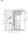
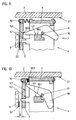
- an angle measuring device is shown, which is on a drive device is attached.
- the drive device is a motor with a mounted shaft 1, the angle of rotation relative to the stator 2 with the angle measuring device should be measured.
- a shaft 1 Measuring standard attached in the form of a graduated disk 3. This attachment can be done by screwing, gluing, pressing or clamping.
- the dividing disc 3 bears a division 3.2 or a coding on a level 3.1, which can be scanned electrically, magnetically, capacitively or inductively.
- the division 3.2 is the position measurement in a conventional manner scanned by a scanning unit 4.
- the scanning unit 4 consists of a Scanning element 5 and a mounting element 6.
- the scanning element 5 is over a guide on the mounting element 6 in the direction of the division 3.2 - that is perpendicular to level 3.1 - slidably mounted.
- the leadership is in the example formed by a threaded bore 8 in the mounting element 6, in the a screw 9 is rotatably mounted. At one end of the screw 9 is fastened the scanning element 5 such that it is relative to the mounting element 6 is displaceable in two defined reference positions. The shift takes place by turning the screw 9, which is why the screw 9 is also used as a positioning element can be designated.
- the first reference position - too Called assembly position - is shown in Figures 1 and 2.
- This State acts a first axially acting stop surface 9.1 of the screw 9 with a first axially acting stop surface 6.1 of the mounting element 6 together.
- a stop surface 9.3 of the screw 9 also acts with a Stop surface 5.3 of the scanning element 5 together.
- the scanning unit 4 with the stator 2 the drive device is torsionally coupled.
- the scanning unit 4 axially to the division level 3.1 in the tube 2.1 until the Scanning element 5 is in contact with the graduated disk 3.
- the scanning unit 4 is attached to the stator 2 by means of the mounting element 6 fixed.
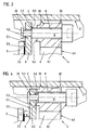
- the screw is now used to set the required scanning distance D. 9 rotated until a second stop surface 6.2 of the mounting element 6 with a second stop surface 9.2 of the screw 9 cooperates.
- This the second reference position - also called the operating position - is shown in FIGS. 3 and 4.
- this second stop surface 6.2 acts Mounting element 6 with the interposition of the disc 5 with the second stop surface 9.2 of the screw 9 together.
- the scanning distance is in practice about 0.5 to 1 mm.
- the scanning element 5 with the help of the screw 9 in two Reference positions is movable relative to the mounting member 6, the Reference positions are specified by parts of the scanning unit 4 itself. Due to the distance between the two reference positions, the scanning distance is D certainly.
- the shift from the first to the second reference position takes place perpendicular to the division plane 3.1, in the angle measuring device shown thus in the direction of the axis of rotation R.
- the stop surfaces 6.1, 6.2, 9.1 and 9.2 run perpendicular to the axis of rotation R.
- the angle measuring device on the basis of which the invention is explained by way of example is an inductively operating device such as that in principle in EP 0 182 085 B1 is described.
- the graduated disk 3 consists of electrically non-conductive Material, and at level 3.1 an incremental division is made spaced apart electrically conductive areas 3.2 applied.
- the scanning element 5 is a circuit board, on the surface of which 5.1 excitation Sensor windings are applied in thin-film technology.
- the board 5 is also disc-shaped.
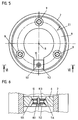
- the relatively large and unstable circuit board 5 defined to be able to move relative to the mounting element 6 three 120 ° offset screws 9 as positioning elements be provided, as can be seen from Figure 5.
- FIGs 2 and 4 is shown schematically how the screw 9 in one Elongated hole 20 of the scanning element 5 (circuit board) is moved.
- the scanning distance there is an axial displacement of the screw 9 in the elongated hole 20.
- Moved when the mounting element 6 is spread the screw 9 radially outwards which is why the longitudinal axis of the elongated hole Starting from the axis R 20 extends radially outward.
- the diameter of the elongated hole 20 corresponds perpendicular to the longitudinal axis exactly the diameter of the engaging screw 9.
- the mounting element 6 is an annular Part whose outer diameter is slightly smaller than the inner diameter of the stator 2. As shown in Figure 5, is in the Mounting element 6 a radially extending slot 10 is provided. This Slot 10 allows the mounting element 6 to be spread apart and thus an increase in the outer diameter. For radial spreading is a spreading element 11 is provided. According to FIG. 6, it consists of a Screw 11.1, with the two arranged one behind the other in the axial direction Clamping elements 11.2 and 11.3 can be moved in opposite directions. The clamping elements 11.2 and 11.3 act with conical surfaces 11.4 and 11.5 of the mounting element 6 together where they rest.
- the stator 2 is the housing or the flange (Motor end shield) of the electric motor.
- the radial clamping means a clamping or spreading into one Direction that is at least largely perpendicular to the axis of rotation R.
- the radial clamping can be on an inner or outer peripheral surface of the Stator 2 act.
- the clamping element can be used to spread the mounting element 6 can also be a conical screw, the cone of which with a corresponding bore cooperates. Furthermore, a radial Clamping also take place by means of an eccentric screw, which in the Slot 10 engages or which directly causes a clamping by in Mounting element is screwed in axially and the eccentric Circumferential surface of the screw head with the tube 2.1 by representing the Screw is brought into contact.
- the actuating element - a screw 11.1 in the example - for introduction the radial clamping is aligned parallel to the axis of rotation R and axially accessible and operable, which considerably simplifies assembly.
- FIGS 2 and 4 an advantageous embodiment of the mounting element 6 is shown schematically.
- the mounting element 6 has projections 30, with which it is in the radial clamping on the tube 2.1 supports.
- another positioning element can also be provided with which two reference positions can be set. Especially It is advantageous if the positioning element is axially accessible and operable is.
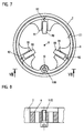
- FIGS. 7 to 10 show a second embodiment of an invention executed angle measuring device shown. The same components are included the same reference numerals as in the first embodiment.
- the graduated disk 3 again has a division 3.2 on the level 3.1 Photoelectric, magnetic, capacitive or inductive can be scanned.
- the sensing element 5 is axially displaceably mounted on the mounting element 6.
- the postponement takes place by actuating a lever 90.
- the positioning element is thus lever 90 in this example.
- three levers 90 offset by 120 ° relative to one another each have an axis of rotation 91 pivotally mounted.
- the first reference position - also called the assembly position - is in FIG. 9 shown.
- the lever 90 defines the first reference position for the scanning element 5.
- the scanning element 5 is supported with a stop surface 5.3 axially from a stop surface 90.3 of the lever 90.
- the scanning element 5 is pushed by a spring 92 to the stop 90.3.
- the lever 90 supports itself with a stop surface 90.1 on a stop surface 6.1 of the mounting element 6 from. As a result, the scanning element 5 is defined in a Distance to the mounting element 6 held.
- the scanning unit 4 is axially in the direction of the division 3.2 guided into the tube 2.1 until the scanning element 5 with the index plate 3 in Contact is there. In this state, the scanning unit 4 is over the Mounting element 6 fixed to the stator 2.
- the three levers 90 are actuated to set the scanning distance D, by pivoting each about its axis of rotation 91.
- the direction of the Actuation is designated by F in FIG. 9.
- the scanning element 5 is in a by operating the lever 90 second reference position moved relative to the mounting member 6. This second The reference position - also called the operating position - is shown in FIG. 10.
- a Stop surface 6.2 of the mounting element 6 acts with a stop surface 5.3 of the scanning element 5 together.
- the mounting element 6 of the second embodiment corresponds to that of the first example, with the difference that the expansion element 11 a Screw is 11.10.
- the screw 11.10 is screwed into the mounting element 6, until the screw head is supported on the mounting element 6.
- the threads of the Screw 11.10 a radial expansion of the slotted annular Mounting element 6 and thus a radial clamping of the scanning unit 4th in the stator 2.
- the stator 2 can in turn be the housing or the flange of an electric motor.
- the circuit board 5 shown as a scanning element instead of the circuit board 5 shown as a scanning element, according to the invention also other inductive scanning elements or also magnetic field sensitive, capacitive or light sensitive sensing elements.
- the scanning element can even a known scanning plate (slit diaphragm) or a Semiconductor substrate with several photosensitive areas.
- the invention can also be used in length measuring devices.
Abstract
Description
Die Erfindung betrifft eine Positionsmeßeinrichtung gemäß dem Oberbegriff
des Anspruches 1 und ein Verfahren zur Montage einer Abtasteinheit einer
Positionsmeßeinrichtung gemäß dem Oberbegriff des Anspruches 11.The invention relates to a position measuring device according to the preamble
of
Bei Positionsmeßeinrichtungen wird eine Maßverkörperung von einem Abtastelement abgetastet. Bei dieser Abtastung werden positionsabhängige elektrische Abtastsignale gewonnen, die einer Folgeelektronik, beispielsweise einem Zähler oder einer numerischen Steuerung zugeführt werden. Die Qualität der Abtastsignale ist abhängig vom Abtastabstand, weshalb es erforderlich ist, das Abtastelement in einem genau definierten Abstand relativ zur Maßverkörperung zu montieren.In position measuring devices, a material measure is made up of a scanning element scanned. With this scanning, position-dependent electrical scanning signals obtained by subsequent electronics, for example a meter or a numerical control. The quality of the scanning signals depends on the scanning distance, which is why is required, the scanning element at a precisely defined distance relative to be mounted to the measuring standard.
In der EP 0 177 711 B1 ist eine Positionsmeßeinrichtung beschrieben, bei der ein Abtastelement in Form einer Abtastteilung in einer Führung zur Einstellung des Abtastabstandes verschiebbar gelagert ist und in jeder Stellung arretierbar ist. Der erforderliche Abtastabstand wird durch eine Abstandsfolie vorgegeben, die während der Montage zwischen Maßverkörperung und Abtastteilung eingefügt wird. Die Verschiebung der Abtastteilung erfolgt bis zur Klemmung der Folie, danach wird die Abtastteilung arretiert und die Folie entfernt.A position measuring device is described in EP 0 177 711 B1, at which a scanning element in the form of a scanning graduation in a guide for adjustment of the scanning distance is slidably mounted and in any position can be locked. The required scanning distance is determined by a spacing film specified during assembly between the measuring standard and the scanning graduation is inserted. The scanning division is shifted up to Clamp the film, then the scanning graduation is locked and the film away.
Nachteilig bei dieser bekannten Positionsmeßeinrichtung ist die Notwendigkeit einer separaten Folie als Abstandshalter sowie das seitliche Entfernen einer geklemmten Folie.The disadvantage of this known position measuring device is the necessity a separate film as a spacer and the side removal a clamped film.
In der EP 0 280 390 A1 und der DE 37 40 744 A1 ist eine Positionsmeßeinrichtung in Form eines Drehgebers bekannt, der keine eigene Lagerung aufweist. Derartige Drehgeber werden als Einbaudrehgeber bezeichnet. Die Relativlage von Abtasteinheit zu Teilscheibe ist bei Einbaudrehgebern erst im angebauten Zustand an die zu messenden Objekte festgelegt. Zur Vereinfachung des Anbaus ist im Drehgeber ein Fixierelement bzw. Verbindungsteil integriert, das mit der Nabe der Teilscheibe in Kontakt steht und während des Anbaus die Relativlage von Abtasteinheit zu Teilscheibe festlegt. Nach erfolgter Montage der Teilscheibe an das eine zu messende Objekt und der Abtasteinheit an das andere zu messende Objekt wird das Fixierelement bzw. das Verbindungsteil entfernt.In EP 0 280 390 A1 and DE 37 40 744 A1 there is a position measuring device known in the form of an encoder, which does not have its own storage having. Such encoders are referred to as built-in encoders. The Relative position of the scanning unit to the indexing disc is the first with built-in encoders fixed in the attached state to the objects to be measured. For simplification of the attachment is a fixing element or connecting part in the encoder integrated, which is in contact with the hub of the indexing disc and determines the relative position of the scanning unit to the indexing disc during the attachment. After the partial disk has been mounted on the object to be measured and the scanning unit to the other object to be measured becomes the fixing element or the connecting part removed.
Der Erfindung liegt die Aufgabe zugrunde, eine Positionsmeßeinrichtung zu schaffen, die einfach aufgebaut ist und mit der der erforderliche Abtastabstand einfach einstellbar ist.The invention has for its object to a position measuring device create that is simple and with the required scanning distance is easily adjustable.
Diese Aufgabe wird durch die Positionsmeßeinrichtung mit den Merkmalen
des Anspruches 1 gelöst.This task is performed by the position measuring device with the features
of
Weiterhin soll ein Verfahren angegeben werden, mit dem eine einfache Montage einer Abtasteinheit einer Positionsmeßeinrichtung gewährleistet ist.Furthermore, a method is to be specified with which a simple Installation of a scanning unit of a position measuring device is guaranteed.
Diese Aufgabe wird durch ein Verfahren gemäß dem Anspruch 11 gelöst. This object is achieved by a method according to claim 11.
Die Vorteile der Erfindung liegen insbesondere darin, daß der Abtastabstand bereits durch die Bauteile der Abtasteinheit selbst festgelegt ist und keine verlierbare Folie benötigt wird.The advantages of the invention are in particular that the scanning distance is already determined by the components of the scanning unit itself and none loss of film is needed.
Anhand von Ausführungsbeispielen wird die Erfindung näher erläutert:The invention is explained in more detail using exemplary embodiments:
- Figur 1Figure 1
- eine erste Positionsmeßeinrichtung in einer Montagestellung im Schnitt,a first position measuring device in one Assembly position in section,
- Figur 2Figure 2
- einen vergrößerten Ausschnitt der Figur 1,2 shows an enlarged section of FIG. 1,
- Figur 3Figure 3
- die Positionsmeßeinrichtung gemäß Figur 1 in der Betriebsstellung,the position measuring device according to Figure 1 in the operating position,
- Figur 4Figure 4
- einen vergrößerten Ausschnitt der Figur 3,3 shows an enlarged section of FIG. 3,
- Figur 5Figure 5
- eine Draufsicht der ersten Positionsmeßeinrichtung in axialer Richtung,a plan view of the first position measuring device in the axial direction,
- Figur 6Figure 6
- einen Schnitt VI-VI der Figur 5,5 shows a section VI-VI of FIG. 5,
- Figur 7Figure 7
- eine zweite Positionsmeßeinrichtung in einer Draufsicht in axialer Richtung,a second position measuring device in one Top view in the axial direction,
- Figur 8Figure 8
- einen Schnitt VIII-VIII der Figur 7,a section VIII-VIII of Figure 7,
- Figur 9Figure 9
- einen vergrößerten Ausschnitt der zweiten Positionsmeßeinrichtung in der Montagestellung und an enlarged section of the second position measuring device in the assembly position and
- Figur 10Figure 10
- einen vergrößerten Ausschnitt der zweiten Positionsmeßeinrichtung in der Betriebsstellung.an enlarged section of the second position measuring device in the operating position.
In Figur 1 ist eine Winkelmeßeinrichtung dargestellt, die an einer Antriebseinrichtung
befestigt ist. Die Antriebseinrichtung ist ein Motor mit einer
gelagerten Welle 1, deren Drehwinkel relativ zu dem Stator 2 mit der Winkelmeßeinrichtung
gemessen werden soll. Hierzu ist an der Welle 1 eine
Maßverkörperung in Form einer Teilscheibe 3 befestigt. Diese Befestigung
kann durch Schrauben, Kleben, Pressen oder Klemmen erfolgen. Die Teilscheibe
3 trägt auf einer Ebene 3.1 eine Teilung 3.2 bzw. eine Codierung,
die lichtelektrisch, magnetisch, kapazitiv oder induktiv abtastbar ist.In Figure 1, an angle measuring device is shown, which is on a drive device
is attached. The drive device is a motor with a
mounted
Die Teilung 3.2 wird bei der Positionsmessung in an sich bekannter Weise
von einer Abtasteinheit 4 abgetastet. Die Abtasteinheit 4 besteht aus einem
Abtastelement 5 und einem Montageelement 6. Das Abtastelement 5 ist über
eine Führung an dem Montageelement 6 in Richtung der Teilung 3.2 - also
senkrecht zur Ebene 3.1 - verschiebbar gelagert. Die Führung wird im Beispiel
durch eine Gewindebohrung 8 im Montageelement 6 gebildet, in der
eine Schraube 9 verdrehbar gelagert ist. An einem Ende der Schraube 9 ist
das Abtastelement 5 derart befestigt, daß es relativ zum Montageelement 6
in zwei definierte Bezugspositionen verschiebbar ist. Die Verschiebung erfolgt
durch Verdrehen der Schraube 9, weshalb die Schraube 9 auch als Positionierelement
bezeichnet werden kann. Die erste Bezugsposition - auch
Montagestellung genannt - ist in den Figuren 1 und 2 dargestellt. In diesem
Zustand wirkt eine erste axial wirkende Anschlagsfläche 9.1 der Schraube 9
mit einer ersten axial wirkenden Anschlagfläche 6.1 des Montageelementes
6 zusammen. Ebenso wirkt eine Anschlagfläche 9.3 der Schraube 9 mit einer
Anschlagfläche 5.3 des Abtastelementes 5 zusammen.The division 3.2 is the position measurement in a conventional manner
scanned by a
In dieser ersten Bezugsposition wird die Abtasteinheit 4 mit dem Stator 2
der Antriebseinrichtung drehsteif gekoppelt. Hierzu wird die Abtasteinheit 4
axial zu der Teilungsebene 3.1 in den Tubus 2.1 geführt, bis das
Abtastelement 5 mit der Teilscheibe 3 in Kontakt steht. In diesem Zustand
wird die Abtasteinheit 4 mittels dem Montageelement 6 an dem Stator 2
fixiert.In this first reference position, the
Zur Einstellung des erforderlichen Abtastabstandes D wird nun die Schraube
9 verdreht, bis eine zweite Anschlagfläche 6.2 des Montageelementes 6 mit
einer zweiten Anschlagfläche 9.2 der Schraube 9 zusammenwirkt. Diese
zweite Bezugsposition - auch Betriebsstellung genannt - ist in den Figuren 3
und 4 dargestellt. Im Beispiel wirkt diese zweite Anschlagfläche 6.2 des
Montageelementes 6 unter Zwischenschaltung der Scheibe 5 mit der
zweiten Anschlagfläche 9.2 der Schraube 9 zusammen. Der Abtastabstand
ist in der Praxis etwa 0,5 bis 1 mm.The screw is now used to set the required scanning distance D.
9 rotated until a second stop surface 6.2 of the
Wesentlich ist, daß das Abtastelement 5 mit Hilfe der Schraube 9 in zwei
Bezugspositionen relativ zum Montageelement 6 bewegbar ist, wobei die
Bezugspositionen durch Teile der Abtasteinheit 4 selbst vorgegeben sind.
Durch den Abstand der beiden Bezugspositionen ist der Abtastabstand D
bestimmt. Die Verschiebung von der ersten zur zweiten Bezugsposition erfolgt
senkrecht zur Teilungsebene 3.1, bei der dargestellten Winkelmeßeinrichtung
somit in Richtung der Drehachse R. Die Anschlagflächen 6.1, 6.2,
9.1 und 9.2 verlaufen senkrecht zur Drehachse R.It is essential that the
Die Winkelmeßeinrichtung, anhand der die Erfindung beispielhaft erläutert
ist, ist eine induktiv arbeitende Einrichtung, wie sie im Prinzip in der EP 0 182
085 B1 beschrieben ist. Die Teilscheibe 3 besteht aus elektrisch nichtleitfähigem
Material, und auf der Ebene 3.1 ist eine inkrementale Teilung aus
voneinander beabstandeten elektrisch leitenden Bereichen 3.2 aufgebracht.
Das Abtastelement 5 ist eine Platine, auf dessen Oberfläche 5.1 Erregerund
Sensorwicklungen in Dünnschichttechnik aufgebracht sind. Die Platine 5
ist ebenfalls scheibenförmig ausgebildet. Um die relativ große und labile Platine
5 definiert relativ zum Montageelement 6 verschieben zu können, können
drei um 120° gegeneinander versetzte Schrauben 9 als Positionierelemente
vorgesehen sein, wie aus Figur 5 ersichtlich ist.The angle measuring device on the basis of which the invention is explained by way of example
is an inductively operating device such as that in principle in EP 0 182
085 B1 is described. The graduated
In der Figur 2 und 4 ist schematisch dargestellt, wie die Schraube 9 in einem
Langloch 20 des Abtastelementes 5 (Platine) bewegt wird. Bei der Einstellung
des Abtastabstandes erfolgt eine axiale Verschiebung der Schraube 9
in dem Langloch 20. Bei der Spreizung des Montageelementes 6 bewegt
sich die Schraube 9 radial nach außen, weshalb die Längsachse des Langloches
von der Achse R ausgehend 20 radial nach außen gerichtet verläuft.
Der Durchmesser des Langloches 20 senkrecht zur Längsachse entspricht
exakt dem Durchmesser der eingreifenden Schraube 9. Durch das Vorsehen
von mehreren - z.B. drei um 120° - versetzten Langlöchern ist gewährleistet,
daß sich die Lage des Abtastelementes 5 bei der Spreizung des Montageelementes
6 nicht ändert.In Figures 2 and 4 is shown schematically how the
Nachfolgend wird eine bevorzugte Variante des Montageelementes 6 beschrieben.
Das Montageelement 6 gemäß den Figuren 1 bis 6 ist ein ringförmiges
Teil, dessen Außendurchmesser geringfügig kleiner ist als der Innendurchmesser
des Stators 2. Wie in Figur 5 dargestellt ist, ist in dem
Montageelement 6 ein radial verlaufender Schlitz 10 vorgesehen. Dieser
Schlitz 10 ermöglicht ein Aufspreizen des Montageelementes 6 und somit
eine Vergrößerung des äußeren Durchmessers. Zur radialen Spreizung ist
ein Spreizelement 11 vorgesehen. Es besteht gemäß Figur 6 aus einer
Schraube 11.1, mit der zwei in axialer Richtung hintereinander angeordnete
Klemmelemente 11.2 und 11.3 gegenläufig bewegbar sind. Die Klemmelemente
11.2 und 11.3 wirken mit konischen Flächen 11.4 und 11.5 des Montageelementes
6 zusammen, wo sie sich abstützen. Durch Drehen der
Schraube 11.1 werden die beiden Klemmelemente 11.2, 11.3 aneinander
gezogen, wobei sich durch die Keilwirkung der Spalt 10 und somit der Außendurchmesser
des Montageelementes 6 vergrößert. Besonders vorteilhaft
ist diese radiale Klemmung zwischen dem Stator 2 und der Abtasteinheit 4,
wenn die Abtasteinheit 4 direkt in einen Tubus 2.1 eines Motors eingesetzt
werden soll, da bei dieser Montage keine Bohrungen am Motor erforderlich
sind. In diesem Fall ist der Stator 2 das Gehäuse oder der Flansch
(Motorlagerschild) des Elektromotors.A preferred variant of the mounting
Die radiale Klemmung bedeutet eine Klemmung bzw. Spreizung in eine
Richtung, die zumindest weitgehend senkrecht zur Drehachse R verläuft. Die
radiale Klemmung kann an einer inneren oder äußeren Umfangsfläche des
Stators 2 wirken.The radial clamping means a clamping or spreading into one
Direction that is at least largely perpendicular to the axis of rotation R. The
radial clamping can be on an inner or outer peripheral surface of the
In nicht gezeigter Weise kann das Klemmelement zur Spreizung des Montageelementes
6 auch eine konische Schraube sein, deren Konus mit einer
korrespondierenden Bohrung zusammenwirkt. Weiterhin kann eine radiale
Klemmung auch mittels einer Exzenterschraube erfolgen, welche in dem
Schlitz 10 eingreift oder welche direkt eine Klemmung bewirkt, indem sie im
Montageelement axial eingeschraubt ist und die exzentrisch verlaufende
Umfangsfläche des Schraubenkopfes mit dem Tubus 2.1 durch Vertreten der
Schraube in Kontakt gebracht wird.In a manner not shown, the clamping element can be used to spread the mounting
Das Betätigungselement - im Beispiel eine Schraube 11.1 - zur Einleitung der radialen Klemmung ist parallel zur Drehachse R ausgerichtet und axial zugänglich und betätigbar, was die Montage erheblich vereinfacht.The actuating element - a screw 11.1 in the example - for introduction the radial clamping is aligned parallel to the axis of rotation R and axially accessible and operable, which considerably simplifies assembly.
In den Figuren 2 und 4 eine vorteilhafte Ausgestaltung des Montageelementes
6 schematisch dargestellt. Das Montageelement 6 besitzt Vorsprünge
30, mit denen es sich bei der radialen Klemmung am Tubus 2.1
abstützt.In Figures 2 and 4 an advantageous embodiment of the mounting
Anstelle der Schraube 9 kann auch ein anderes Positionierelement vorgesehen
sein, mit dem zwei Bezugspositionen einstellbar sind. Besonders
vorteilhaft ist es, wenn das Positionierelement axial zugänglich und betätigbar
ist. Instead of the
In den Figuren 7 bis 10 ist eine zweite Ausführung einer erfindungsgemäß ausgeführten Winkelmeßeinrichtung dargestellt. Gleiche Bauteile sind mit den gleichen Bezugszeichen wie beim ersten Ausführungsbeispiel versehen.FIGS. 7 to 10 show a second embodiment of an invention executed angle measuring device shown. The same components are included the same reference numerals as in the first embodiment.
Die Teilscheibe 3 trägt auf der Ebene 3.1 wiederum eine Teilung 3.2, die
lichtelektrisch, magnetisch, kapazitiv oder induktiv abtastbar ist. Das Abtastelement
5 ist an dem Montagelement 6 axial verschiebbar gelagert. Die Verschiebung
erfolgt durch Betätigen eines Hebels 90. Das Positionierelement
ist in diesem Beispiel somit der Hebel 90. Wie in Figur 7 dargestellt ist, sind
im Montagelement 6 drei um 120° gegeneinander versetzte Hebel 90 über
jeweils eine Drehachse 91 schwenkbar gelagert.The graduated
Die erste Bezugsposition - auch Montagestellung genannt - ist in Figur 9
dargestellt. Der Hebel 90 definiert für das Abtastelement 5 die erste Bezugsposition.
Das Abtastelement 5 stützt sich mit einer Anschlagfläche 5.3 an
einer Anschlagfläche 90.3 des Hebels 90 axial ab. Das Abtastelement 5 wird
mittels einer Feder 92 an den Anschlag 90.3 gedrängt. Der Hebel 90 stützt
sich mit einer Anschlagfläche 90.1 an einer Anschlagfläche 6.1 des Montageelementes
6 ab. Dadurch wird das Abtastelement 5 in einem definierten
Abstand zum Montageelement 6 gehalten.The first reference position - also called the assembly position - is in FIG. 9
shown. The
In diesem Zustand wird die Abtasteinheit 4 axial in Richtung der Teilung 3.2
in den Tubus 2.1 geführt, bis das Abtastelement 5 mit der Teilscheibe 3 in
Kontakt steht. In diesem Zustand wird die Abtasteinheit 4 über das
Montageelement 6 an dem Stator 2 fixiert.In this state, the
Zur Einstellung des Abtastabstandes D werden die drei Hebel 90 betätigt,
indem jeder um seine Drehachse 91 verschwenkt wird. Die Richtung der
Betätigung ist in Figur 9 mit F bezeichnet. In nicht dargestellter Weise
können die drei Hebel auch mit einer Einrichtung gemeinsam betätigt
werden. Das Abtastelement 5 wird durch Betätigen der Hebel 90 in eine
zweite Bezugsposition relativ zum Montageelement 6 bewegt. Diese zweite
Bezugsposition - auch Betriebsstellung genannt - ist in Figur 10 gezeigt. Eine
Anschlagfläche 6.2 des Montageelementes 6 wirkt mit einer Anschlagfläche
5.3 des Abtastelementes 5 zusammen.The three
Das Montageelement 6 des zweiten Ausführungsbeispiels entspricht dem
des ersten Beispiels, mit dem Unterschied, daß das Spreizelement 11 eine
Schraube 11.10 ist. Die Schraube 11.10 wird in das Montageelement 6 eingeschraubt,
bis sich der Schraubenkopf am Montageelement 6 abstützt.
Durch Weiterdrehen der Schraube 11.10 bewirken die Gewindegänge der
Schraube 11.10 ein radiales Aufspreizen des geschlitzten ringförmigen
Montageelementes 6 und somit eine radiale Klemmung der Abtasteinheit 4
im Stator 2. Der Stator 2 kann wiederum das Gehäuse oder der Flansch
eines Elektromotors sein.The mounting
Anstelle der dargestellten Platine 5 als Abtastelement können erfindungsgemäß
auch andere induktiven Abtastelemente oder aber auch magnetfeldempfindliche,
kapazitive oder lichtempfindliche Abtastelemente montiert werden.
Bei lichtelektrischen Positionsmeßeinrichtungen kann das Abtastelement
auch nur eine an sich bekannte Abtastplatte (Schlitzblende) oder ein
Halbleitersubstrat mit mehreren lichtempfindlichen Bereichen sein.Instead of the
Die Erfindung ist auch bei Längenmeßeinrichtungen einsetzbar.The invention can also be used in length measuring devices.
Claims (11)
- A position measuring device for measuring the relative position between two objects (1, 2) movable relative to one another, in which a measuring entity (3) is sensed by a sensing element (5) of a sensing unit (4), wherein the measuring entity (3) is fixed to the first object (1) and the sensing unit (4) can be fixed to the second object (2) by means of a mounting element (6), characterized in that a positioning means (9; 90) is integrated in the sensing unit (4) and the sensing element (5) can be moved thereby from a first reference position into a second reference position, in that the reference positions are predetermined by the cooperation of elements (5, 6, 9; 5, 6, 90) integrated in the sensing unit (4), whereby the sensing distance (D) between the measuring entity (3) and the sensing element (5) is determined by the movement.
- A position measuring device according to claim 1, characterized in that the measuring entity (3) is a disc (3) fixed on a shaft (1) for rotation about an axis of rotation (R), with a graduation (3.2) provided on its surface (3.1) lying perpendicular to the axis of rotation (R), and in that the sensing element (5) is guided on the mounting element (6) by the positioning means (9; 90) for axial movement.
- A position measuring device according to claim 1 or 2, characterized in that the mounting element (6) has first stop surface (6.1), with which a first stop surface (9.1; 90.1) of the position means (9; 90) cooperates in the first reference position, and in that the positioning means (9; 90) and/or the mounting element (6) have second stop surfaces (6.2, 9.2), which determine the second reference position.
- A position measuring device according to claim 3, characterized in that the positioning means is a screw (9) which is axial movable through a thread (8) in the mounting element (6).
- A position measuring device according to claim 3, characterized in that the positioning means is a lever (90) which is pivotally mounted in the mounting element (6).
- A position measuring device according to any of claims 1 to 5, characterized in that the positioning means (9) is axially accessible for actuation.
- A position measuring device according to any of claims 2 to 6, characterized in that the mounting element (6) comprises a clamp element (11) for radial clamping between the mounting element (6) and the second object (2).
- A position measuring device according to claim 7, characterized in that the clamp element (11) is aligned parallel to the axis of rotation (R) and is accessible and operable in this axial direction for the clamping.
- A position measuring device according to claim 7 or 8, characterized in that the second object (2) has a mounting tube (2.1) on whose inner peripheral surface the mounting element (6) can be radially clamped.
- A position measuring device according to claim 9, characterized in that the mounting tube (2.1) is a component of a motor (2) on whose shaft (1) the disc (3) is mounted torsionally stiffly.
- A method of mounting a sensing unit (4) of a position measuring device, in which a measuring entity (3) is fixed on a first object (1) and the sensing unit (4) for sensing the measuring entity (3) is fixed by means of the following method steps on a second object (2):a. a sensing element (5) is fixed on a mounting element (6) by means of a positioning means (9; 90) in a first reference position,b. the sensing unit (4) consisting of the sensing element (5), the mounting element (6) and the positioning means (9; 90) is moved in the direction of the measuring entity (3), until an element of the sensing unit is in contact with the measuring entity (3) or a support of the measuring entity (3),c. the mounting element (6) is fixed to a second object,d. the sensing element (5) is moved by means of the positioning means (9; 90) on the mounting element (6) to a second reference position, whereby the sensing distance (D) between the measuring entity (3) and the sensing element (5) is predetermined by this movement.
Applications Claiming Priority (2)
| Application Number | Priority Date | Filing Date | Title |
|---|---|---|---|
| DE19645605A DE19645605A1 (en) | 1996-11-06 | 1996-11-06 | Position measuring device and method for mounting a scanning element of a position measuring device |
| DE19645605 | 1996-11-06 |
Publications (2)
| Publication Number | Publication Date |
|---|---|
| EP0841539A1 EP0841539A1 (en) | 1998-05-13 |
| EP0841539B1 true EP0841539B1 (en) | 2001-03-21 |
Family
ID=7810718
Family Applications (1)
| Application Number | Title | Priority Date | Filing Date |
|---|---|---|---|
| EP97119215A Expired - Lifetime EP0841539B1 (en) | 1996-11-06 | 1997-11-04 | Position measuring device and process for mounting a pickup-unit in such a measuring device |
Country Status (4)
| Country | Link |
|---|---|
| US (1) | US6002126A (en) |
| EP (1) | EP0841539B1 (en) |
| AT (1) | ATE199979T1 (en) |
| DE (2) | DE19645605A1 (en) |
Cited By (1)
| Publication number | Priority date | Publication date | Assignee | Title |
|---|---|---|---|---|
| DE102004040244A1 (en) * | 2004-08-13 | 2006-02-23 | Hübner Elektromaschinen GmbH | encoders |
Families Citing this family (15)
| Publication number | Priority date | Publication date | Assignee | Title |
|---|---|---|---|---|
| JP3081178B2 (en) * | 1997-10-03 | 2000-08-28 | バンドー化学株式会社 | Accelerator position sensor |
| JP4174096B2 (en) * | 1998-03-31 | 2008-10-29 | ソニーマニュファクチュアリングシステムズ株式会社 | Position detection device |
| DE19836003A1 (en) | 1998-08-08 | 2000-02-10 | Heidenhain Gmbh Dr Johannes | Method for mounting a position measuring device and positioning means for mounting |
| ATE371167T1 (en) | 2000-02-17 | 2007-09-15 | Heidenhain Gmbh Dr Johannes | POSITION MEASURING DEVICE AND METHOD FOR OPERATING THE SAME |
| DE10022555A1 (en) * | 2000-05-10 | 2001-11-15 | Heidenhain Gmbh Dr Johannes | Angle measuring device |
| DE10117197B4 (en) * | 2001-04-05 | 2014-10-09 | Anton Rodi | encoders |
| DE102005013364A1 (en) * | 2004-05-18 | 2005-12-15 | Dr. Johannes Heidenhain Gmbh | Position measuring device |
| DE102004047458A1 (en) * | 2004-09-30 | 2006-04-06 | Dr. Johannes Heidenhain Gmbh | Position measuring device |
| DE502006003671D1 (en) * | 2006-09-04 | 2009-06-18 | Sick Stegmann Gmbh | Rotary encoder with mounting aid |
| EP2138806A1 (en) * | 2008-06-27 | 2009-12-30 | SICK STEGMANN GmbH | Position measuring device |
| JP6291167B2 (en) * | 2013-03-21 | 2018-03-14 | ハイデンハイン株式会社 | Linear encoder and linear encoder adjustment method |
| JP6657005B2 (en) * | 2016-04-27 | 2020-03-04 | 株式会社ミツトヨ | Linear gauge |
| ES2701307T3 (en) * | 2016-06-07 | 2019-02-21 | Heidenhain Gmbh Dr Johannes | Materialized measurement as well as position measuring device |
| JP6831483B2 (en) * | 2017-05-31 | 2021-02-17 | フラバ ベスローテン ヴェンノーツハップFraba B.V. | A sensor unit for a rotation angle measurement system and a rotation angle measurement system including such a sensor unit. |
| EP3839443B1 (en) * | 2019-12-16 | 2022-06-08 | Sick Ag | Encoder device and method for determining a kinematic value |
Family Cites Families (8)
| Publication number | Priority date | Publication date | Assignee | Title |
|---|---|---|---|---|
| DE2611459C3 (en) * | 1976-03-18 | 1978-09-21 | Dr. Johannes Heidenhain Gmbh, 8225 Traunreut | Length measuring device |
| DE3437515C2 (en) * | 1984-10-12 | 1986-08-14 | Dr. Johannes Heidenhain Gmbh, 8225 Traunreut | Position measuring device |
| IE55855B1 (en) * | 1984-10-19 | 1991-01-30 | Kollmorgen Ireland Ltd | Position and speed sensors |
| SE455536B (en) * | 1986-12-02 | 1988-07-18 | Leine & Linde Ab | PROCEDURE AND DEVICE FOR TRANSFER OF ADJUSTED MEDICINE FROM ADJUSTFIXTURE TO EXTERNAL DRIVEN FOR AN ANGLE METHOD DEVICE |
| US4794250A (en) * | 1987-02-27 | 1988-12-27 | Hewlett-Packard Company | Self-gapping optical encoder |
| DE8717824U1 (en) * | 1987-04-23 | 1990-05-03 | Dr. Johannes Heidenhain Gmbh, 8225 Traunreut, De | |
| DE4001848C1 (en) * | 1990-01-23 | 1991-05-16 | Dr. Johannes Heidenhain Gmbh, 8225 Traunreut, De | |
| US5103917A (en) * | 1990-04-27 | 1992-04-14 | Sukup Manufacturing Company | Adjustable calibration assembly for a guidance system |
-
1996
- 1996-11-06 DE DE19645605A patent/DE19645605A1/en not_active Withdrawn
-
1997
- 1997-11-04 US US08/964,294 patent/US6002126A/en not_active Expired - Fee Related
- 1997-11-04 AT AT97119215T patent/ATE199979T1/en not_active IP Right Cessation
- 1997-11-04 EP EP97119215A patent/EP0841539B1/en not_active Expired - Lifetime
- 1997-11-04 DE DE59703177T patent/DE59703177D1/en not_active Expired - Lifetime
Cited By (1)
| Publication number | Priority date | Publication date | Assignee | Title |
|---|---|---|---|---|
| DE102004040244A1 (en) * | 2004-08-13 | 2006-02-23 | Hübner Elektromaschinen GmbH | encoders |
Also Published As
| Publication number | Publication date |
|---|---|
| JPH1123205A (en) | 1999-01-29 |
| DE19645605A1 (en) | 1998-05-07 |
| EP0841539A1 (en) | 1998-05-13 |
| US6002126A (en) | 1999-12-14 |
| JP3954705B2 (en) | 2007-08-08 |
| DE59703177D1 (en) | 2001-04-26 |
| ATE199979T1 (en) | 2001-04-15 |
Similar Documents
| Publication | Publication Date | Title |
|---|---|---|
| EP0841539B1 (en) | Position measuring device and process for mounting a pickup-unit in such a measuring device | |
| EP0353395B1 (en) | Angle-measuring device | |
| EP1927823B1 (en) | Rotary encoder | |
| DE10037211B4 (en) | Steering wheel position sensor | |
| EP1927824B1 (en) | Rotary encoder | |
| DE3935261A1 (en) | MULTIPLE ROTATION SHAFT POSITION SENSOR WITH GAME COMPENSATION | |
| EP0557564B1 (en) | Mounting device for an angular position encoder | |
| DE3441429C2 (en) | ||
| DE3719731A1 (en) | DEVICE FOR MEASURING A DISPLACEMENT | |
| EP0177711A2 (en) | Position-measuring device | |
| DE19836003A1 (en) | Method for mounting a position measuring device and positioning means for mounting | |
| DE102006036746B4 (en) | Position measuring device | |
| EP0973014A1 (en) | Rotational position measuring device and its procedure to mount it | |
| DE102005050016A1 (en) | Multi-turn shaft encoder used in machine tools and industrial robots for measuring angle positions comprises a fixing element fixed to a support element | |
| DE102019106572B4 (en) | Force measuring device, gear and actuator and use of a force measuring device | |
| CH661980A5 (en) | SWITCH FOR A TOOTH-RANK PROFILE MEASURING DEVICE FOR DETERMINING THE TOOTH-FLANGE SURFACE ROUGHNESS. | |
| DE202006010183U1 (en) | Angle measuring device e.g. for rotary encoder, has locking part which can be moved to locking position to limit axial spring movement between machine part and structural unit | |
| DE102019124972A1 (en) | Sensor arrangement for detecting a steering torque and an absolute angular position and sensor device with this sensor arrangement | |
| EP0585655A1 (en) | Method and device for position control of a movable member | |
| EP1452836B1 (en) | Angular displacement sensing apparatus | |
| DE19612830C1 (en) | Drive pedal transmission with potentiometer as sensor | |
| DE10137014B4 (en) | Position measuring device | |
| DE2501230C2 (en) | Device for scanning the speed of a vehicle wheel | |
| DE4432827C2 (en) | Positioning device | |
| DE10145313A1 (en) | Sensor device for generation of a control signal from the relative position of two motor vehicle components that move relative to each other has accuracy increased by use of a varying gap between moving control member and magnets |
Legal Events
| Date | Code | Title | Description |
|---|---|---|---|
| PUAI | Public reference made under article 153(3) epc to a published international application that has entered the european phase |
Free format text: ORIGINAL CODE: 0009012 |
|
| AK | Designated contracting states |
Kind code of ref document: A1 Designated state(s): AT CH DE FR GB IT LI |
|
| 17P | Request for examination filed |
Effective date: 19981113 |
|
| AKX | Designation fees paid |
Free format text: AT CH DE FR GB IT LI |
|
| RBV | Designated contracting states (corrected) |
Designated state(s): AT CH DE FR GB IT LI |
|
| 17Q | First examination report despatched |
Effective date: 19990118 |
|
| GRAG | Despatch of communication of intention to grant |
Free format text: ORIGINAL CODE: EPIDOS AGRA |
|
| GRAG | Despatch of communication of intention to grant |
Free format text: ORIGINAL CODE: EPIDOS AGRA |
|
| GRAH | Despatch of communication of intention to grant a patent |
Free format text: ORIGINAL CODE: EPIDOS IGRA |
|
| GRAH | Despatch of communication of intention to grant a patent |
Free format text: ORIGINAL CODE: EPIDOS IGRA |
|
| ITF | It: translation for a ep patent filed |
Owner name: DE DOMINICIS & MAYER S.R.L. |
|
| GRAA | (expected) grant |
Free format text: ORIGINAL CODE: 0009210 |
|
| AK | Designated contracting states |
Kind code of ref document: B1 Designated state(s): AT CH DE FR GB IT LI |
|
| REF | Corresponds to: |
Ref document number: 199979 Country of ref document: AT Date of ref document: 20010415 Kind code of ref document: T |
|
| REG | Reference to a national code |
Ref country code: CH Ref legal event code: NV Representative=s name: TROESCH SCHEIDEGGER WERNER AG Ref country code: CH Ref legal event code: EP |
|
| REF | Corresponds to: |
Ref document number: 59703177 Country of ref document: DE Date of ref document: 20010426 |
|
| ET | Fr: translation filed | ||
| GBT | Gb: translation of ep patent filed (gb section 77(6)(a)/1977) |
Effective date: 20010530 |
|
| REG | Reference to a national code |
Ref country code: GB Ref legal event code: IF02 |
|
| PLBE | No opposition filed within time limit |
Free format text: ORIGINAL CODE: 0009261 |
|
| STAA | Information on the status of an ep patent application or granted ep patent |
Free format text: STATUS: NO OPPOSITION FILED WITHIN TIME LIMIT |
|
| 26N | No opposition filed | ||
| PGFP | Annual fee paid to national office [announced via postgrant information from national office to epo] |
Ref country code: AT Payment date: 20081114 Year of fee payment: 12 |
|
| PG25 | Lapsed in a contracting state [announced via postgrant information from national office to epo] |
Ref country code: AT Free format text: LAPSE BECAUSE OF NON-PAYMENT OF DUE FEES Effective date: 20091104 |
|
| PGFP | Annual fee paid to national office [announced via postgrant information from national office to epo] |
Ref country code: IT Payment date: 20101122 Year of fee payment: 14 |
|
| PGFP | Annual fee paid to national office [announced via postgrant information from national office to epo] |
Ref country code: FR Payment date: 20111130 Year of fee payment: 15 |
|
| REG | Reference to a national code |
Ref country code: FR Ref legal event code: ST Effective date: 20130731 |
|
| PG25 | Lapsed in a contracting state [announced via postgrant information from national office to epo] |
Ref country code: IT Free format text: LAPSE BECAUSE OF NON-PAYMENT OF DUE FEES Effective date: 20121104 |
|
| PG25 | Lapsed in a contracting state [announced via postgrant information from national office to epo] |
Ref country code: FR Free format text: LAPSE BECAUSE OF NON-PAYMENT OF DUE FEES Effective date: 20121130 |
|
| PGFP | Annual fee paid to national office [announced via postgrant information from national office to epo] |
Ref country code: DE Payment date: 20141119 Year of fee payment: 18 Ref country code: GB Payment date: 20141119 Year of fee payment: 18 Ref country code: CH Payment date: 20141119 Year of fee payment: 18 |
|
| REG | Reference to a national code |
Ref country code: DE Ref legal event code: R119 Ref document number: 59703177 Country of ref document: DE |
|
| REG | Reference to a national code |
Ref country code: CH Ref legal event code: PL |
|
| GBPC | Gb: european patent ceased through non-payment of renewal fee |
Effective date: 20151104 |
|
| PG25 | Lapsed in a contracting state [announced via postgrant information from national office to epo] |
Ref country code: CH Free format text: LAPSE BECAUSE OF NON-PAYMENT OF DUE FEES Effective date: 20151130 Ref country code: LI Free format text: LAPSE BECAUSE OF NON-PAYMENT OF DUE FEES Effective date: 20151130 |
|
| PG25 | Lapsed in a contracting state [announced via postgrant information from national office to epo] |
Ref country code: GB Free format text: LAPSE BECAUSE OF NON-PAYMENT OF DUE FEES Effective date: 20151104 Ref country code: DE Free format text: LAPSE BECAUSE OF NON-PAYMENT OF DUE FEES Effective date: 20160601 |