EP0841142A2 - Moule d'injection - Google Patents
Moule d'injection Download PDFInfo
- Publication number
- EP0841142A2 EP0841142A2 EP97890219A EP97890219A EP0841142A2 EP 0841142 A2 EP0841142 A2 EP 0841142A2 EP 97890219 A EP97890219 A EP 97890219A EP 97890219 A EP97890219 A EP 97890219A EP 0841142 A2 EP0841142 A2 EP 0841142A2
- Authority
- EP
- European Patent Office
- Prior art keywords
- nozzle
- injection
- nozzle tip
- injection mold
- mold according
- Prior art date
- Legal status (The legal status is an assumption and is not a legal conclusion. Google has not performed a legal analysis and makes no representation as to the accuracy of the status listed.)
- Granted
Links
- 238000002347 injection Methods 0.000 title claims abstract description 39
- 239000007924 injection Substances 0.000 title claims abstract description 39
- 239000000463 material Substances 0.000 claims abstract description 19
- 238000000465 moulding Methods 0.000 claims abstract description 8
- 238000001816 cooling Methods 0.000 claims description 7
- 239000004033 plastic Substances 0.000 claims description 3
- 229920003023 plastic Polymers 0.000 claims description 3
- 229920001187 thermosetting polymer Polymers 0.000 claims description 3
- 230000036316 preload Effects 0.000 claims 1
- 239000007921 spray Substances 0.000 description 8
- 238000004519 manufacturing process Methods 0.000 description 4
- 238000007789 sealing Methods 0.000 description 4
- 238000005266 casting Methods 0.000 description 2
- 238000010276 construction Methods 0.000 description 2
- 239000002826 coolant Substances 0.000 description 2
- 230000002349 favourable effect Effects 0.000 description 2
- 238000010438 heat treatment Methods 0.000 description 2
- 238000009413 insulation Methods 0.000 description 2
- 239000000243 solution Substances 0.000 description 2
- RTAQQCXQSZGOHL-UHFFFAOYSA-N Titanium Chemical compound [Ti] RTAQQCXQSZGOHL-UHFFFAOYSA-N 0.000 description 1
- 238000001746 injection moulding Methods 0.000 description 1
- 230000003993 interaction Effects 0.000 description 1
- 238000003754 machining Methods 0.000 description 1
- 238000000034 method Methods 0.000 description 1
- 230000002093 peripheral effect Effects 0.000 description 1
- 229920001296 polysiloxane Polymers 0.000 description 1
- 239000004810 polytetrafluoroethylene Substances 0.000 description 1
- 229920001343 polytetrafluoroethylene Polymers 0.000 description 1
- 239000012815 thermoplastic material Substances 0.000 description 1
- 229910052719 titanium Inorganic materials 0.000 description 1
- 239000010936 titanium Substances 0.000 description 1
Images


Classifications
-
- B—PERFORMING OPERATIONS; TRANSPORTING
- B29—WORKING OF PLASTICS; WORKING OF SUBSTANCES IN A PLASTIC STATE IN GENERAL
- B29C—SHAPING OR JOINING OF PLASTICS; SHAPING OF MATERIAL IN A PLASTIC STATE, NOT OTHERWISE PROVIDED FOR; AFTER-TREATMENT OF THE SHAPED PRODUCTS, e.g. REPAIRING
- B29C45/00—Injection moulding, i.e. forcing the required volume of moulding material through a nozzle into a closed mould; Apparatus therefor
- B29C45/17—Component parts, details or accessories; Auxiliary operations
- B29C45/26—Moulds
- B29C45/27—Sprue channels ; Runner channels or runner nozzles
- B29C45/2756—Cold runner channels
-
- B—PERFORMING OPERATIONS; TRANSPORTING
- B29—WORKING OF PLASTICS; WORKING OF SUBSTANCES IN A PLASTIC STATE IN GENERAL
- B29C—SHAPING OR JOINING OF PLASTICS; SHAPING OF MATERIAL IN A PLASTIC STATE, NOT OTHERWISE PROVIDED FOR; AFTER-TREATMENT OF THE SHAPED PRODUCTS, e.g. REPAIRING
- B29C45/00—Injection moulding, i.e. forcing the required volume of moulding material through a nozzle into a closed mould; Apparatus therefor
- B29C45/17—Component parts, details or accessories; Auxiliary operations
- B29C45/26—Moulds
- B29C45/27—Sprue channels ; Runner channels or runner nozzles
- B29C45/278—Nozzle tips
-
- B—PERFORMING OPERATIONS; TRANSPORTING
- B29—WORKING OF PLASTICS; WORKING OF SUBSTANCES IN A PLASTIC STATE IN GENERAL
- B29C—SHAPING OR JOINING OF PLASTICS; SHAPING OF MATERIAL IN A PLASTIC STATE, NOT OTHERWISE PROVIDED FOR; AFTER-TREATMENT OF THE SHAPED PRODUCTS, e.g. REPAIRING
- B29C45/00—Injection moulding, i.e. forcing the required volume of moulding material through a nozzle into a closed mould; Apparatus therefor
- B29C45/17—Component parts, details or accessories; Auxiliary operations
- B29C45/26—Moulds
- B29C45/27—Sprue channels ; Runner channels or runner nozzles
- B29C2045/2764—Limited contact between nozzle and mould
-
- B—PERFORMING OPERATIONS; TRANSPORTING
- B29—WORKING OF PLASTICS; WORKING OF SUBSTANCES IN A PLASTIC STATE IN GENERAL
- B29C—SHAPING OR JOINING OF PLASTICS; SHAPING OF MATERIAL IN A PLASTIC STATE, NOT OTHERWISE PROVIDED FOR; AFTER-TREATMENT OF THE SHAPED PRODUCTS, e.g. REPAIRING
- B29C45/00—Injection moulding, i.e. forcing the required volume of moulding material through a nozzle into a closed mould; Apparatus therefor
- B29C45/17—Component parts, details or accessories; Auxiliary operations
- B29C45/26—Moulds
- B29C45/27—Sprue channels ; Runner channels or runner nozzles
- B29C2045/2796—Axially movable nozzles or nozzle tips
-
- B—PERFORMING OPERATIONS; TRANSPORTING
- B29—WORKING OF PLASTICS; WORKING OF SUBSTANCES IN A PLASTIC STATE IN GENERAL
- B29K—INDEXING SCHEME ASSOCIATED WITH SUBCLASSES B29B, B29C OR B29D, RELATING TO MOULDING MATERIALS OR TO MATERIALS FOR MOULDS, REINFORCEMENTS, FILLERS OR PREFORMED PARTS, e.g. INSERTS
- B29K2021/00—Use of unspecified rubbers as moulding material
- B29K2021/006—Thermosetting elastomers
Definitions
- the invention relates to an injection mold according to the preamble of patent claim 1.
- Thermosetting materials in the sense of the invention are essentially plastics that solidify at higher temperatures, or vulcanizing, elastomeric materials, such as silicone or rubber. Such plastics are injected through a spray nozzle into a mold cavity during processing at low temperature, and vulcanize there under the influence of heat to the desired injection molded part. This mold nest is in a hot mold plate. Since the spray nozzle extends into the hot mold plate, measures must be taken to keep the temperature of the spray nozzle low. Otherwise the material would already vulcanize in the spray nozzle and block it.
- the spray nozzle ranges from a cold mold plate to an insulating plate and a heating plate to the hot mold plate. It is arranged in a bore and is generally insulated from the hot molding plate. The most effective way to remove such insulation is through an air gap.
- a mold for injection molding is known in which a pressure piece is inserted between the spray nozzle and the mold plate.
- the sealing between the spray nozzle and the pressure piece and between the pressure piece and the molding plate takes place in each case either by the abutment of two end faces against one another or by a close fit between two peripheral faces. In this way it is particularly prevented that the gap between the spray nozzle and the pressure piece or between the pressure piece and the molding plate cannot fill with the material.
- the heat transfer between the mold plate and the nozzle can be kept relatively low in this known arrangement by means of an appropriate structural design and by the choice of suitable materials.
- it is disadvantageous that the sealing between the components requires machining with the highest accuracy and close tolerances.
- the temperature differences between the individual components must not be too large to avoid different thermal expansions. Therefore, the solution disclosed in this document is very complex and involves a complicated production.
- an injection mold is known from AT-B 401 253, in which an antechamber is provided, into which the injection nozzle opens.
- the antechamber is intended to fill with casting material during injection and thereby form an insulating layer.
- a disadvantage of this device is the danger that the material in the antechamber vulcanized due to the heat transfer from the mold plate and that an already vulcanized material is entrained into the mold cavity during the next casting, which leads to a reduction in the quality of the injection molded part.
- thermoplastic materials are known from EP-A 344 381, in which an intermediate piece is provided to improve the seal.
- an intermediate piece is provided to improve the seal.
- such a nozzle cannot be used for thermosetting materials.
- the object of the present invention is to avoid the above disadvantages and to provide an injection mold which is simple to manufacture and which enables safe operation under various operating conditions.
- the heat transfer by heat conduction is reduced on the one hand and a secure seal can be achieved on the other hand by the increased surface pressure. It is particularly advantageous that it is no longer necessary to use special materials such as titanium or the like for the nozzle tip.
- the seat surface is spherical in the area of the molding plate. Especially in interaction With an equally spherical nozzle tip, the radius of curvature of which is different from that of the seat surface, favorable results can be achieved.
- the nozzle tip can be designed as a wear part that is replaced at the end of its service life.
- the contact pressure of the nozzle tip on the seat can be achieved by various measures.
- a constant contact pressure can be achieved by means of a seal or appropriate springs.
- the nozzle tip is designed to be movable with respect to the nozzle, as a result of which the nozzle tip can also be easily replaced.
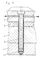
- FIGS. 5 and 6 show details of further embodiment variants of the invention in a longitudinal section.
- a shaped plate 1, a heating plate 2, a temperature protection plate 3 and a cooling plate 4 are arranged one above the other.
- a nozzle 5 is arranged in a bore extending through these components; a mold cavity, which is located after the mold plate 1, is indicated schematically by 6.
- the mold plate 1 has a short injection channel 7, which opens into the mold cavity 6 via an injection opening 8.
- the nozzle 5 is provided in a manner known per se with cooling channels 9 which extend in the form of a two-start screw on the circumference of the nozzle 5.
- a channel 10 for a cooling medium is provided in the cooling plate 4, which channel 10 is connected to the cooling channels 9 of the nozzle 5.
- the nozzle 5 is sealed off from a feed unit 11 (not shown in more detail) by means of a seal 12 which is made, for example, of PTFE.
- This seal 12 has sufficient elasticity to always be for one to ensure appropriate contact pressure of the nozzle tip 15 on the mold plate 1.
- the seal 12 is in all operating conditions at a well-defined temperature, namely that of the cooling plate, which is also the temperature of the nozzle in this area.
- the material of the seal 12 can be optimally designed for this temperature.
- the elasticity of the seal 12 is sufficiently large to be able to compensate for any different thermal expansion of the nozzle 5 compared to the components 1, 2, 3 and 4 in which it is installed.
- FIG. 2 differs from that of FIG. 1 in that in the area of the feed opening 13 for the material, the nozzle 5 has a conically enlarged inlet section 14. In this way, the pressure of the material to be injected is converted into a downward axial force which presses the nozzle 5 against the mold plate 1.
- FIG. 3 is essentially analogous to that of FIG. 2 in its mode of operation. What is different, however, is that the nozzle tip 15a is designed as a separate component that is movable in the axial direction relative to the actual nozzle 5.
- the nozzle tip 15a in turn has a conical inlet opening 16 which in turn converts the pressure of the material to be injected into an axial force which acts on the nozzle tip 15a.
- the advantage of this embodiment variant lies in the easy interchangeability of the nozzle tip 15a.
- a plate spring 17 is provided, which biases the nozzle 5 downwards in order to generate the force which is necessary to ensure a reliable sealing of the nozzle 5 with respect to the mold plate 1.
- FIG. 5 shows the area of the nozzle tip in detail for better understanding. It can be seen that at the end of the injection channel 7, a seat 18 is formed in the mold plate 1, which is spherical around the injection channel 7, with a radius of curvature R. A conical section 19 follows this seat 18.
- the nozzle tip 15 is also spherical, with a radius of curvature r that is smaller than the radius of curvature R of the seat surface 18. In this way, there is contact between the nozzle tip 15 and seat surface 18 along a circular line. A gap 20 in the remaining sections is used for thermal insulation.
- a centering collar 21 is also formed on the nozzle 5, which is free to minimize the heat transfer from the mold plate 1.
- FIG. 6 shows an embodiment variant in which the nozzle tip 15b is designed as an exchangeable wear part.
- the present invention enables a robust and wear-resistant construction of an injection mold with low demands on the manufacturing tolerances.
- the injection point which lies directly in the mold plate and is not part of the nozzle, can be kept extremely small, which enables injection on the thinnest wall thicknesses.
- the simple structure of the invention enables a closed arrangement of the nozzle and the hot mold plate, but without being in direct contact with the mold cavity and without the connection of an additional sleeve made of special materials.
Landscapes
- Engineering & Computer Science (AREA)
- Manufacturing & Machinery (AREA)
- Mechanical Engineering (AREA)
- Moulds For Moulding Plastics Or The Like (AREA)
- Diaphragms For Electromechanical Transducers (AREA)
- Pens And Brushes (AREA)
- Injection Moulding Of Plastics Or The Like (AREA)
- Pharmaceuticals Containing Other Organic And Inorganic Compounds (AREA)
- Non-Silver Salt Photosensitive Materials And Non-Silver Salt Photography (AREA)
- Surgical Instruments (AREA)
Applications Claiming Priority (3)
| Application Number | Priority Date | Filing Date | Title |
|---|---|---|---|
| AT193996 | 1996-11-06 | ||
| AT0193996A ATA193996A (de) | 1996-11-06 | 1996-11-06 | Spritzgussform |
| AT1939/96 | 1996-11-06 |
Publications (3)
| Publication Number | Publication Date |
|---|---|
| EP0841142A2 true EP0841142A2 (fr) | 1998-05-13 |
| EP0841142A3 EP0841142A3 (fr) | 1999-06-16 |
| EP0841142B1 EP0841142B1 (fr) | 2000-03-01 |
Family
ID=3524303
Family Applications (1)
| Application Number | Title | Priority Date | Filing Date |
|---|---|---|---|
| EP97890219A Expired - Lifetime EP0841142B1 (fr) | 1996-11-06 | 1997-11-04 | Moule d'injection |
Country Status (7)
| Country | Link |
|---|---|
| EP (1) | EP0841142B1 (fr) |
| AT (2) | ATA193996A (fr) |
| DE (1) | DE59701165D1 (fr) |
| DK (1) | DK0841142T3 (fr) |
| ES (1) | ES2144838T3 (fr) |
| GR (1) | GR3033377T3 (fr) |
| PT (1) | PT841142E (fr) |
Cited By (8)
| Publication number | Priority date | Publication date | Assignee | Title |
|---|---|---|---|---|
| EP0995573A1 (fr) * | 1998-10-21 | 2000-04-26 | Bruno Meroni | Système buse d'injection/moule pour mouler par injection des polymères, silicones ou matière thermodurcissable |
| EP1029647A1 (fr) | 1999-02-18 | 2000-08-23 | Elast Kunststoffverarbeitungs-GmbH & Co. KEG | Buse d'injection |
| WO2001087570A1 (fr) * | 2000-05-19 | 2001-11-22 | Husky Injection Molding Systems Ltd. | Appareil d"etancheite a canaux chauffants ameliore et procede associe |
| EP1384560A1 (fr) * | 2002-07-26 | 2004-01-28 | Bruno Meroni | Moule pour l'injection de polymères, silicones ou matières thermodurcissables avec une buse d'injection auto-nettoyante et buse d'injection pour ce moule |
| EP1813411A2 (fr) * | 2006-01-31 | 2007-08-01 | Incoe International, Inc. | Joints résistants pour installations à mouler par injection |
| US7614869B2 (en) | 2007-05-08 | 2009-11-10 | Mold-Masters (2007) Limited | Manifold nozzle connection for an injection molding system |
| DE102014210332A1 (de) * | 2014-06-02 | 2015-12-03 | AWETIS Engineering + Manufacturing GmbH | Einspritzdüse zum Einbringen von Spritzgut in eine Spritzgußform |
| CN113853298A (zh) * | 2019-04-11 | 2021-12-28 | 康宁公司 | 使用cte不匹配改进的边缘强度 |
Families Citing this family (2)
| Publication number | Priority date | Publication date | Assignee | Title |
|---|---|---|---|---|
| US7407379B2 (en) | 2004-10-19 | 2008-08-05 | Mold-Masters (2007) Limited | Injection molding nozzle |
| US7845936B2 (en) | 2009-01-21 | 2010-12-07 | Mold-Masters (2007) Limited | Sealing arrangement for an edge gated nozzle in an injection molding system |
Citations (7)
| Publication number | Priority date | Publication date | Assignee | Title |
|---|---|---|---|---|
| US2814831A (en) * | 1955-12-27 | 1957-12-03 | Dow Chemical Co | Injection molding apparatus |
| US3677682A (en) * | 1970-03-09 | 1972-07-18 | Ladislao Wladyslaw Putkowski | Hot runner system |
| EP0070925A1 (fr) * | 1981-06-29 | 1983-02-09 | Eurotool B.V. | Buse pour moule d'injection |
| JPS62233218A (ja) * | 1986-04-02 | 1987-10-13 | Nok Corp | 射出成型装置 |
| EP0710535A1 (fr) * | 1994-11-07 | 1996-05-08 | RICO Elastomere Projecting GmbH | Moule d'injection |
| EP0783949A1 (fr) * | 1994-09-28 | 1997-07-16 | Meiho Co., Ltd. | Dispositif de moulage par injection |
| WO1998012038A1 (fr) * | 1996-09-18 | 1998-03-26 | Hefner Gmbh Elastomere Verarbeitung | Moule pour injection destine a des matieres elastomeres durcissables ou vulcanisables |
-
1996
- 1996-11-06 AT AT0193996A patent/ATA193996A/de unknown
-
1997
- 1997-11-04 AT AT97890219T patent/ATE189998T1/de not_active Application Discontinuation
- 1997-11-04 DK DK97890219T patent/DK0841142T3/da active
- 1997-11-04 EP EP97890219A patent/EP0841142B1/fr not_active Expired - Lifetime
- 1997-11-04 ES ES97890219T patent/ES2144838T3/es not_active Expired - Lifetime
- 1997-11-04 PT PT97890219T patent/PT841142E/pt unknown
- 1997-11-04 DE DE59701165T patent/DE59701165D1/de not_active Expired - Lifetime
-
2000
- 2000-05-05 GR GR20000401062T patent/GR3033377T3/el not_active IP Right Cessation
Patent Citations (7)
| Publication number | Priority date | Publication date | Assignee | Title |
|---|---|---|---|---|
| US2814831A (en) * | 1955-12-27 | 1957-12-03 | Dow Chemical Co | Injection molding apparatus |
| US3677682A (en) * | 1970-03-09 | 1972-07-18 | Ladislao Wladyslaw Putkowski | Hot runner system |
| EP0070925A1 (fr) * | 1981-06-29 | 1983-02-09 | Eurotool B.V. | Buse pour moule d'injection |
| JPS62233218A (ja) * | 1986-04-02 | 1987-10-13 | Nok Corp | 射出成型装置 |
| EP0783949A1 (fr) * | 1994-09-28 | 1997-07-16 | Meiho Co., Ltd. | Dispositif de moulage par injection |
| EP0710535A1 (fr) * | 1994-11-07 | 1996-05-08 | RICO Elastomere Projecting GmbH | Moule d'injection |
| WO1998012038A1 (fr) * | 1996-09-18 | 1998-03-26 | Hefner Gmbh Elastomere Verarbeitung | Moule pour injection destine a des matieres elastomeres durcissables ou vulcanisables |
Non-Patent Citations (1)
| Title |
|---|
| PATENT ABSTRACTS OF JAPAN vol. 12, no. 98 (M-680), 31. März 1988 -& JP 62 233218 A (NOK CORP), 13. Oktober 1987 * |
Cited By (12)
| Publication number | Priority date | Publication date | Assignee | Title |
|---|---|---|---|---|
| EP0995573A1 (fr) * | 1998-10-21 | 2000-04-26 | Bruno Meroni | Système buse d'injection/moule pour mouler par injection des polymères, silicones ou matière thermodurcissable |
| EP1029647A1 (fr) | 1999-02-18 | 2000-08-23 | Elast Kunststoffverarbeitungs-GmbH & Co. KEG | Buse d'injection |
| WO2001087570A1 (fr) * | 2000-05-19 | 2001-11-22 | Husky Injection Molding Systems Ltd. | Appareil d"etancheite a canaux chauffants ameliore et procede associe |
| AU2001237184B2 (en) * | 2000-05-19 | 2004-05-06 | Husky Injection Molding Systems Ltd. | Improved hot runner sealing apparatus and method |
| AU2001237184C1 (en) * | 2000-05-19 | 2005-03-03 | Husky Injection Molding Systems Ltd. | Improved hot runner sealing apparatus and method |
| EP1384560A1 (fr) * | 2002-07-26 | 2004-01-28 | Bruno Meroni | Moule pour l'injection de polymères, silicones ou matières thermodurcissables avec une buse d'injection auto-nettoyante et buse d'injection pour ce moule |
| EP1813411A2 (fr) * | 2006-01-31 | 2007-08-01 | Incoe International, Inc. | Joints résistants pour installations à mouler par injection |
| EP1813411A3 (fr) * | 2006-01-31 | 2007-08-08 | Incoe International, Inc. | Joints résistants pour installations à mouler par injection |
| US7614869B2 (en) | 2007-05-08 | 2009-11-10 | Mold-Masters (2007) Limited | Manifold nozzle connection for an injection molding system |
| DE102014210332A1 (de) * | 2014-06-02 | 2015-12-03 | AWETIS Engineering + Manufacturing GmbH | Einspritzdüse zum Einbringen von Spritzgut in eine Spritzgußform |
| CN113853298A (zh) * | 2019-04-11 | 2021-12-28 | 康宁公司 | 使用cte不匹配改进的边缘强度 |
| CN113853298B (zh) * | 2019-04-11 | 2023-08-01 | 康宁公司 | 使用cte不匹配改进的边缘强度 |
Also Published As
| Publication number | Publication date |
|---|---|
| EP0841142B1 (fr) | 2000-03-01 |
| ES2144838T3 (es) | 2000-06-16 |
| EP0841142A3 (fr) | 1999-06-16 |
| ATA193996A (de) | 2000-09-15 |
| DE59701165D1 (de) | 2000-04-06 |
| GR3033377T3 (en) | 2000-09-29 |
| DK0841142T3 (da) | 2000-06-26 |
| PT841142E (pt) | 2000-08-31 |
| ATE189998T1 (de) | 2000-03-15 |
Similar Documents
| Publication | Publication Date | Title |
|---|---|---|
| DE69311247T2 (de) | Abgedichtete, seitliche Angussöffnung | |
| DE2709609C2 (de) | Ventilgesteuertes Einlaßteil für Spritzgußwerkzeuge | |
| DE60316444T2 (de) | Ventilnadelführungs- und -ausrichtungssystem für einen heisskanal in einer spritzgiessvorrichtung | |
| DE60115223T2 (de) | Verbessertes heisskanal-verschlussventil kolbenaggregat | |
| DE69524797T2 (de) | Abdichtungsbüchse für Ventil im Spritzgiessen mit dünnem Kragenteil | |
| DE68924706T2 (de) | Spritzgiesssystem mit einer Buchse mit doppelter Zufuhr, montiert im Verteilerkanal. | |
| DE19521733B4 (de) | Einteiliger Druckgußeinsatz mit einer mit radialen Rippen versehenen Kühlkammer | |
| EP0962296A2 (fr) | Buse à fermeture à aiguille | |
| DE10362064B4 (de) | Beheizbares Werkzeug | |
| EP0841142A2 (fr) | Moule d'injection | |
| DE20118609U1 (de) | Einspritzdüse für Kautschuk, Gummi und Polysiloxane | |
| DE3833220C2 (de) | Nadelverschlußdüse in einem Spritzgießwerkzeug zur Verarbeitung thermoplastischer Kunststoffe | |
| DE2539785C3 (de) | Heißkanalspritzdüse | |
| EP0932488B1 (fr) | Moule pour injection destine a des matieres elastomeres durcissables ou vulcanisables | |
| DE202007017136U1 (de) | Verschlussnadel für eine Nadelverschlussdüse | |
| DE3143748C2 (de) | Form zum Spritzgießen oder Preßspritzen von Kautschuk oder anderen plastischen, wärmehärtbaren Werkstoffen | |
| WO2004073954A1 (fr) | Buse de vanne à pointeau | |
| DE19618960B4 (de) | Spritzgießvorrichtung mit verschiebbarer Düse zur Montage von Seitenangussdichtungen | |
| EP1029647B1 (fr) | Buse d'injection | |
| DE3211342A1 (de) | Kunststoffspritzpresse mit einer zufuehrvorrichtung zum zufuehren einer thermoplastischen masse | |
| EP2069124B1 (fr) | Élément de remise, en particulier pour une buse d'alimentation de décompression ou une buse de machine de décompression | |
| EP3323583A1 (fr) | Dispositif à membrane et son procédé de fabrication | |
| DE10321355B4 (de) | Düse zum Einspritzen plastifizierter Elastomere | |
| DE202007015873U1 (de) | Spritzgießdüse | |
| DE202007001789U1 (de) | Spritzgießdüse |
Legal Events
| Date | Code | Title | Description |
|---|---|---|---|
| PUAI | Public reference made under article 153(3) epc to a published international application that has entered the european phase |
Free format text: ORIGINAL CODE: 0009012 |
|
| AK | Designated contracting states |
Kind code of ref document: A2 Designated state(s): AT BE CH DE DK ES FI FR GB GR IE IT LI LU MC NL PT SE |
|
| AX | Request for extension of the european patent |
Free format text: AL;LT;LV;MK;RO;SI |
|
| PUAL | Search report despatched |
Free format text: ORIGINAL CODE: 0009013 |
|
| AK | Designated contracting states |
Kind code of ref document: A3 Designated state(s): AT BE CH DE DK ES FI FR GB GR IE IT LI LU MC NL PT SE |
|
| AX | Request for extension of the european patent |
Free format text: AL;LT;LV;MK;RO;SI |
|
| 17P | Request for examination filed |
Effective date: 19990521 |
|
| 17Q | First examination report despatched |
Effective date: 19990629 |
|
| GRAG | Despatch of communication of intention to grant |
Free format text: ORIGINAL CODE: EPIDOS AGRA |
|
| GRAG | Despatch of communication of intention to grant |
Free format text: ORIGINAL CODE: EPIDOS AGRA |
|
| GRAH | Despatch of communication of intention to grant a patent |
Free format text: ORIGINAL CODE: EPIDOS IGRA |
|
| GRAH | Despatch of communication of intention to grant a patent |
Free format text: ORIGINAL CODE: EPIDOS IGRA |
|
| GRAA | (expected) grant |
Free format text: ORIGINAL CODE: 0009210 |
|
| AKX | Designation fees paid |
Free format text: AT BE CH DE DK ES FI FR GB GR IE IT LI LU MC NL PT SE |
|
| AK | Designated contracting states |
Kind code of ref document: B1 Designated state(s): AT BE CH DE DK ES FI FR GB GR IE IT LI LU MC NL PT SE |
|
| REF | Corresponds to: |
Ref document number: 189998 Country of ref document: AT Date of ref document: 20000315 Kind code of ref document: T |
|
| REG | Reference to a national code |
Ref country code: CH Ref legal event code: EP |
|
| REF | Corresponds to: |
Ref document number: 59701165 Country of ref document: DE Date of ref document: 20000406 |
|
| REG | Reference to a national code |
Ref country code: IE Ref legal event code: FG4D Free format text: GERMAN |
|
| REG | Reference to a national code |
Ref country code: CH Ref legal event code: NV Representative=s name: NOVAPAT INTERNATIONAL S.A. |
|
| ITF | It: translation for a ep patent filed | ||
| GBT | Gb: translation of ep patent filed (gb section 77(6)(a)/1977) |
Effective date: 20000518 |
|
| REG | Reference to a national code |
Ref country code: ES Ref legal event code: FG2A Ref document number: 2144838 Country of ref document: ES Kind code of ref document: T3 |
|
| ET | Fr: translation filed | ||
| REG | Reference to a national code |
Ref country code: DK Ref legal event code: T3 |
|
| REG | Reference to a national code |
Ref country code: PT Ref legal event code: SC4A Free format text: AVAILABILITY OF NATIONAL TRANSLATION Effective date: 20000524 |
|
| PG25 | Lapsed in a contracting state [announced via postgrant information from national office to epo] |
Ref country code: LU Free format text: LAPSE BECAUSE OF NON-PAYMENT OF DUE FEES Effective date: 20001130 |
|
| PLBE | No opposition filed within time limit |
Free format text: ORIGINAL CODE: 0009261 |
|
| STAA | Information on the status of an ep patent application or granted ep patent |
Free format text: STATUS: NO OPPOSITION FILED WITHIN TIME LIMIT |
|
| 26N | No opposition filed | ||
| REG | Reference to a national code |
Ref country code: GB Ref legal event code: IF02 |
|
| PGFP | Annual fee paid to national office [announced via postgrant information from national office to epo] |
Ref country code: MC Payment date: 20041109 Year of fee payment: 8 |
|
| PGFP | Annual fee paid to national office [announced via postgrant information from national office to epo] |
Ref country code: LU Payment date: 20041111 Year of fee payment: 8 |
|
| PGFP | Annual fee paid to national office [announced via postgrant information from national office to epo] |
Ref country code: IE Payment date: 20041116 Year of fee payment: 8 |
|
| PGFP | Annual fee paid to national office [announced via postgrant information from national office to epo] |
Ref country code: GR Payment date: 20041130 Year of fee payment: 8 |
|
| PG25 | Lapsed in a contracting state [announced via postgrant information from national office to epo] |
Ref country code: IE Free format text: LAPSE BECAUSE OF NON-PAYMENT OF DUE FEES Effective date: 20051104 |
|
| PG25 | Lapsed in a contracting state [announced via postgrant information from national office to epo] |
Ref country code: MC Free format text: LAPSE BECAUSE OF NON-PAYMENT OF DUE FEES Effective date: 20051130 |
|
| REG | Reference to a national code |
Ref country code: IE Ref legal event code: MM4A |
|
| PG25 | Lapsed in a contracting state [announced via postgrant information from national office to epo] |
Ref country code: GR Free format text: LAPSE BECAUSE OF NON-PAYMENT OF DUE FEES Effective date: 20000301 |
|
| PGFP | Annual fee paid to national office [announced via postgrant information from national office to epo] |
Ref country code: NL Payment date: 20101111 Year of fee payment: 14 Ref country code: DK Payment date: 20101110 Year of fee payment: 14 |
|
| PGFP | Annual fee paid to national office [announced via postgrant information from national office to epo] |
Ref country code: PT Payment date: 20101022 Year of fee payment: 14 Ref country code: FI Payment date: 20101112 Year of fee payment: 14 |
|
| PGFP | Annual fee paid to national office [announced via postgrant information from national office to epo] |
Ref country code: BE Payment date: 20101117 Year of fee payment: 14 |
|
| PGFP | Annual fee paid to national office [announced via postgrant information from national office to epo] |
Ref country code: ES Payment date: 20101124 Year of fee payment: 14 |
|
| REG | Reference to a national code |
Ref country code: PT Ref legal event code: MM4A Free format text: LAPSE DUE TO NON-PAYMENT OF FEES Effective date: 20120504 |
|
| BERE | Be: lapsed |
Owner name: ELASTOMERE PRODUKTIONS- UND DIENSTLEISTUNGS-G.M.B. Effective date: 20111130 |
|
| REG | Reference to a national code |
Ref country code: NL Ref legal event code: V1 Effective date: 20120601 |
|
| REG | Reference to a national code |
Ref country code: DK Ref legal event code: EBP |
|
| PG25 | Lapsed in a contracting state [announced via postgrant information from national office to epo] |
Ref country code: NL Free format text: LAPSE BECAUSE OF NON-PAYMENT OF DUE FEES Effective date: 20120601 |
|
| PG25 | Lapsed in a contracting state [announced via postgrant information from national office to epo] |
Ref country code: BE Free format text: LAPSE BECAUSE OF NON-PAYMENT OF DUE FEES Effective date: 20111130 Ref country code: FI Free format text: LAPSE BECAUSE OF NON-PAYMENT OF DUE FEES Effective date: 20111104 Ref country code: PT Free format text: LAPSE BECAUSE OF NON-PAYMENT OF DUE FEES Effective date: 20120504 |
|
| PG25 | Lapsed in a contracting state [announced via postgrant information from national office to epo] |
Ref country code: DK Free format text: LAPSE BECAUSE OF NON-PAYMENT OF DUE FEES Effective date: 20111130 |
|
| REG | Reference to a national code |
Ref country code: ES Ref legal event code: FD2A Effective date: 20130603 |
|
| PG25 | Lapsed in a contracting state [announced via postgrant information from national office to epo] |
Ref country code: ES Free format text: LAPSE BECAUSE OF NON-PAYMENT OF DUE FEES Effective date: 20111105 |
|
| REG | Reference to a national code |
Ref country code: FR Ref legal event code: PLFP Year of fee payment: 19 |
|
| PGFP | Annual fee paid to national office [announced via postgrant information from national office to epo] |
Ref country code: CH Payment date: 20151118 Year of fee payment: 19 Ref country code: IT Payment date: 20151125 Year of fee payment: 19 Ref country code: GB Payment date: 20151118 Year of fee payment: 19 Ref country code: DE Payment date: 20151020 Year of fee payment: 19 |
|
| PGFP | Annual fee paid to national office [announced via postgrant information from national office to epo] |
Ref country code: FR Payment date: 20151119 Year of fee payment: 19 Ref country code: SE Payment date: 20151118 Year of fee payment: 19 |
|
| PGFP | Annual fee paid to national office [announced via postgrant information from national office to epo] |
Ref country code: AT Payment date: 20161004 Year of fee payment: 20 |
|
| REG | Reference to a national code |
Ref country code: DE Ref legal event code: R119 Ref document number: 59701165 Country of ref document: DE |
|
| REG | Reference to a national code |
Ref country code: CH Ref legal event code: PL |
|
| REG | Reference to a national code |
Ref country code: SE Ref legal event code: EUG |
|
| GBPC | Gb: european patent ceased through non-payment of renewal fee |
Effective date: 20161104 |
|
| PG25 | Lapsed in a contracting state [announced via postgrant information from national office to epo] |
Ref country code: LI Free format text: LAPSE BECAUSE OF NON-PAYMENT OF DUE FEES Effective date: 20161130 Ref country code: CH Free format text: LAPSE BECAUSE OF NON-PAYMENT OF DUE FEES Effective date: 20161130 |
|
| REG | Reference to a national code |
Ref country code: FR Ref legal event code: ST Effective date: 20170731 |
|
| PG25 | Lapsed in a contracting state [announced via postgrant information from national office to epo] |
Ref country code: SE Free format text: LAPSE BECAUSE OF NON-PAYMENT OF DUE FEES Effective date: 20161105 |
|
| PG25 | Lapsed in a contracting state [announced via postgrant information from national office to epo] |
Ref country code: IT Free format text: LAPSE BECAUSE OF NON-PAYMENT OF DUE FEES Effective date: 20161104 Ref country code: FR Free format text: LAPSE BECAUSE OF NON-PAYMENT OF DUE FEES Effective date: 20161130 |
|
| PG25 | Lapsed in a contracting state [announced via postgrant information from national office to epo] |
Ref country code: GB Free format text: LAPSE BECAUSE OF NON-PAYMENT OF DUE FEES Effective date: 20161104 Ref country code: DE Free format text: LAPSE BECAUSE OF NON-PAYMENT OF DUE FEES Effective date: 20170601 |
|
| REG | Reference to a national code |
Ref country code: AT Ref legal event code: MK07 Ref document number: 189998 Country of ref document: AT Kind code of ref document: T Effective date: 20171104 |