EP0839227B1 - Screen and method of manufacture - Google Patents
Screen and method of manufacture Download PDFInfo
- Publication number
- EP0839227B1 EP0839227B1 EP96919817A EP96919817A EP0839227B1 EP 0839227 B1 EP0839227 B1 EP 0839227B1 EP 96919817 A EP96919817 A EP 96919817A EP 96919817 A EP96919817 A EP 96919817A EP 0839227 B1 EP0839227 B1 EP 0839227B1
- Authority
- EP
- European Patent Office
- Prior art keywords
- cylinder
- grooves
- screen
- screen cylinder
- recited
- Prior art date
- Legal status (The legal status is an assumption and is not a legal conclusion. Google has not performed a legal analysis and makes no representation as to the accuracy of the status listed.)
- Revoked
Links
Images
Classifications
-
- D—TEXTILES; PAPER
- D21—PAPER-MAKING; PRODUCTION OF CELLULOSE
- D21D—TREATMENT OF THE MATERIALS BEFORE PASSING TO THE PAPER-MAKING MACHINE
- D21D5/00—Purification of the pulp suspension by mechanical means; Apparatus therefor
- D21D5/02—Straining or screening the pulp
- D21D5/16—Cylinders and plates for screens
-
- Y—GENERAL TAGGING OF NEW TECHNOLOGICAL DEVELOPMENTS; GENERAL TAGGING OF CROSS-SECTIONAL TECHNOLOGIES SPANNING OVER SEVERAL SECTIONS OF THE IPC; TECHNICAL SUBJECTS COVERED BY FORMER USPC CROSS-REFERENCE ART COLLECTIONS [XRACs] AND DIGESTS
- Y10—TECHNICAL SUBJECTS COVERED BY FORMER USPC
- Y10T—TECHNICAL SUBJECTS COVERED BY FORMER US CLASSIFICATION
- Y10T29/00—Metal working
- Y10T29/49—Method of mechanical manufacture
- Y10T29/496—Multiperforated metal article making
- Y10T29/49604—Filter
Definitions
- the present invention relates to a screen, e.g. a screen with a screen cylinder for screening pulp in pulp and paper industry, a screen cylinder per se, a method of its manufacture, and a method of utilization of a screen cylinder of the invention, as recited in the preamble of appending independent claims.
- Screening of pulp in the pulp and paper industry is generally performed by using screen cylinders with openings therethrough for separating the accept and reject portions of the pulp.
- grooves are provided in the inlet and outlet side surfaces of the screen plate, for adjusting the flow characteristics and improving flow capacity of the screen.
- the screening openings i.e. the sizing slots, are machined or otherwise made by other methods from either the grooved side or the contour (inlet) side of the screen plate.
- Two to twelve groups or rows of axially extending grooves are arranged one after the other along the axis of the cylinder.
- a cylindrical land portion is formed between each neighboring row of grooves.
- Rings have in most cases been secured on the outflow side of the screen cylinder in order to compensate for the more weaker construction of the grooved cylinder compared to the strength of a blank cylinder.
- the rings ensure stiffness, rigidity and structural strength of the cylinder. Especially in pressurized screens, rings are needed to ensure rigidity. Rings have been secured to the screen cylinder by welding them circumferentially about the cylinder.
- ribs are inlaid in planar screen plates to strengthen the plate construction.
- the ribs could be formed as an integral part of the screen plates when manufacturing the plates.
- the welds have been made by conventional welding techniques to form a protruding welded seam on each side of the ring. It would be very difficult to fasten a ring onto grooved portions of a screen cylinder, i.e. perpendicularly to the grooves on the ridges formed between neighboring parallel grooves, with such conventional welding methods and the results would not be satisfactory.
- the old technology and design style for ring attachments included welds positioned essentially on the land portions and welding based on thick high energy welding technology.
- patent 5,200,072 addresses this problem for screen cylinders with long grooves, the above related difficulties with conventional welding and the detrimental effects of the thick welds are still significant for screen cylinders with most conventional length slots and grooves, and are still greater in screens with unusually small slot widths.
- Slot length is conventionally between 35 - 65 mm, typically 50 mm. Longer distances between rings would lead to decreased stability and e.g. to slot width continuously changing due to pressure variations induced by foils or rotors used for back pulsing accept suspension. Rotor power applied when inducing positive and negative pulses on the cylinder can exceed 100 kW/m 2 and thereby cause high flow acceleration and rapid changes of pressure affecting the surface of the screen cylinder and slots. Undesirable movement of land portions, "land bridges", between slots, due to above mentioned rotor action causes fatigue.
- Slotted screen cylinders have, especially when manufactured with conventional milling tools, a tendency to create sensitive stress-risers at the four corners of the slots.
- a fast running rotor 25 - 30 m/s
- the amplitude and frequency of the oscillations can cause the development fatigue cracks initiating from the earlier mentioned stress risers.
- a safe fatigue-cracking problem avoiding screen cylinder design would therefore have to be reinforced with frequent support rings and relatively short grooves/slots for greater stability.
- Increasing the number of rings or decreasing the length of slots would however decrease the open area, i.e. the flow capacity, of the screen, which of course is undesirable.
- An object of the present invention is therefore to provide an improved grooved type screen cylinder with increased open area yet secure mechanical strength properties compared to conventionally fabricated screen cylinders.
- the present invention provides a screen with a grooved screen cylinder, for use in pulp and paper industry, which has substantially increased open area, increased efficiency, increased flow capacity and/or increased strength characteristics compared to prior grooved screen cylinders of its kind.
- the screen cylinder according to the invention i is also simple to manufacture compared to prior art methods of forming such screens.
- a screen cylinder for screening suspensions to provide an accepts portion and a rejects portion is provided.
- the screen cylinder comprises the following components:
- a slot will be provided in all (or substantially all) of the grooves.
- cylinders may be constructed in which other openings (e.g. round holes) may be provided in at least some of the grooves.
- the screen cylinder may comprise 1 - 20, typically 4 - 10, preferably 5 - 8 axially disposed rows of grooves with a cylindrical land portion between each two neighboring rows of grooves.
- a second reinforcing ring fastened to a groove area is, according to a preferred embodiment of the present invention, fastened by welding (e.g. continuous laser welding or by spot welding) to the second land areas, between neighboring grooves.
- welding e.g. continuous laser welding or by spot welding
- Such a ring may, according to another embodiment of the present invention, be fastened by continuous electron beam welding, or spot welded by electron beam, to the second land portions, or by direct resistance welding, fusing each land area between adjacent relief grooves to the reinforcing ring.
- each second reinforcing ring is welded to substantially all of the second land areas in one row of grooves by a first weld, each of the first welds having a width of about 1 - 3 mm.
- each of the first welds has a width at least about 75 % of the width of a second land area on which it is formed, and a length of at least about 50 % of the width of the second reinforcing ring thereat.
- a screen cylinder may be constructed wherein the sum of the axial lengths of slots in a column of grooves extending axially in a straight line along the cylinder divided by the effective length of the cylinder is between 0.65 - 0.9 (preferably greater than 0.7 to about 0.8) which compares to prior art ratios of about 0.45 to 0.55.
- At least one of the second reinforcing rings (typically at least two rings are provided for a conventional cylinder where the plurality of rows of grooves comprise 4 - 10 circumferential rows of grooves) comprise a composite ring formed of axially spaced first and second components welded to each other, or a composite ring formed of radially spaced first and second components connected together.
- the screen cylinder described above is best suited for screening pulps in the lower consistency range, e.g. between about 0.3 - 1.5 %, and high flow volumes where highly aggressive (high power) rotors actions are not required.
- the consistencies are between about 1.5 - 6.0 %, or otherwise where aggressive rotors are used (that is where the power consumption is above about 30 kW/m 2 of cylinder surface area)
- a metal (e.g. steel) backing support cylinder with large square punched openings can also be provided, e.g. attached to the rings, e.g. by welding.
- the circumferential solid land areas are interrupted by grooves (with slots) which bridge them, and are staggered between the normal rows of grooves and slots.
- the first and second rings used are essentially the same as in the conventional constructions, and have substantially the same spacings between them, the first rings merely have the welds thereof interrupted by the staggered, bridging, grooves.
- a method of manufacturing a screen cylinder comprising the following steps:
- Step (c) may be practiced by welding at least one second reinforcing ring to each of substantially all of the second land areas in a row of grooves.
- the reinforcing ring may be welded to the land portions between the grooves by directing a laser beam e.g. radially through the ring material.
- the laser beam is then directed through the outer cylindrical side plane of the ring towards a land portion between two grooves.
- a hidden weld is formed in the contact area between the inner cylindrical side plane of the ring and the respective land portion.
- the laser beam may be directed from either one of the two radially extending side planes of the ring towards the intended welding spot between the inner cylindrical side plane of the ring and a land portion between two grooves.
- the laser beam then forms an angle ⁇ 90°, typically 30° - 50° with the radius of the ring.
- Step (c) may be practiced by looping a completely formed metal ring over the cylinder outer surface for an outflow screen cylinder, or inserting a completely formed ring into the hollow interior (and sliding it down) for an inflow type screen cylinder.
- step (c) may be further practiced by looping a partially formed ring -- having free ends -- around the outer surface of the screen cylinder, and fastening the free ends of the partially formed ring together while the ring is traversing the second land areas to which it is to be welded.
- step (c) may also be practiced by looping a punched cylindrical shell over the rings, or alternatively be practiced by looping the punched cylindrical shell over the cylinder, in this case the "ring" not being solid, but being the punched cylindrical shell.
- the invention also relates to a method of using a screen cylinder to screen cellulose pulp from the pulp and paper industry, the screen cylinder as described above. This method comprises the steps of:
- the invention also relates to a screen (such as a pressure screen ). for screening pulp.
- the screen comprises the following components: An inlet for suspension to be screened. An outlet for accepts. An outlet for rejects.
- a pulsing structure (such as a rotor, especially where the screen cylinder remains stationary); and a screen cylinder, particularly the screen cylinder as specifically described above in which at least one second reinforcing ring is welded to substantially all of the second land areas in at least one row of grooves to provide additional stability to the cylinder, while not significantly adversely impacting the flow of accepts through the slots.
- the screen cylinder is positioned with respect to the outlet so that accepts flow through the slots from the inlet to the accepts outlet, and reject flow along the inlet surface of the screen cylinder and then ultimately through the rejects outlet.
- Each groove formed in a screen cylinder of the present invention may be a groove having a screening slot parallel with the groove, and disposed therein.
- the slot is preferably disposed substantially in the bottom of the groove, but may be disposed on either of the side planes of the groove.
- the groove may in some special embodiments be formed of the screening slot itself, if no additional larger relief groove is needed in the screen.
- the groove may have screening openings of other form than slots disposed therein, such as round holes or oblong openings.
- the grooves on the outlet side of the screen cylinder i.e. the relief grooves
- the contoured grooves (and the screens utilizing them) may be formed as shown in US patents 4,529,520, 4,836,915, 4,880,540 and/or 5,000,842, the disclosures of which are hereby incorporated by reference herein.
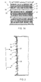
- FIG. 1 shows a metal (e.g. steel) cylindrical screen cylinder 10, with first and second metal (e.g. steel) reinforcing rings 12 and 14, respectively, on its outlet side.
- the screen cylinder 10 has three separate groove areas 16 containing rows of grooves, with several axially extending parallel grooves 18 disposed along the circumference of the screen cylinder 10.
- the grooved areas 16 are separated from each other axially by substantially cylindrical first (relatively large) land portions 20.
- Each individual groove 18 is separated from adjacent grooves 18 by substantially oblong second (relatively small) land portions 22 parallel with the grooves 18.
- Reinforcing rings 12 may be welded in a conventional manner to the land portions 20 between groove areas, or according to the present invention e.g. by laser welding. Rings 14 are welded according to the present invention to the oblong, second, small land portions 22 in the grooved areas 16. The rings 12, 14 are welded one after the other (preferably in sequence) onto the cylinder 10. Each ring 12, 14 is heated for a light shrink fit, slipped over the cylinder, placed in its proper position and fastened preferably by welding, e.g. laser spot welding, before the next ring 12, 14 is slipped over the cylinder and fastened by welding.
- the screen cylinder illustrated in FIG. 1 is a conventional out-flow screen cylinder, which is the most common type.
- the invention can be utilized with in-flow screen cylinders equally well.
- the reinforcing rings 12, 14 would be slid into the interior of the screen cylinder, the inner surface thereof then being the outlet side, and properly positioned for fastening.
- each or some of the rings 12, 14 may be partially formed, and looped around the outer surface of the screen cylinder 10, the free ends of the partially formed ring being brought together and fastened in place (typically by welding) while the ring is traversing the land areas to which it is to be welded.
- FIGURE 1B shows a screen cylinder 10 according to the invention schematically in a conventional pressure screen.
- the pressure screen is illustrated schematically by reference 11, and includes an inlet 13 for suspension (typically cellulose pulp from the pulp and paper industry at varying consistencies, typically between about 0.3 - 6 %, preferably between about 0.3 - 1.5 % for the embodiment of screen cylinder 10 illustrated in FIGS. 1 - 3) to be screened. Since the screen cylinder 10 illustrated in the drawings is an out-flow screen cylinder, the inlet 13 is to the interior of the screen cylinder 10.
- suspension typically cellulose pulp from the pulp and paper industry at varying consistencies, typically between about 0.3 - 6 %, preferably between about 0.3 - 1.5 % for the embodiment of screen cylinder 10 illustrated in FIGS. 1 - 3
- the inlet 13 is to the interior of the screen cylinder 10.
- the screen 11 also includes an outlet 15 for accepts, an outlet 17 for rejects, and a pulsing structure for causing the cellulose pulp to flow in a primarily circumferential path along the inlet side surface of the screen cylinder 10.
- the pulsing structure in this embodiment is shown as a rotor 19. However it is to be understood that any conventional pulsing structure, whether stationary (while the screen cylinder 10 is rotating) or rotating may be provided, and the rotor 19 is only one of many examples of such a pulsing structure.
- FIG. 2 which is a fragmentary elevational sectional view taken axially along a side of the screen cylinder shown in FIG. 1A, more clearly shows the grooves 18 between land portions 20 and reinforcing rings 12 and 14 welded to cylindrical land portions 20 and oblong land portions 22 respectively.
- Rings 14 provide stability increasing members connecting the land portions 22 between adjacent grooves 18. Only very small welds should be used to weld the rings 14 in their proper place.
- a continuous, non-stopping welding process i.e. a very small TIG. This prevents high temperature differences from accruing in the land portions 22 especially close to the screening slots of the grooves 18.
- the size of the "small" welds utilized according to the present invention will vary according to the size of the screen cylinder and material of which it is made, and other factors, for TIG-welding a typical small weld could vary between about 1 - 3 mm in width, preferably about 2 mm. Fusion welding (resistant-spot-welding) is more difficult to specify dimensionally.
- the weld should have a width dimension that is at least 75 % of the width of the land area 22, and typically almost the entire width of the land area 22, without overlapping to interfere with accepts flow, and typically the length of the small weld would be at least 50 % of the width of the ring 14 at the weld.
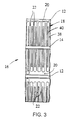
- FIG 3 shows a fragment of a groove area 16 of FIG. 2 taken at area 3-3 in FIG. 2.
- FIG. 3 shows rings 12 fastened to the cylindrical land portions 20 between rows of grooves 18 and a ring 14 bridging perpendicularly over several adjacent grooves 18 in the grooved area 16.
- the grooves 18 each typically include a relief groove 38 and a screening slot 40, (the actual sizing slot) disposed in the bottom of the relief groove 38.
- the grooves 18 and slots 40 may be made by any suitable manufacturing technique, e.g. by conventional milling, laser cutting or water jet cutting. In many screen cylinders 10 a slot 40 will be provided in all (or substantially all) of the grooves 18. However cylinders 10 may be constructed in which other openings (e.g. round or oblong holes) may be provided in at least some of the grooves 18 in place (or in addition to) the slots 40.
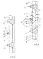
- FIG. 4 shows in an enlarged portion of the sectional view of the screen cylinder shown in FIG. 2 one way of fastening a reinforcement ring 14 to a land portion 22.
- the ring 14 is welded by laser 24 welding radially through the ring 14, such that a welded seam 26 is formed between the outer surface 28 of the oblong land portion 22 and the inner cylindrical surface 30 of the ring 14.
- the welded seam 26, which is rather small (e.g. about 1 - 3 mm in width) and covered by the ring 14 does not form an obstruction outside (e.g. on the sides of) the ring 14 preventing flow of fiber suspension.
- the inner cylindrical surface of the ring 14 may have a chamfer for providing space for the weld 26, a chamfer 27 being shown in FIG. 4 greatly exaggerated in size for clarity of illustration.
- a continuous laser welded seam 26 would typically be made continuous along the whole circumference of the ring 14, i.e. also over those areas of the ring 14 bridging over grooves 18 and slots 40.
- the laser weld 26 formed is very small and does not in any noticeable way protrude (e.g. on the sides of) into the grooves 18 or cause changes in flow conditions of the suspension being screened.
- the flow of fiber suspension is not significantly adversely affected by the ring 14 or the weld 26 on its inner cylindrical surface. Accept flow passes from the inlet side of the cylinder -- as shown by arrows in FIG.
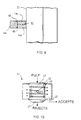
- FIG. 5 is an illustration like that of FIG. 4 but showing another preferred exemplary embodiment of the present invention.
- two rings 14a and 14b together form a composite reinforcement ring (14).
- First ring 14a is looped on the screen cylinder 10 and welded by a minor weld 32 to the oblong land portion 22.
- One side of the inner cylindrical plane of the first ring 14a is slightly bevelled -- as seen in FIG. 5 -- to provide space for the weld 32.
- a second ring 14b is looped onto the screen cylinder 10, such that the second ring 14b covers the minor weld 32.
- One side of the outer cylindrical plane of the second ring 14b is slightly bevelled -- as seen in FIG.5 -- to provide space for a second minor weld 34.
- the second minor weld 34 fastens the second ring 14b with the first ring 14a.
- the welds 32, 34 are well protected and do not protrude to either side of the composite ring 14a,
- FIG. 6 shows welding of a ring 14 having a radial extension (dimension 43) too large to be welded by radial laser welding through the ring 14.
- the ring 14 is welded from the side through one radial side plane 42, whereby a laser beam need only penetrate a short portion of the ring 14, and welding can be performed, the weld 26 being formed.
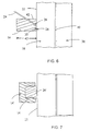
- FIG. 7 shows a small ring 14, giving only a limited structural reinforcement to the screen cylinder 10, "gently” continuously spot welded -- as indicated at 26' -- onto the cylinder 10 without heating or affecting the land portions 22 between adjacent grooves and slots.
- a second, reinforcement ring 14' is looped over the small ring 14 (before the ends of each of the rings 14, 14' are welded to each other) to ensure structural stability of the cylinder 10.
- the reinforcement ring 14' has a U-shaped radial cross section, opening inwardly toward the cylinder 10.
- the second ring 14' does not have to be welded to the actual cylinder 10 itself.
- the second ring 14' may be welded to the small ring 14 or may not need to be fastened by welding at all (i.e. the U shaped cross-section of ring 14' may keep the rings 14, 14' in place), as its cylindrical form keeps it tight around the cylinder 10.
- FIG. 8 shows still another reinforcement ring construction, comprising two small rings 14c and 14d, the ring 14c connected to the land portions 22 between grooves by a weld 32, as shown in FIG. 5.
- a reinforcement ring 14e is fastened by welding, conventional or laser welding, or electron beam or resistance welding, radially outwardly onto the two small rings 14c, 14d, i.e. by welds 45.
- the reinforcement ring 14e can be welded to the first rings 14c and 14d without affecting the land portions 22 between grooves 18 and slots 40 of the cylinder 10.
- the present invention provides a screen cylinder 10 in which, due to reinforcement rings 14, etc., welded also adjacent grooved areas, effective slot 40 length can be increased by 10 - 80 %, typically 40 - 70 %, compared to conventional screen cylinders.
- each relief groove 38 is, if made by conventional milling, about 20 mm longer than the slot 40 and a land area 22 of about 20 mm is present between rows of slots 40.
- Grooves 18 made by water-jet or laser cutting may have almost the same length on the sizing slot as the relief groove.
- the sum of the actual lengths of slots 40 in a column of grooves 18 extending axially in a straight line along the cylinder 10 divided by the effective axial length of the cylinder 10 is between about 0.65 - 0.90 (compared to about 0.45 - 0.55 in conventional screen cylinders), and preferably this ratio is greater than 0.7 to about 0.8 or about 0.9.
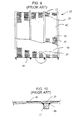
- FIG. 9 shows a typical conventional screen cylinder from the outside 42 and partly opened up from the inside 44.
- the screen cylinder 10 has 6 rows of circumferential groove areas 16, with slots 40 having a length of 50 mm.
- Each circumferential land area 20 between two neighboring rows of circumferential groove areas 16 has a considerable axial dimension.
- Total axial slot length is 300 mm.
- a ring 12 having an axial length of 22 mm is fastened by conventional welding, with welds 46, onto every second circumferential land area 20.
- the land areas 20 having, for stability reasons, an axial length of about twice the axial length of the ring 12 and about the same length as the sizing slot 40, as can be seen in the enlargement (FIG. 10) of the encircled portion of the cross section of the wall 45 of the screen cylinder 10 in FIG. 9.
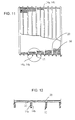
- FIGS. 11 and 12 show a view corresponding to the view on FIGS. 9 and 10 of a screen cylinder according to the present invention, the cylinder having only 5 rows of circumferential groove areas 16, with circumferential land areas 20 there between.
- a composite double ring construction 14a, 14b similar to the ring construction shown in FIG. 5, is welded according to the present invention onto each land area 20 and also onto each groove area 16 approximately in the middle between each circumferential land area 20.
- the rings 12 in this embodiment have the same size and construction as the ring 14 (i.e. with parts like 14a, 14b). These latter rings are fastened by laser, electron beam or resistance welding onto the land portions 22 between two neighboring grooves 18.
- a total of 9 rings are welded onto the cylinder 10 of FIG. 11, which allows the composite rings 14a, 14b to each be much smaller than each of the two rings 12 used in conventional screen cylinder shown in FIGS. 9 and 10.
- the circumferential land areas 22 have a very small axial dimension compared to the lengths of the grooves 18 and slots 40, as can be seen in FIG. 12.
- the slots 40 have a length of 85 mm, providing a total axial slot length of 425 mm. This leads to an approx. 42 % bigger open area compared to conventional screen cylinders, such as shown in FIG. 9.
- reinforcement rings can be fastened on screen cylinders in a gentle manner, with several gentle welds without negatively affecting the screen construction, i.e. the screening or flow conditions in the screen.
- Normally rings 14 should be welded to substantially all land areas 22 they traverse, but in some circumstances they may be welded to only some of the land areas 22 (but normally at least a majority).
- the embodiments described above are best suited for use in screening pulps in the lower consistency range, e.g. between about 0.3 - 1.5 %, and high flow volumes where highly aggressive (high power) rotors actions are not required.
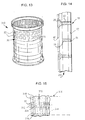
- HOwever where the pulp consistency is between about 1.5 - 6.0 %, or otherwise where aggressive rotors are used (that is where the power consumption is above about 30 kW/m 2 of cylinder surface area) instead of -- or preferably in addition to -- the rings 12, 14 described above a metal (e.g. steel) backing support cylinder with large (typically square) punched openings can also be provided, e.g. attached to the rings, e.g. by welding. Such an embodiment is illustrated in FIGS. 13 and 14.
- the screen cylinder 210 has a punched metal (e.g. steel) cylinder 50 which is looped around the rings 12, 14 and is welded, or otherwise attached, thereto.
- the metal body 51 of the cylinder 50 has a number of large (i.e. at least three times as width as a groove 18, and typically about 5 - 15 times as wide) openings 52 punched therein, the openings 52 preferably having a square configuration as illustrated in FIG. 13.
- the cylinder 50 may be looped over the surface of the cylinder 210 itself, and welded at the land areas 20 and/or 22.
- the circumferential solid land areas (20) are interrupted by grooves (with slots) which bridge them, and are staggered between the normal rows of grooves and slots.
- the first and second rings used are essentially the same as in the conventional constructions, and have substantially the same spacings between them, the first rings merely have the welds thereof interrupted by the staggered, bridging, grooves.
- FIG. 15 Such an embodiment is seen schematically in FIG. 15.
- elements are shown by the same reference numerals as in FIGS. 1 - 3 embodiments, only preceded by a "3".
- the cylinder 310 surface has, in addition to the grooves 318 (with slots therein, not shown in FIG.
- grooves 55 (with slots therein) which bridge the otherwise circumferential land areas 320, the grooves 55 staggered with respect to the grooves 318.
- the rings 312, 314 are welded to the land areas 320, 322, and are spaced from each other in substantially the same way, and with the same spacing between them, as are the rings 12, 14 in the FIGS. 1 - 3 embodiment.
- the very small welding has to be made preferably with laser, electron beam or TIG, with an absolute minimum of energy at which heat effect for welding still can be attained to prevent stresses caused by shrinkage.
Landscapes
- Engineering & Computer Science (AREA)
- Mechanical Engineering (AREA)
- Paper (AREA)
- Separation Using Semi-Permeable Membranes (AREA)
- Separation Of Solids By Using Liquids Or Pneumatic Power (AREA)
Applications Claiming Priority (3)
| Application Number | Priority Date | Filing Date | Title |
|---|---|---|---|
| US451349 | 1995-05-26 | ||
| US08/451,349 US5718826A (en) | 1995-05-26 | 1995-05-26 | Screen and method of manufacture |
| PCT/FI1996/000296 WO1996037655A1 (en) | 1995-05-26 | 1996-05-24 | Screen and method of manufacture |
Publications (2)
| Publication Number | Publication Date |
|---|---|
| EP0839227A1 EP0839227A1 (en) | 1998-05-06 |
| EP0839227B1 true EP0839227B1 (en) | 2000-05-03 |
Family
ID=23791852
Family Applications (1)
| Application Number | Title | Priority Date | Filing Date |
|---|---|---|---|
| EP96919817A Revoked EP0839227B1 (en) | 1995-05-26 | 1996-05-24 | Screen and method of manufacture |
Country Status (8)
| Country | Link |
|---|---|
| US (2) | US5718826A (ko) |
| EP (1) | EP0839227B1 (ko) |
| JP (1) | JPH11505889A (ko) |
| KR (1) | KR100246530B1 (ko) |
| CA (1) | CA2221273C (ko) |
| DE (1) | DE69608109T2 (ko) |
| TW (1) | TW315308B (ko) |
| WO (1) | WO1996037655A1 (ko) |
Families Citing this family (31)
| Publication number | Priority date | Publication date | Assignee | Title |
|---|---|---|---|---|
| US5200072A (en) | 1990-08-16 | 1993-04-06 | Ahlstrom Screen Plates Inc. | Screen plates and methods of manufacture |
| US5954956A (en) * | 1997-07-22 | 1999-09-21 | J&L Fiber Services | Modular screen cylinder and a method for its manufacture |
| FI103208B (fi) * | 1997-10-29 | 1999-05-14 | Valmet Corp | Menetelmä sihtisylinterin valmistamiseksi sekä sihtisylinteri |
| SE515006C2 (sv) * | 1998-01-29 | 2001-05-28 | Gl & V Celleco Ab | Cylindrisk sil och sätt att framställa en cylindrisk sil med utformade utsprång |
| DE19804493B4 (de) * | 1998-02-05 | 2008-03-27 | Pall Corp. | Filtermedium für die Fest/Flüssig-Trennung |
| US6138838A (en) | 1998-05-29 | 2000-10-31 | J&L Fiber Services, Inc. | Screen media and a screening passage therefore |
| US6120033A (en) * | 1998-06-17 | 2000-09-19 | Rosemount Inc. | Process diaphragm seal |
| US6324490B1 (en) * | 1999-01-25 | 2001-11-27 | J&L Fiber Services, Inc. | Monitoring system and method for a fiber processing apparatus |
| WO2000064600A1 (en) * | 1999-04-28 | 2000-11-02 | Thermo Black Clawson Inc. | Improved torque transmission for slotted screen cylinders |
| US6491168B1 (en) | 2000-04-23 | 2002-12-10 | J + L Fiber Services, Inc. | Pulp screen basket |
| FR2809029B1 (fr) * | 2000-05-16 | 2002-06-21 | Johnson Filtration Systems | Procede de fabrication d'un panier mecanique de filtration |
| US6460757B1 (en) | 2000-11-14 | 2002-10-08 | Newscreen As | Apparatus and method for forming slotted wire screens |
| WO2002083263A1 (en) * | 2001-04-16 | 2002-10-24 | J & L Fiber Services, Inc. | Screen cylinder and method |
| SE518956C2 (sv) * | 2001-05-11 | 2002-12-10 | Metso Paper Inc | Silanordning för separering av en fibersuspension |
| SE519079C2 (sv) * | 2001-05-30 | 2003-01-07 | Metso Paper Inc | Sil för silning av massasuspensioner innefattande en stödring med konisk yta |
| FI119440B (fi) * | 2004-07-16 | 2008-11-14 | Advanced Fiber Tech Aft Trust | Menetelmä seulasylinterin valmistamiseksi ja seulasylinteri |
| US20060027492A1 (en) * | 2004-08-06 | 2006-02-09 | Lin Mao C | Filter mechanism |
| CA2609881C (en) * | 2005-05-09 | 2012-05-29 | Marc-Andre Hetu | Screen basket with replaceable profiled bars |
| BRPI0819362B1 (pt) * | 2007-11-14 | 2018-12-26 | Filtration Fibrewall Inc | cesta-peneira |
| US20090211965A1 (en) * | 2008-02-21 | 2009-08-27 | Weatherford/Lamb, Inc. | Arrangement for splicing panels together to form a cylindrical screen |
| EP2324154A2 (de) * | 2008-08-11 | 2011-05-25 | Voith Patent GmbH | Anordnung zur fraktionierung einer faserstoffsuspension |
| US8028691B2 (en) | 2008-10-27 | 2011-10-04 | Johnson Screens, Inc. | Passive solar wire screens for buildings |
| US9303493B2 (en) | 2009-05-15 | 2016-04-05 | Vast Power Portfolio, Llc | Method and apparatus for strain relief in thermal liners for fluid transfer |
| RU2012154307A (ru) | 2010-05-17 | 2014-06-27 | Васт Пауэр Портфоулиоу, Ллк | Сгибаемый хвостовик с компенсацией деформации для фильтрации текучих сред, способ и устройство |
| US9023456B2 (en) | 2011-03-18 | 2015-05-05 | Bilfinger Water Technologies, Inc. | Profiled wire screen for process flow and other applications |
| CN103643581B (zh) * | 2013-12-31 | 2016-03-02 | 山东晨钟机械股份有限公司 | 精筛 |
| DE102015003020B3 (de) * | 2015-03-06 | 2016-03-03 | Andritz Fiedler Gmbh | Stabsiebkorb |
| CN108114892A (zh) * | 2016-11-28 | 2018-06-05 | 长圆工业股份有限公司 | 可螺旋定位筛条的高效节能筛网 |
| CN107498179A (zh) * | 2017-09-27 | 2017-12-22 | 杨沁玥 | 一种滤网焊接工艺 |
| CN107378247A (zh) * | 2017-09-27 | 2017-11-24 | 杨沁玥 | 一种滤网激光叠焊工艺 |
| CN112090719A (zh) * | 2020-09-08 | 2020-12-18 | 邵双林 | 一种用于荔枝干多级筛选设备 |
Family Cites Families (15)
| Publication number | Priority date | Publication date | Assignee | Title |
|---|---|---|---|---|
| US273836A (en) * | 1883-03-13 | Flour-bolt | ||
| SE72627C1 (ko) * | ||||
| US1948606A (en) * | 1931-01-12 | 1934-02-27 | Arthur J Weinig | Separating apparatus |
| US1933154A (en) * | 1932-08-25 | 1933-10-31 | John A Spencer | Dandy roll construction |
| US3631981A (en) * | 1969-02-06 | 1972-01-04 | Ingersoll Rand Canada | Blotted pulp screen |
| US4127478A (en) * | 1977-03-04 | 1978-11-28 | Hy-Way Heat Systems, Inc. | Machine for salvaging waste concrete material |
| US4410424A (en) * | 1980-05-02 | 1983-10-18 | The Black Clawson Company | Screening apparatus for paper making stock |
| US5064537A (en) * | 1987-04-16 | 1991-11-12 | The Black Clawson Company | Seamless screen cylinder with laser cut openings |
| US5200072A (en) * | 1990-08-16 | 1993-04-06 | Ahlstrom Screen Plates Inc. | Screen plates and methods of manufacture |
| FR2675520A1 (fr) * | 1991-04-17 | 1992-10-23 | Lamort Em | Tamis pour epurateur et classificateur de pate a papier et son procede de realisation. |
| SE9102550L (sv) * | 1991-09-05 | 1993-03-06 | Sunds Defibrator Ind Ab | Saett foer framstaellning av en siltrumma |
| US5513757A (en) * | 1994-06-02 | 1996-05-07 | Sulzer Papertec Mansfield Inc. | Continuous cut slotted screen basket |
| US5823355A (en) * | 1995-03-29 | 1998-10-20 | Beloit Technologies, Inc. | Fibresaver screen basket support |
| US5618424A (en) * | 1995-04-21 | 1997-04-08 | Nagaoka International Corp. | Rotary drum type device for separating solid particles from a liquid |
| US5954956A (en) * | 1997-07-22 | 1999-09-21 | J&L Fiber Services | Modular screen cylinder and a method for its manufacture |
-
1995
- 1995-05-26 US US08/451,349 patent/US5718826A/en not_active Expired - Lifetime
-
1996
- 1996-05-24 EP EP96919817A patent/EP0839227B1/en not_active Revoked
- 1996-05-24 JP JP8535428A patent/JPH11505889A/ja active Pending
- 1996-05-24 CA CA002221273A patent/CA2221273C/en not_active Expired - Fee Related
- 1996-05-24 KR KR1019970708506A patent/KR100246530B1/ko not_active IP Right Cessation
- 1996-05-24 WO PCT/FI1996/000296 patent/WO1996037655A1/en active IP Right Grant
- 1996-05-24 DE DE69608109T patent/DE69608109T2/de not_active Expired - Lifetime
- 1996-06-01 TW TW085106557A patent/TW315308B/zh active
-
1998
- 1998-01-12 US US09/013,167 patent/US6021905A/en not_active Expired - Lifetime
Also Published As
| Publication number | Publication date |
|---|---|
| CA2221273A1 (en) | 1996-11-28 |
| US5718826A (en) | 1998-02-17 |
| TW315308B (ko) | 1997-09-11 |
| US6021905A (en) | 2000-02-08 |
| WO1996037655A1 (en) | 1996-11-28 |
| CA2221273C (en) | 2000-04-18 |
| EP0839227A1 (en) | 1998-05-06 |
| DE69608109T2 (de) | 2001-01-11 |
| DE69608109D1 (de) | 2000-06-08 |
| JPH11505889A (ja) | 1999-05-25 |
| KR100246530B1 (ko) | 2000-03-15 |
| KR19990022027A (ko) | 1999-03-25 |
Similar Documents
| Publication | Publication Date | Title |
|---|---|---|
| EP0839227B1 (en) | Screen and method of manufacture | |
| USRE39940E1 (en) | Screen plates and methods of manufacture | |
| EP0287267B1 (en) | Cylindrical screen plates | |
| US6426003B2 (en) | Screening device and method of manufacture | |
| US4885090A (en) | Screen plates | |
| US7188733B2 (en) | Screening device, such as a screen cylinder, and method of manufacture of the screening device | |
| US5513757A (en) | Continuous cut slotted screen basket | |
| FI100010B (fi) | Seulasylinteri | |
| EP0842322B1 (en) | Multiple contour screening | |
| EP0958432B1 (en) | A wire screen product | |
| US4901417A (en) | Method of finishing screen plates | |
| WO2000025889A1 (en) | Reinforcement of conventional wedge wire screens | |
| WO2021032910A1 (en) | A screen cylinder | |
| CA2178683A1 (en) | A cylindric screen basket and a method of making same | |
| EP1073787A1 (en) | A cylindrical screen and a method of manufacturing it | |
| WO1995005248A1 (en) | Slotted screen for paper stock | |
| MXPA00008271A (es) | Cilindro de filtro con alto porcentaje de area cubierta |
Legal Events
| Date | Code | Title | Description |
|---|---|---|---|
| PUAI | Public reference made under article 153(3) epc to a published international application that has entered the european phase |
Free format text: ORIGINAL CODE: 0009012 |
|
| 17P | Request for examination filed |
Effective date: 19971202 |
|
| AK | Designated contracting states |
Kind code of ref document: A1 Designated state(s): DE FI FR IT SE |
|
| 17Q | First examination report despatched |
Effective date: 19981127 |
|
| GRAG | Despatch of communication of intention to grant |
Free format text: ORIGINAL CODE: EPIDOS AGRA |
|
| GRAG | Despatch of communication of intention to grant |
Free format text: ORIGINAL CODE: EPIDOS AGRA |
|
| GRAG | Despatch of communication of intention to grant |
Free format text: ORIGINAL CODE: EPIDOS AGRA |
|
| GRAH | Despatch of communication of intention to grant a patent |
Free format text: ORIGINAL CODE: EPIDOS IGRA |
|
| GRAH | Despatch of communication of intention to grant a patent |
Free format text: ORIGINAL CODE: EPIDOS IGRA |
|
| GRAA | (expected) grant |
Free format text: ORIGINAL CODE: 0009210 |
|
| AK | Designated contracting states |
Kind code of ref document: B1 Designated state(s): DE FI FR IT SE |
|
| REF | Corresponds to: |
Ref document number: 69608109 Country of ref document: DE Date of ref document: 20000608 |
|
| ITF | It: translation for a ep patent filed |
Owner name: JACOBACCI & PERANI S.P.A. |
|
| ET | Fr: translation filed | ||
| PLAV | Examination of admissibility of opposition |
Free format text: ORIGINAL CODE: EPIDOS OPEX |
|
| PLBQ | Unpublished change to opponent data |
Free format text: ORIGINAL CODE: EPIDOS OPPO |
|
| PLBI | Opposition filed |
Free format text: ORIGINAL CODE: 0009260 |
|
| 26 | Opposition filed |
Opponent name: HEINRICH FIEDLER GMBH & CO. KG Effective date: 20010202 |
|
| PLAV | Examination of admissibility of opposition |
Free format text: ORIGINAL CODE: EPIDOS OPEX |
|
| PLBF | Reply of patent proprietor to notice(s) of opposition |
Free format text: ORIGINAL CODE: EPIDOS OBSO |
|
| PLBF | Reply of patent proprietor to notice(s) of opposition |
Free format text: ORIGINAL CODE: EPIDOS OBSO |
|
| PLBF | Reply of patent proprietor to notice(s) of opposition |
Free format text: ORIGINAL CODE: EPIDOS OBSO |
|
| RAP2 | Party data changed (patent owner data changed or rights of a patent transferred) |
Owner name: ADVANCED FIBER TECHNOLOGIES (AFT) OY |
|
| REG | Reference to a national code |
Ref country code: FR Ref legal event code: TP |
|
| PLAB | Opposition data, opponent's data or that of the opponent's representative modified |
Free format text: ORIGINAL CODE: 0009299OPPO |
|
| R26 | Opposition filed (corrected) |
Opponent name: ANDRITZ FIEDLER GMBH & CO. Effective date: 20010202 |
|
| PLAY | Examination report in opposition despatched + time limit |
Free format text: ORIGINAL CODE: EPIDOSNORE2 |
|
| PLBC | Reply to examination report in opposition received |
Free format text: ORIGINAL CODE: EPIDOSNORE3 |
|
| PGFP | Annual fee paid to national office [announced via postgrant information from national office to epo] |
Ref country code: SE Payment date: 20090514 Year of fee payment: 14 Ref country code: IT Payment date: 20090528 Year of fee payment: 14 Ref country code: FR Payment date: 20090513 Year of fee payment: 14 Ref country code: FI Payment date: 20090515 Year of fee payment: 14 |
|
| PG25 | Lapsed in a contracting state [announced via postgrant information from national office to epo] |
Ref country code: FI Free format text: LAPSE BECAUSE OF NON-PAYMENT OF DUE FEES Effective date: 20100524 |
|
| EUG | Se: european patent has lapsed | ||
| REG | Reference to a national code |
Ref country code: FR Ref legal event code: ST Effective date: 20110131 |
|
| PG25 | Lapsed in a contracting state [announced via postgrant information from national office to epo] |
Ref country code: IT Free format text: LAPSE BECAUSE OF NON-PAYMENT OF DUE FEES Effective date: 20100524 Ref country code: SE Free format text: LAPSE BECAUSE OF NON-PAYMENT OF DUE FEES Effective date: 20100525 |
|
| PG25 | Lapsed in a contracting state [announced via postgrant information from national office to epo] |
Ref country code: FR Free format text: LAPSE BECAUSE OF NON-PAYMENT OF DUE FEES Effective date: 20100531 |
|
| PLAY | Examination report in opposition despatched + time limit |
Free format text: ORIGINAL CODE: EPIDOSNORE2 |
|
| PLAH | Information related to despatch of examination report in opposition + time limit modified |
Free format text: ORIGINAL CODE: EPIDOSCORE2 |
|
| PLBC | Reply to examination report in opposition received |
Free format text: ORIGINAL CODE: EPIDOSNORE3 |
|
| PGFP | Annual fee paid to national office [announced via postgrant information from national office to epo] |
Ref country code: DE Payment date: 20140521 Year of fee payment: 19 |
|
| PLAY | Examination report in opposition despatched + time limit |
Free format text: ORIGINAL CODE: EPIDOSNORE2 |
|
| PLBC | Reply to examination report in opposition received |
Free format text: ORIGINAL CODE: EPIDOSNORE3 |
|
| REG | Reference to a national code |
Ref country code: DE Ref legal event code: R119 Ref document number: 69608109 Country of ref document: DE |
|
| RDAF | Communication despatched that patent is revoked |
Free format text: ORIGINAL CODE: EPIDOSNREV1 |
|
| RDAG | Patent revoked |
Free format text: ORIGINAL CODE: 0009271 |
|
| STAA | Information on the status of an ep patent application or granted ep patent |
Free format text: STATUS: PATENT REVOKED |
|
| 27W | Patent revoked |
Effective date: 20151214 |
|
| PG25 | Lapsed in a contracting state [announced via postgrant information from national office to epo] |
Ref country code: DE Free format text: LAPSE BECAUSE OF NON-PAYMENT OF DUE FEES Effective date: 20151201 |
|
| REG | Reference to a national code |
Ref country code: SE Ref legal event code: ECNC |