EP0837032A1 - Générateur d' ozone - Google Patents
Générateur d' ozone Download PDFInfo
- Publication number
- EP0837032A1 EP0837032A1 EP97308122A EP97308122A EP0837032A1 EP 0837032 A1 EP0837032 A1 EP 0837032A1 EP 97308122 A EP97308122 A EP 97308122A EP 97308122 A EP97308122 A EP 97308122A EP 0837032 A1 EP0837032 A1 EP 0837032A1
- Authority
- EP
- European Patent Office
- Prior art keywords
- electrode
- ozone generator
- ozone
- layer
- generator according
- Prior art date
- Legal status (The legal status is an assumption and is not a legal conclusion. Google has not performed a legal analysis and makes no representation as to the accuracy of the status listed.)
- Withdrawn
Links
Images

Classifications
-
- C—CHEMISTRY; METALLURGY
- C01—INORGANIC CHEMISTRY
- C01B—NON-METALLIC ELEMENTS; COMPOUNDS THEREOF; METALLOIDS OR COMPOUNDS THEREOF NOT COVERED BY SUBCLASS C01C
- C01B13/00—Oxygen; Ozone; Oxides or hydroxides in general
- C01B13/10—Preparation of ozone
- C01B13/11—Preparation of ozone by electric discharge
-
- C—CHEMISTRY; METALLURGY
- C01—INORGANIC CHEMISTRY
- C01B—NON-METALLIC ELEMENTS; COMPOUNDS THEREOF; METALLOIDS OR COMPOUNDS THEREOF NOT COVERED BY SUBCLASS C01C
- C01B2201/00—Preparation of ozone by electrical discharge
- C01B2201/20—Electrodes used for obtaining electrical discharge
- C01B2201/22—Constructional details of the electrodes
-
- C—CHEMISTRY; METALLURGY
- C01—INORGANIC CHEMISTRY
- C01B—NON-METALLIC ELEMENTS; COMPOUNDS THEREOF; METALLOIDS OR COMPOUNDS THEREOF NOT COVERED BY SUBCLASS C01C
- C01B2201/00—Preparation of ozone by electrical discharge
- C01B2201/20—Electrodes used for obtaining electrical discharge
- C01B2201/24—Composition of the electrodes
Definitions
- This invention relates to an ozone generator for the production of ozone.
- Ozone also referred to as "activated oxygen”
- activate oxygen is an allotropic form of oxygen, and is the fourth strongest oxidant. It has the formula O 3 , and is formed by the action of ultraviolet light on oxygen.
- the reaction is endothermic.
- Ozone is an effective disinfecting and deodorising agent.
- Ozone is capable of killing bacteria by breaking up their molecular structure. Thus, where unpleasant or harmful smells are caused by noxious airborne chemicals and by surface bacteria, the ozone kills the bacteria and breaks down the molecular structures of the chemicals, thus disinfecting and deodorising. Even at a low level of 0.1 part per million, ozone is an effective bactericide. Because ozone is unstable, the ozone decomposes to oxygen leaving no residues to further eliminate. Ozone can also be used to sterilise water by dissolving ozone in it.
- the process of ozonising i.e. treating with ozone has many applications, for example, in the sterilising of work surfaces in kitchens, for disinfecting and deodorising public conveniences, and, when dissolved, for sterilising swimming pools instead of using chlorine.
- a known ozone generator - or ozoniser as they are commonly referred to as - comprises a generating cell, the generating cell comprising a glass tube provided with an inner aluminium coating and concentrically mounted within a stainless steel tube. Spacers are used to ensure a uniform gap between the glass tube and the stainless steel tube.
- the aluminium coating is coupled to a high voltage supply and the stainless steel tube is coupled to earth.
- the stainless steel tube forms a first electrode, the aluminium coating a second electrode, the two being separated by a dielectric - the glass, and an air gap.
- An oxygen containing gas is passed along the gap, and the high voltage alternating current applied across the electrodes, thus producing some ozone molecules from the oxygen molecules in the gas by silent electrical discharge.
- Excess energy ie: energy from the electrical voltage not utilised in the reactions to form ozone
- the generating cell is surrounded by a water - cooled jacket to prevent overheating.
- Another known ozoniser uses a generating cell comprising a glass or ceramic tube with an inner silver mirror coating and an outer stainless steel mesh.
- the mirrored coating has poor adhesion to the substrate and is likely to wear off over time.
- Ceramics have been used as the dielectric, but when they are used, the dimensions of the air gap become extremely critical to provide efficient and satisfactory ozone production otherwise the silent electrical discharge will only result on one side of the tube. It is extremely difficult to manufacture ceramics to the tolerances required.
- an ozone generator comprising at least one ozonising element, said at least one ozonising element comprising a first electrode, a second electrode and means for coupling a high-tension voltage there between, each ozonising element being operable to produce ozone when the high-tension voltage is applied across the first and second electrodes in the presence of an oxygen supply, characterised in that the first electrode comprises a layer of conductive material provided on one side of a dielectric substrate, and the second electrode comprises a layer of conductive material on the reverse side of the substrate.
- the first electrode may comprise a layer of titanium provided on a ceramic substrate, and the second electrode may be a layer of conducting ink on the reverse side of the substrate, such as a metallic ink such as gold ink.
- the titanium layer may be formed using a plasma spraying technique using titanium powder.
- the generating means may include more than one front and back electrode. This ozone generating means has the advantage of being cheap and easy to manufacture and modular in concept. Because the front, Titanium, electrode is a metallic layer, the arrangement is electrostatically less noisy than known ozone generating devices, which means that the generator of the present invention is more electromagnetically compatible than known devices. A sprayed metallic layer is less prone to damage - especially during manufacture - which lends itself to large scale production.
- the electrodes are also less prone to corrosion in the chemically aggressive environment of ozone production.
- the ozonising element comprising the front and back electrodes and dielectric substrate may be removable for cleaning, and because the front and back electrodes are formed as layers on the dielectric substrate, it withstands cleaning well.
- An ozone generating cell may be provided with a heat sink.
- the heat sink comprises at least one aluminium block.
- Said heat sink may comprise an array of cooling fins.
- the heat sink is bonded to the ozone generating cell by a heat conducting resin or adhesive.
- the second electrode may comprise an electrically conductive resin or adhesive.
- a generating cell 1 comprises one or more elements 8 each element 8 comprising a front electrode 2 deposited on a substrate 3.
- a back electrode 4 On the reverse side of the substrate 3 there is provided a back electrode 4.
- the front electrode 2 comprises a "finger" of Titanium formed as a layer of sprayed Titanium powder as discussed in more detail below.
- the back electrode 4 is a layer of a conducting ink, for example, Heraeus C4081.
- a high tension voltage supply V can be coupled across the front and back electrodes 2,4 by means of contact regions 5, 6.
- the front contact region 6 comprises a strip of conducting ink adjacent one end of the substrate 3 contacting the front electrode 2.
- the back contact region 5 also comprises a strip of conducting ink provided adjacent the other end of the substrate 3 on the reverse side contacting the back electrode 4 to form - with the back electrode 4 - a T-shaped region of conducting ink as illustrated in Figure 2.
- the back electrode 4 and the contact regions 5, 6 are deposited using silk screen techniques.
- ozone is generated in the vicinity of the titanium fingers.
- an oxygen-containing gas for example, air
- a high-tension voltage V across the two electrodes 2,4
- an ozone output of approximately 50mg per hour can be achieved.
- a back electrode would, typically, be approximately 40mm long by 4 mm wide.
- the high-tension voltage V is coupled across the front and back electrodes by coupling the high tension supply V to the contact regions 5,6 using connecting wires 14,15 soldered to the contact regions 5,6.
- metallic spring clips can be used to contact the contact regions 5,6.
- the element 17 comprising the ceramic substrate 3 with the front and back electrodes thereon to be removed for cleaning.
- the element 17 is cleaned by wiping it with a soft material impregnated with a solvent, for example, a cotton wool bud soaked in alcohol.
- each front electrode 2 must be separated by a sufficient distance to ensure that ozone is formed when the high-tension voltage is applied. If they are too close, then no ozone will be formed. This separation has to be decided empirically, but, it has been found, typically, that a minimum separation is around 5mm.
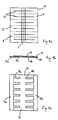
- An ozone generating cell 1 is made using alumina tiles 10, typically 10cm by 9cm in size, and 0.5 mm in thickness.
- alumina tiles 10 typically 10cm by 9cm in size, and 0.5 mm in thickness.
- six pairs of back electrodes 4a, 4b, and respective contact regibns 5a, 5b are formed on one face 13 - the reverse side as described above - of the alumina tile 10 as illustrated in Figure 4c.
- a central region of conducting ink 11 is formed on the upper side 12 which will form the contact region 6 for the front electrode 2.
- ten of the tiles 10 are placed on a backing plate (not shown) in a 5 by 2 array.
- a suitable mask is applied to the upper side 12 of the tiles 10 to obtain a pattern of six 1mm by 80mm titanium fingers 16 on each tile.
- the titanium fingers 16 are formed using a plasma spraying technique, using Titanium powder comprising particles of irregular shape and size, typically between 5 and 25 microns in diameter.
- Plasma spraying is a known technique for depositing materials on a substrate.
- a plasma torch is used in which an electric arc is contained within a constricted nozzle.
- An inert gas is passed through the nozzle and the arc, which then becomes dissociated and partially ionised, thereby increasing the gas temperature.
- a secondary gas can be added for further control.
- a powdered material is then injected into the gas stream whereby the powder particles are melted and accelerated towards the substrate such that they strike the surface of the substrate, flatten and cool. As they cool, the particles contract and bond to the roughened surface of the substrate.
- a 6mm Argon nozzle is used with Argon as the primary gas and Hydrogen as the secondary gas.
- An arc current of 500 Amps is used and an injector diameter of 1.8mm.
- a ring shroud of Argon is used with a pressure of approximately 60 psi. The deposition is carried out at a working distance of 110mm.
- a robot arm holds the plasma torch and sweeps over the tiles 10 in a series of passes until the required thickness is obtained, which is typically 50 microns.
- Each alumina tile 10 is scored with 5 substantially equidistantly spaced horizontal lines and one substantially centrally located vertical line as illustrated in Figure 4a by the dotted lines.
- the tile 10 can then be broken up into either 12 single elements 8, or generating cells comprising multiple elements up to a maximum of 12 elements per tile 10. These generating cells can be used in ozone generators to generate ozone.
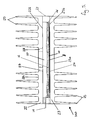
- a heat sink 22,23 is provided for an ozone generating cell 100.
- This embodiment allows the dissipation of heat from the cell 100, preventing overheating.
- the ozone generating cell 100 which in this embodiment comprises multiple elements 8, but may equally comprise a single element 8 in alternative embodiments, is made as described above.
- the ozone generating cell 100 comprises a hollow chamber 20, formed within a circumferential silicone rubber gasket 21 having four side walls.
- the gasket 21 is made of any suitable non-conducting material.
- the gasket 21 is sandwiched between upper and lower aluminium blocks 22, 23, internal surfaces 22b, 23b of which enclose the hollow chamber 20.
- the upper and lower aluminium blocks 22, 23 are solid, and each comprise an array of parallel cooling fins 25 extending from their external surfaces 22a, 23a at approximately 90 degrees to the plane of each aluminium block 22, 23.
- the aluminium blocks 22, 23 constitute upper and lower heat sinks, functioning to allow dissipation of heat from the ozone generating cell 100 to the outside.
- the ozone generating element 8 is arranged within the chamber 20 such that the lower side 13 of the alumina tile 10 of the ozone generating cell 100 is affixed to the internal surface 23b of the lower aluminium block 23 by means of an epoxy adhesive layer 24 therebetween.
- a silicon sealant 26 around the circumference of the alumina tile 10 is also provided to prevent oxidation of the contacts of the electrodes.
- the remainder of the interior of the hollow chamber 20 is filled with air or an oxygen-containing gas mixture, or pure oxygen.
- the upper side 12 of the alumina tile 10 which carries the front electrodes 16, is therefore in contact with the oxygen, allowing the formation of ozone.
- An exit is provided in the silicon gasket 21, through which the high tension supply wire 14 connecting to the front electrodes 16 passes.
- the epoxy adhesive 24 is electrically conductive, and thus, together with the lower aluminium block 23 with which it is in contact, provides an electrical earthing means for the back electrodes 4a, 4b. It is to be noted that in an alternative embodiment, the epoxy adhesive layer 24 replaces the back electrodes 4a, 4b altogether, although in the present embodiment the back electrodes 4a, 4b are present, and comprise metallic conducting ink, such as gold ink, as previously described.
- a gas inlet 27 and a gas outlet 28 are also provided, each comprising an aperture in the upper aluminium layer 22, leading through into the chamber 20.
- one or both of these apertures are provided through the lower aluminium layer, and in a further embodiment, one or both of these apertures are provided through the silicone gasket 21.
- the gas inlet allows air into the chamber, providing the oxygen supply for the production of ozone, and the gas outlet allows the produced ozone out of the chamber.
- excess energy from the voltage (ie: energy that is not used in the reaction to produce ozone), is dissipated as heat, which is conducted to the aluminium layers 22, 23.
- the epoxy adhesive 24 is thermally conductive, and being in direct contact with the back electrodes of the ozone generating cell with no air gap, is extremely efficient at conducting heat from this area directly to the lower aluminium layer 23. Heat from the gas in the chamber is transferred into the upper aluminium layer 22.
- the cooling fins 25 increase the surface area of the aluminium layers 22, 23, and the aluminium layers 22, 23 thus act as a heat sink, dispersing heat to the outside by convection. In this way, overheating of the cell is prevented and the durability and working life of the cell increased dramatically.
- Chromium, Niobium or Zirconium for example, can be used instead of Titanium, and other materials can be used for the back electrodes and for the substrate.
- Other suitable deposition techniques could also be used.
Landscapes
- Chemical & Material Sciences (AREA)
- Organic Chemistry (AREA)
- Inorganic Chemistry (AREA)
- Oxygen, Ozone, And Oxides In General (AREA)
Applications Claiming Priority (2)
| Application Number | Priority Date | Filing Date | Title |
|---|---|---|---|
| GB9621663 | 1996-10-17 | ||
| GBGB9621663.5A GB9621663D0 (en) | 1996-10-17 | 1996-10-17 | An ozone generator |
Publications (1)
| Publication Number | Publication Date |
|---|---|
| EP0837032A1 true EP0837032A1 (fr) | 1998-04-22 |
Family
ID=10801585
Family Applications (1)
| Application Number | Title | Priority Date | Filing Date |
|---|---|---|---|
| EP97308122A Withdrawn EP0837032A1 (fr) | 1996-10-17 | 1997-10-14 | Générateur d' ozone |
Country Status (3)
| Country | Link |
|---|---|
| EP (1) | EP0837032A1 (fr) |
| JP (1) | JPH10182110A (fr) |
| GB (2) | GB9621663D0 (fr) |
Cited By (2)
| Publication number | Priority date | Publication date | Assignee | Title |
|---|---|---|---|---|
| EP1055639A2 (fr) * | 1999-05-28 | 2000-11-29 | Ozone Industries Limited | Générateur d'ozone |
| DE102008006256A1 (de) * | 2008-01-25 | 2009-07-30 | Innovative Sensor Technology Ist Ag | Baugruppe zur Erzeugung von Ozon |
Families Citing this family (1)
| Publication number | Priority date | Publication date | Assignee | Title |
|---|---|---|---|---|
| GB2534343A (en) * | 2014-11-11 | 2016-07-27 | Ozone Ind Ltd | Ozone generator plate |
Citations (5)
| Publication number | Priority date | Publication date | Assignee | Title |
|---|---|---|---|---|
| JPH0251401A (ja) * | 1988-08-13 | 1990-02-21 | Fuji Electric Co Ltd | 網電極オゾナイザおよびその製造方法 |
| JPH0388702A (ja) * | 1989-08-30 | 1991-04-15 | Kyocera Corp | オゾン発生用放電体 |
| JPH03108292A (ja) * | 1989-09-22 | 1991-05-08 | Noritake Co Ltd | オゾナイザ |
| JPH08133705A (ja) * | 1994-10-31 | 1996-05-28 | V M C:Kk | オゾナイザーの電極 |
| JPH08225308A (ja) * | 1995-02-22 | 1996-09-03 | Star Micronics Co Ltd | オゾン発生用放電体 |
Family Cites Families (6)
| Publication number | Priority date | Publication date | Assignee | Title |
|---|---|---|---|---|
| CH421388A (de) * | 1962-02-09 | 1966-09-30 | Holger Dr Lueder | Verfahren zur Elektro-Klimatisierung eines Raumes mit negativen Luftsauerstoff-Ionen |
| GB1227954A (fr) * | 1967-05-12 | 1971-04-15 | ||
| CA1020116A (en) * | 1971-05-07 | 1977-11-01 | Purification Sciences | Corona generator method and apparatus |
| US5272414A (en) * | 1990-05-08 | 1993-12-21 | I.T.M. Corporation | Discharge element, method of producing the same and apparatus comprising the same |
| JPH05166578A (ja) * | 1991-12-12 | 1993-07-02 | Ngk Spark Plug Co Ltd | 沿面コロナ放電素子及びその放電面生成物の除去方法 |
| US5525310A (en) * | 1995-08-02 | 1996-06-11 | Decker; R. Scott | Continuous corona discharge ozone generation device |
-
1996
- 1996-10-17 GB GBGB9621663.5A patent/GB9621663D0/en active Pending
-
1997
- 1997-10-14 GB GB9721617A patent/GB2318490A/en not_active Withdrawn
- 1997-10-14 EP EP97308122A patent/EP0837032A1/fr not_active Withdrawn
- 1997-10-17 JP JP28540297A patent/JPH10182110A/ja active Pending
Patent Citations (5)
| Publication number | Priority date | Publication date | Assignee | Title |
|---|---|---|---|---|
| JPH0251401A (ja) * | 1988-08-13 | 1990-02-21 | Fuji Electric Co Ltd | 網電極オゾナイザおよびその製造方法 |
| JPH0388702A (ja) * | 1989-08-30 | 1991-04-15 | Kyocera Corp | オゾン発生用放電体 |
| JPH03108292A (ja) * | 1989-09-22 | 1991-05-08 | Noritake Co Ltd | オゾナイザ |
| JPH08133705A (ja) * | 1994-10-31 | 1996-05-28 | V M C:Kk | オゾナイザーの電極 |
| JPH08225308A (ja) * | 1995-02-22 | 1996-09-03 | Star Micronics Co Ltd | オゾン発生用放電体 |
Non-Patent Citations (5)
| Title |
|---|
| PATENT ABSTRACTS OF JAPAN vol. 014, no. 215 (C - 0716) 8 May 1990 (1990-05-08) * |
| PATENT ABSTRACTS OF JAPAN vol. 015, no. 259 (C - 0846) 2 July 1991 (1991-07-02) * |
| PATENT ABSTRACTS OF JAPAN vol. 015, no. 304 (E - 1096) 5 August 1991 (1991-08-05) * |
| PATENT ABSTRACTS OF JAPAN vol. 096, no. 009 30 September 1996 (1996-09-30) * |
| PATENT ABSTRACTS OF JAPAN vol. 097, no. 001 31 January 1997 (1997-01-31) * |
Cited By (3)
| Publication number | Priority date | Publication date | Assignee | Title |
|---|---|---|---|---|
| EP1055639A2 (fr) * | 1999-05-28 | 2000-11-29 | Ozone Industries Limited | Générateur d'ozone |
| EP1055639A3 (fr) * | 1999-05-28 | 2002-06-05 | Ozone Industries Limited | Générateur d'ozone |
| DE102008006256A1 (de) * | 2008-01-25 | 2009-07-30 | Innovative Sensor Technology Ist Ag | Baugruppe zur Erzeugung von Ozon |
Also Published As
| Publication number | Publication date |
|---|---|
| GB9721617D0 (en) | 1997-12-10 |
| GB9621663D0 (en) | 1996-12-11 |
| JPH10182110A (ja) | 1998-07-07 |
| GB2318490A (en) | 1998-04-22 |
Similar Documents
| Publication | Publication Date | Title |
|---|---|---|
| US5766560A (en) | Ozone generator | |
| JP3990285B2 (ja) | 大気圧で低温プラズマを発生させる装置 | |
| US4725412A (en) | Ozone generator | |
| TW548741B (en) | Electrode for plasma processes and method for manufacture and use thereof | |
| CN1328755C (zh) | 低污染、高密度等离子蚀刻腔体及其加工方法 | |
| KR100476136B1 (ko) | 대기압 플라즈마를 이용한 표면처리장치 | |
| JP5513104B2 (ja) | プラズマ処理装置 | |
| JP2009255027A (ja) | 殺菌方法並びに殺菌装置とその装置を用いた空調機、手乾燥機及び加湿器 | |
| TW200845831A (en) | Showerhead electrode assembly with gas flow modification for extended electrode life | |
| WO2017061735A1 (fr) | Électrode de décharge à barrière diélectrique hybride utilisant de manière simultanée une décharge superficielle et une décharge spatiale | |
| KR950002576B1 (ko) | 방전소자 및 그의 응용장치 | |
| SK287455B6 (sk) | Zariadenie a spôsob čistenia, leptania, aktivácie a následné úpravy povrchu skla, povrchu skla pokrytého kysličníkmi kovov a povrchu iných materiálov pokrytých SiO2 | |
| US5272414A (en) | Discharge element, method of producing the same and apparatus comprising the same | |
| KR100466293B1 (ko) | 화학증착방법및증착장치 | |
| JP2009505342A (ja) | プラズマ発生装置及びプラズマ発生方法 | |
| EP0837032A1 (fr) | Générateur d' ozone | |
| JP2785442B2 (ja) | プラズマcvd装置 | |
| GB2148469A (en) | Steam generator | |
| US5385761A (en) | Discharge element, method of producing the same and apparatus comprising the same | |
| JP2005216763A (ja) | イオン化気流発生装置 | |
| EP1055639A2 (fr) | Générateur d'ozone | |
| KR100988291B1 (ko) | 평행 평판형 전극 구조를 구비하는 대기압 플라즈마 표면처리 장치 | |
| KR100461516B1 (ko) | 유전체 매입형 전극 보호 구조의 다단식 배리어 방전장치 | |
| JP5961899B2 (ja) | 大気圧プラズマ発生装置 | |
| JP2011108615A (ja) | プラズマ処理装置 |
Legal Events
| Date | Code | Title | Description |
|---|---|---|---|
| PUAI | Public reference made under article 153(3) epc to a published international application that has entered the european phase |
Free format text: ORIGINAL CODE: 0009012 |
|
| AK | Designated contracting states |
Kind code of ref document: A1 Designated state(s): AT BE CH DE DK ES FI FR GB GR IE IT LI LU MC NL PT SE |
|
| AX | Request for extension of the european patent |
Free format text: AL;LT;LV;RO;SI |
|
| RIN1 | Information on inventor provided before grant (corrected) |
Inventor name: COLE, WILLIAM LESLEY |
|
| AKX | Designation fees paid | ||
| RBV | Designated contracting states (corrected) | ||
| STAA | Information on the status of an ep patent application or granted ep patent |
Free format text: STATUS: THE APPLICATION IS DEEMED TO BE WITHDRAWN |
|
| 18D | Application deemed to be withdrawn |
Effective date: 19981023 |