EP0836701B1 - Betrugsverhinderndes schaltorgan für gaszähler und gaszähler damit - Google Patents
Betrugsverhinderndes schaltorgan für gaszähler und gaszähler damit Download PDFInfo
- Publication number
- EP0836701B1 EP0836701B1 EP96924937A EP96924937A EP0836701B1 EP 0836701 B1 EP0836701 B1 EP 0836701B1 EP 96924937 A EP96924937 A EP 96924937A EP 96924937 A EP96924937 A EP 96924937A EP 0836701 B1 EP0836701 B1 EP 0836701B1
- Authority
- EP
- European Patent Office
- Prior art keywords
- valve
- shaft
- interrupter
- nut
- motor
- Prior art date
- Legal status (The legal status is an assumption and is not a legal conclusion. Google has not performed a legal analysis and makes no representation as to the accuracy of the status listed.)
- Expired - Lifetime
Links
Images


Classifications
-
- A—HUMAN NECESSITIES
- A62—LIFE-SAVING; FIRE-FIGHTING
- A62C—FIRE-FIGHTING
- A62C2/00—Fire prevention or containment
- A62C2/04—Removing or cutting-off the supply of inflammable material
-
- G—PHYSICS
- G01—MEASURING; TESTING
- G01F—MEASURING VOLUME, VOLUME FLOW, MASS FLOW OR LIQUID LEVEL; METERING BY VOLUME
- G01F15/00—Details of, or accessories for, apparatus of groups G01F1/00 - G01F13/00 insofar as such details or appliances are not adapted to particular types of such apparatus
-
- F—MECHANICAL ENGINEERING; LIGHTING; HEATING; WEAPONS; BLASTING
- F16—ENGINEERING ELEMENTS AND UNITS; GENERAL MEASURES FOR PRODUCING AND MAINTAINING EFFECTIVE FUNCTIONING OF MACHINES OR INSTALLATIONS; THERMAL INSULATION IN GENERAL
- F16K—VALVES; TAPS; COCKS; ACTUATING-FLOATS; DEVICES FOR VENTING OR AERATING
- F16K17/00—Safety valves; Equalising valves, e.g. pressure relief valves
- F16K17/36—Safety valves; Equalising valves, e.g. pressure relief valves actuated in consequence of extraneous circumstances, e.g. shock, change of position
- F16K17/38—Safety valves; Equalising valves, e.g. pressure relief valves actuated in consequence of extraneous circumstances, e.g. shock, change of position of excessive temperature
- F16K17/383—Safety valves; Equalising valves, e.g. pressure relief valves actuated in consequence of extraneous circumstances, e.g. shock, change of position of excessive temperature the valve comprising fusible, softening or meltable elements, e.g. used as link, blocking element, seal, closure plug
-
- F—MECHANICAL ENGINEERING; LIGHTING; HEATING; WEAPONS; BLASTING
- F16—ENGINEERING ELEMENTS AND UNITS; GENERAL MEASURES FOR PRODUCING AND MAINTAINING EFFECTIVE FUNCTIONING OF MACHINES OR INSTALLATIONS; THERMAL INSULATION IN GENERAL
- F16K—VALVES; TAPS; COCKS; ACTUATING-FLOATS; DEVICES FOR VENTING OR AERATING
- F16K31/00—Actuating devices; Operating means; Releasing devices
- F16K31/02—Actuating devices; Operating means; Releasing devices electric; magnetic
- F16K31/04—Actuating devices; Operating means; Releasing devices electric; magnetic using a motor
-
- F—MECHANICAL ENGINEERING; LIGHTING; HEATING; WEAPONS; BLASTING
- F16—ENGINEERING ELEMENTS AND UNITS; GENERAL MEASURES FOR PRODUCING AND MAINTAINING EFFECTIVE FUNCTIONING OF MACHINES OR INSTALLATIONS; THERMAL INSULATION IN GENERAL
- F16K—VALVES; TAPS; COCKS; ACTUATING-FLOATS; DEVICES FOR VENTING OR AERATING
- F16K31/00—Actuating devices; Operating means; Releasing devices
- F16K31/44—Mechanical actuating means
- F16K31/53—Mechanical actuating means with toothed gearing
-
- G—PHYSICS
- G01—MEASURING; TESTING
- G01F—MEASURING VOLUME, VOLUME FLOW, MASS FLOW OR LIQUID LEVEL; METERING BY VOLUME
- G01F15/00—Details of, or accessories for, apparatus of groups G01F1/00 - G01F13/00 insofar as such details or appliances are not adapted to particular types of such apparatus
- G01F15/001—Means for regulating or setting the meter for a predetermined quantity
- G01F15/003—Means for regulating or setting the meter for a predetermined quantity using electromagnetic, electric or electronic means
-
- G—PHYSICS
- G01—MEASURING; TESTING
- G01F—MEASURING VOLUME, VOLUME FLOW, MASS FLOW OR LIQUID LEVEL; METERING BY VOLUME
- G01F15/00—Details of, or accessories for, apparatus of groups G01F1/00 - G01F13/00 insofar as such details or appliances are not adapted to particular types of such apparatus
- G01F15/005—Valves
Definitions
- the invention relates to a gas flow shutoff device for gas meter comprising a valve movable relative to a seat valve in a longitudinal direction, said valve being connected to a axis of the valve aligned in this longitudinal direction as well as a gas meter comprising a measuring unit and equipped, in upstream thereof in the direction of flow of an incoming gas flow in said counter, a cut-off member for said gas flow.
- gas meters in particular in so-called domestic gas meters, it is known to install a device for cutting off the gas flow upstream of the meter measurement unit to ensure safety.
- the gas meters detect a leak rate which automatically triggers the cutting off of the gas flow by the shut-off device.
- a cut-off device is also used when the gas meter is equipped with a prepayment system in order to cut off the gas flow when the user's credit is exhausted.
- the cut-off member comprises a valve movable relative to a valve seat in a longitudinal direction, said valve being connected to a so-called valve axis aligned in this longitudinal direction.
- the valve axis of this cut-off member is actuated by a core which moves inside a magnetic field created by magnets under the action of a pulse given by a coil.
- the automatic closing of the cut-off device is controlled and the valve comes into contact with the valve seat in order to cut off the gas flow.
- the user can by exerting a mechanical force on the valve move it away from its seat and therefore continue to consume gas without paying.
- the user can also create outside the gas meter an external magnetic field strong enough to cancel the magnetic field created by the magnets of the cut-off member, and thus manually actuate the valve.
- the present invention therefore proposes a device for cutting off a gas flow for a gas meter which is simple in design and makes it possible to avoid at least one of the types of fraud mentioned above.
- a subject of the present invention is thus a member for cutting off a flow of gas for a gas meter comprising a valve movable relative to a valve seat in a longitudinal direction, said valve being connected to a so-called valve axis aligned along this longitudinal direction, characterized in that at least a part of said valve axis is threaded and cooperates with a part surrounding said part of the axis and forming a nut, said valve axis thus having a helical movement.
- valve pin when the valve is in contact with the valve seat (for example, if the gas meter is a prepayment device and if the credit of the user is exhausted) the fact that the valve pin is screwed into the nut-forming part prevents the valve from being moved away from its seat under the action of a mechanical thrust on said valve in a longitudinal direction or inclined with respect to this direction . Furthermore, since the valve is mechanically locked, the risk of magnetic fraud is considerably reduced. It should be mentioned that this invention also allows the cut-off member to withstand the overpressures prevailing in the gas network and which could open a cut-off member of the prior art such as that mentioned above.
- the valve shaft is rotated by means of a motor.
- the motor can be placed at one end of the valve axis which is opposite to the end of said axis where the valve is located.
- the motor can also transmit the rotational movement to the axis valve through a mechanical drive device.
- the valve axis wears a toothed crown fitted on said axis and cooperates with a pinion rotated by the motor around a second axis parallel to the valve axis and which is connected to said motor.
- the pinion has a dimension in a direction parallel to the valve axis which corresponds to the axial displacement of the valve.
- the ring gear can have a dimension in a direction parallel to the valve axis which corresponds to the axial displacement of the valve.
- the toothed crown is for example arranged between the valve and the piece forming a nut.
- the ring gear can also be placed behind the nut-forming part, near the end of the valve axis which is opposite to that where the valve is located.
- the stepping motor is particularly advantageous in such a cut-off member when it is desired that the valve be adjusted to a precise position, thus allowing a gas flow to pass with a given flow rate.
- This precise positioning of the valve is for example necessary in order to limit the gas consumption of the user and this can be imposed by the gas distributor.
- the invention is particularly effective since the user cannot act mechanically or even magnetically on the valve to move it further from its seat.
- the piece forming a nut when it is desired to quickly close the cut-off member when a fire breaks out upstream of said cut-off member, the piece forming a nut can be subjected to the action of an elastic member tending to bring said piece together and therefore the valve of the valve seat, and is retained in its position by means of a so-called fusible element made of a material melting under the action of heat. Under the action of strong heat, the so-called fusible element begins to melt and can no longer compensate for the force exerted by the elastic member which propels the nut-forming part towards the valve seat, and therefore forces the valve. to come into contact with said valve seat to ensure gas tightness and prevent the spread of fire downstream.
- the nut-forming part is for example housed in an orifice made in a base and comprises a shoulder, the elastic member being compressed between said base and said shoulder so as to exert on said part a force which tends to bring it closer to the valve seat. .
- the piece forming a nut crosses, for example, the orifice and projects out the base on the opposite side where the elastic member is located, the element said fuse being held in abutment against said base and exerting on said part an effort which tends to move it away from the valve seat.
- the base is made of a thermal conductive material and is part of a frame made of the same material and which connects said base to the valve seat. This allows heat to be transmitted quickly by conduction to the fusible element which can then release the nut-forming part earlier.
- the present invention also relates to a gas meter comprising a measuring unit and equipped, upstream of this in the direction of flow of a gas flow entering said meter, a cut-off device for said gas flow, said cut-off device comprising a valve movable relative to a valve seat in a longitudinal direction, said valve being connected to a so-called valve axis aligned in this longitudinal direction, characterized in that at at least part of said valve pin is threaded and cooperates with a part surrounding said part of the axis and forming a nut, said axis of valve thus having a helical movement.
- the cut-off device can be placed inside said counter.
- a stepping motor also makes it possible to have the latter inside the gas meter and thus to have a more compact assembly than if the motor was placed outside said meter, which doesn is not possible with other types of motors such as for example DC motors which can generate sparks during their operation.
- This feature is particularly advantageous since gas meters are quite often installed in confined spaces where a space-saving gas meter is preferable to a gas meter which has elements (engine) external to said meter.
- the stepping motor is arranged inside the gas meter, this reduces the risk of fraud.
- a gas meter for which the gas supply connector 12 has been indicated is equipped with a cut-off member 14 which is disposed inside said meter. gas.
- the cut-off member 14 is arranged inside a metal frame 16 which is secured by its upper part 16a to the gas supply fitting 12.
- the connector 12 forms, by its lower end in contact with the upper part 16a of the chassis 16, a valve seat 12a which defines an opening 18 of circular passage section for the passage of the gas flow.
- the gas is supplied in the direction indicated by the arrow in FIGS. 1 and 2.
- valve 20 of the cut-off member 14 is mounted on an axis 22 known as the valve axis, perpendicular to a plane P1 which contains the opening 18 defined by the valve seat.
- the valve pin 22 is threaded and is mounted in a part 24 forming a nut and which is fixed in the lower part 16b of the chassis 16, called a base, for example by crimping.
- a motor 26 which may for example advantageously be of the stepping type is placed at one of the ends 22a of the axis of the valve 22 which is the furthest from the valve 20. The motor 26 thus rotates the axis of the valve 22 which has a helical movement and allows the raising and lowering of the valve 20 and therefore the closing and opening of the cut-off member.
- the valve 20 comprises a membrane 28 bearing on a metal part 30 forming a membrane support.
- the membrane 28 has a main surface 28a of convex shape facing towards the opening 18 and a part of which comes into contact with the valve seat 12a in line with a so-called contact zone A when the breaking member is in closed position. In this position, most of the main surface 28a of the membrane 28 is located opposite the opening 18 and therefore closes the latter.
- the part 30 forming a membrane support has a sealed continuous surface 30a disposed opposite the concave part of the membrane 28.
- the part 30 forming the membrane support extends in a direction contained in a plane parallel to the plane P1 over a dimension at least equal to the external diameter of the valve seat 12a so that the continuous surface 30a is located in line with the contact zone A and opening 18.
- the part 30 forming a membrane support and which for example has the general shape of a disc rests in equilibrium on a pivot 32 secured to the valve shaft 22 and is centered on this pivot.
- the pivot 32 has a tip 34 with a spherical bearing which makes it possible to obtain good contact with the part 30 and provides it with a ball-type connection.
- Such a connection makes it possible to compensate for the defects of perpendicularity between the axis of the valve 22 and the valve seat 12a and therefore contributes to ensuring a better seal.
- the part 30 forming the membrane support has at its center, facing the pivot 32, a cavity 30b formed for example by stamping and whose concavity is turned towards said pivot.
- the spherical end piece 34 of the pivot is thus housed in the concavity 30b of the part 30.
- the part 30 forming the membrane support has a central part 30c and a peripheral part 30d, both substantially planar and which join by a middle part 30e placed in line with the contact zone A.
- the middle part 30e has a frustoconical shape (the top of the cone being located towards the top of the figure) allowing it to adapt well to the valve seat 12a and thus to improve the seal with respect to a part forming a membrane support whose continuous surface would have a substantially shaped plane.
- the axis of the valve 22 has at its end 22b an undercut 36 disposed under the pivot 32.
- a retaining ring 38 is fitted around the undercut 36, leaving a mechanical clearance between said ring and the latter to allow the ball-joint type connection to perform its function.
- the undercut 36 has a diameter less than the diameter of said pivot in order to prevent possible axial displacement of the retaining ring.
- the part 30 forming the membrane support is in contact by one of its faces which is turned upwards with the membrane 28a in line with the peripheral part 30d, the middle part 30e, the periphery of the central part 30c as well as at cavity 30b. Indeed, the membrane 28 has vis-à-vis the convex part of the cavity 30b a boss 28b which rests on said convex part.
- the part 30 forming the membrane support is in contact by its opposite face which is turned downwards with the retaining ring 38 which ensures said part a good contact with the membrane 28.
- the part 30 forming a membrane support and the retaining ring constitute a stack and the membrane 28 forms a sort of cap which covers the part 30 and encloses said stack by covering a peripheral part of the face of the ring which is turned. down.
- the retaining ring 38 serves to link the valve with the axis of the valve 22.
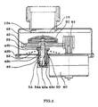
- Figure 3 shows another embodiment in which a stepping motor 40 transmits a rotational movement to the valve shaft 22 via a mechanical drive device.
- This device consists for example of a toothed ring 42 fitted on the valve shaft 22 and which cooperates with a drive pinion 44 which is connected to the motor 40, said motor driving said pinion 44 in rotation around a second axis parallel to the valve axis 22.
- the drive pinion 44 shown in Figure 3 has a dimension in a direction parallel to the valve axis, called height, which corresponds to the axial displacement of the valve and the crown 42 has a lower height for reasons of space .
- the pinion and the ring gear have substantially the same height or that only the ring gear is of a height which corresponds to the axial displacement. of the valve.
- the pinion 44 has for example thirteen teeth and the crown 42 has for example fifty five teeth.
- the pinion and the crown both have straight teeth, but this could also be helical.
- the ring gear 42 is arranged between the valve 20 and the piece forming a nut 46, thus ensuring a minimal bulk.
- the piece forming a nut 46 consists of a cylindrical sleeve 46a provided at its upper end with a shoulder 46b.
- the metal frame 48 comprises a base 48b in which is formed an orifice 50 which receives the cylindrical sleeve 46a of the part forming a nut.
- An annular rim 48c is provided at the periphery of the sleeve 46a to serve as a support for the shoulder 46a of the piece forming a nut 46.
- An elastic member such as a helical spring 52 is held in the compressed position between the base 48b and the shoulder 46b and therefore exerts an upwardly directed force under the shoulder intended to bring the valve 20 into contact with its seat. 12a.
- the cylindrical sleeve 46a crosses the orifice 50 and opens on the other side of the base 48b.
- a so-called fuse element 54 made of a material melting under the action of heat is placed under the base 48b pressing against it and exerts on the nut-forming part an effort which tends to compensate for the compressive force of the elastic member 52.
- the fusible element 54 made of hard plastic has for example a general shape of a cup covering the part of the sleeve 46a which projects relative to the base so as to bear on said base by a flange and which comprises several claws 54a retracted towards the inside of said cup so as to engage in a groove 46c formed on the outside surface of the cylindrical sleeve 46a, thus preventing said sleeve from going upwards under the influence of spring 52.
- the fusible element 54 made of hard plastic has for example a general shape of a cup covering the part of the sleeve 46a which projects relative to the base so as to bear on said base by a flange and which comprises several claws 54a retracted towards the inside of said cup so as to engage in a groove 46c formed on the outside surface of the cylindrical sleeve 46a, thus preventing said sleeve from going upwards under the influence of spring 52.
- FIG. 4 represents an alternative embodiment of the elastic member of FIG. 3.
- the elastic member is a leaf spring as shown in section in FIG. 5. It is of course possible to use other types of elastic member to fulfill this function.
- the mechanical drive device of the valve shaft 22 from the engine is not limited to what has just been described. Indeed, this device can for example consist of a smooth or toothed belt mounted on the valve axis and on the axis exiting the engine.
- the fire-fighting system made up of the elastic member and the fusible element can also be adapted to the cut-off member shown in FIG. 2. It should be noted that the presence of the elastic member and the fusible element is not always desired.
Landscapes
- Engineering & Computer Science (AREA)
- General Engineering & Computer Science (AREA)
- Physics & Mathematics (AREA)
- Mechanical Engineering (AREA)
- Fluid Mechanics (AREA)
- General Physics & Mathematics (AREA)
- Electromagnetism (AREA)
- Health & Medical Sciences (AREA)
- Public Health (AREA)
- Business, Economics & Management (AREA)
- Emergency Management (AREA)
- Measuring Volume Flow (AREA)
- Electrically Driven Valve-Operating Means (AREA)
- Safety Valves (AREA)
- Lift Valve (AREA)
Claims (16)
- Organ (14) zur Unterbrechung des Gasstroms eines Gaszählers (10) mit einem in bezug auf einen Ventilsitz (12a) in Längsrichtung beweglichen Ventilelement (20), wobei das Ventilelement mit einem Ventilschaft (22) verbunden ist, der entsprechend dieser Längsrichtung ausgerichtet ist, dadurch gekennzeichnet, daß mindestens ein Teil des Ventilschafts (22) ein Außengewinde aufweist und mit einem Teil (24; 46) zusammenwirkt, das diesen Teil des Ventilschafts umgibt und eine Mutter bildet, wobei der Ventilschaft (22) somit eine schraubenförmige Bewegung ausführt.
- Organ nach Anspruch 1, bei dem das Ventilelement (20) frei drehbar auf dem Ventilschaft (22) angebracht ist.
- Organ nach Anspruch 1 oder 2, mit einem Motor (26; 40), der die Ventilschaft (22) drehbeweglich in Drehung versetzt.
- Organ nach Anspruch 3, bei dem der Motor (26) an einem Ende (22a) des Ventilschafts (22) angebracht ist, das gegenüber dem Ende (22b) des Schafts liegt, an welchem sich das Ventilelement befindet.
- Organ nach den Ansprüchen 3 und 4, bei dem der Motor (40) dem Ventilschaft (22) die Drehbewegung über eine mechanische Antriebsvorrichtung überträgt.
- Organ nach Anspruch 5, bei dem der Ventilschaft (22) einen Zahnkranz (42) trägt, der auf den Schaft aufgesteckt ist und mit einem vom Motor (40) um eine zweite, in bezug auf den Ventilschaft (22) parallele Achse in Drehung versetzten Ritzel (44) zusammenwirkt, wobei das Ritzel mit dem Motor verbunden ist.
- Organ nach Anspruch 6, bei dem das Ritzel (44) in einer zum Ventilschaft (22) parallelen Richtung eine der axialen Verstellung des Ventilelements entsprechenden Abmessung aufweist.
- Organ nach Anspruch 6, bei dem der Zahnkranz (42) zwischen dem Ventilelement (20) und dem die Mutter (46) bildenden Teil angeordnet ist.
- Organ nach einem der Ansprüche 3 bis 8, bei dem der Motor (26; 40) ein Schrittmotor ist.
- Organ nach Anspruch 4 oder 6, bei dem das die Mutter (46) bildende Teil der Wirkung eines federnden Organs (52) ausgesetzt ist, das das Teil und somit das Ventilelement (20) näher an den Ventilsitz (12a) zu bringen sucht, und das in seiner Stellung mittels eines schmelzbaren Elements (54) gehalten ist, das aus einem unter Hitzeeinwirkung schmelzenden Material gebildet ist.
- Organ nach Anspruch 10, bei dem das die Mutter (46) bildende Teil in einer in einer Grundplatte (48b) angebrachten Öffnung (50) gelagert ist und eine Schulter (46b) aufweist, wobei das federnde Organ zwischen der Grundplatte und der Schulter zusammengedrückt ist, um auf das Teil eine Kraft auszuüben, die es näher an den Ventilsitz (12) zu bringen sucht.
- Organ nach Anspruch 11, bei dem das die Mutter (46) bildende Teil durch die Öffnung (50) hindurchgeht und aus der Grundplatte (48b) auf der Seite herausragt, die der Seite gegenüberliegt, an der sich das federnde Organ befindet, wobei das schmelzbare Element (54) in Anlage an der Grundplatte gehalten ist und auf das Teil eine Kraft ausübt, die es vom Ventilsitz (12a) zu entfernen sucht.
- Organ nach Anspruch 12, bei dem die Grundplatte (48b) aus einem wärmeleitenden Material besteht und Teil eines Gehäuses (48) ist, das aus dem gleichen Material besteht und die Grundplatte mit dem Ventilsitz verbindet.
- Gaszähler mit einer Meßeinheit, der mit einem in bezug auf die Meßeinheit in Strömungsrichtung eines in den Zähler fließenden Gasstroms stromaufwärts angeordneten Organ (14) zur Unterbrechung des Gasstroms ausgestattet ist, wobei das Unterbrechungsorgan ein in bezug auf den Ventilsitz (12a) in einer Längsrichtung bewegliches Ventilelement (20) enthält, wobei das Ventilelement mit einem Ventilschaft (22) verbunden ist, der entlang dieser Längsrichtung ausgerichtet ist, dadurch gekennzeichnet, daß mindestens ein Teil des Ventilschafts ein Außengewinde aufweist und mit einem Teil (24; 46) zusammenwirkt, das den Teil des Schafts umgibt und eine Mutter bildet, wobei der Ventilschaft somit eine schraubenförmige Bewegung ausführt.
- Gaszähler nach Anspruch 14, bei dem das Unterbrechungsorgan (14) innerhalb des Zählers (10) angeordnet ist.
- Gaszähler nach Anspruch 14 oder 15, bei dem das Unterbrechungsorgan (14) die Merkmale eines der Ansprüche 2 bis 13 aufweist.
Applications Claiming Priority (3)
| Application Number | Priority Date | Filing Date | Title |
|---|---|---|---|
| FR9508112A FR2736430B1 (fr) | 1995-07-05 | 1995-07-05 | Organe de coupure antifraude pour compteur de gaz et compteur de gaz equipe d'un tel organe de coupure |
| FR9508112 | 1995-07-05 | ||
| PCT/FR1996/001046 WO1997002471A1 (fr) | 1995-07-05 | 1996-07-04 | Organe de coupure antifraude pour compteur de gaz et compteur de gaz equipe d'un tel organe de coupure |
Publications (2)
| Publication Number | Publication Date |
|---|---|
| EP0836701A1 EP0836701A1 (de) | 1998-04-22 |
| EP0836701B1 true EP0836701B1 (de) | 1999-02-03 |
Family
ID=9480703
Family Applications (1)
| Application Number | Title | Priority Date | Filing Date |
|---|---|---|---|
| EP96924937A Expired - Lifetime EP0836701B1 (de) | 1995-07-05 | 1996-07-04 | Betrugsverhinderndes schaltorgan für gaszähler und gaszähler damit |
Country Status (14)
| Country | Link |
|---|---|
| EP (1) | EP0836701B1 (de) |
| KR (1) | KR19990028670A (de) |
| CN (1) | CN1095073C (de) |
| AR (1) | AR002695A1 (de) |
| BR (1) | BR9609665A (de) |
| DE (1) | DE69601506T2 (de) |
| ES (1) | ES2130839T3 (de) |
| FR (1) | FR2736430B1 (de) |
| HU (1) | HUP9901334A2 (de) |
| MX (1) | MX9800257A (de) |
| PL (1) | PL180950B1 (de) |
| TR (1) | TR199600563A2 (de) |
| UA (1) | UA48975C2 (de) |
| WO (1) | WO1997002471A1 (de) |
Cited By (2)
| Publication number | Priority date | Publication date | Assignee | Title |
|---|---|---|---|---|
| EP2843277A1 (de) | 2013-09-02 | 2015-03-04 | Johnson Electric S.A. | Gasabsperrventil |
| EP3106727A1 (de) | 2015-06-17 | 2016-12-21 | Johnson Electric S.A. | Absperrventil zur integration in einen gaszähler |
Families Citing this family (7)
| Publication number | Priority date | Publication date | Assignee | Title |
|---|---|---|---|---|
| FR2949273B1 (fr) | 2009-08-21 | 2015-09-25 | Christian Carme | Barriere acoustique ajouree permettant un traitement hybride passif/actif du bruit |
| CN103629430B (zh) * | 2013-12-07 | 2016-01-20 | 四川海力智能科技有限公司 | 电机阀 |
| CN103644362A (zh) * | 2013-12-07 | 2014-03-19 | 四川海力智能科技有限公司 | 电机阀 |
| AT14492U1 (de) * | 2014-08-20 | 2015-12-15 | Linz Gas Wärme Gmbh Für Erdgas Und Wärmeversorgung | Sperrplatte zur Absperrung von Geräten und Anlagen |
| UA109390C2 (uk) * | 2015-03-06 | 2015-08-10 | Система автоматичного управління газовим потоком | |
| CN107304851B (zh) * | 2016-04-19 | 2020-04-21 | 乐清杰奔电子有限公司 | 一种适用于燃气表的控制阀 |
| CN106090409A (zh) * | 2016-08-15 | 2016-11-09 | 无锡惠山泵业有限公司 | 一种适用性强的阀门 |
Family Cites Families (2)
| Publication number | Priority date | Publication date | Assignee | Title |
|---|---|---|---|---|
| EP0117208A1 (de) * | 1983-02-17 | 1984-08-29 | COMPAGNIE PARISIENNE D'OUTILLAGE A AIR COMPRIME Société anonyme dite: | Hydraulischer Servodruckbegrenzer |
| DE58907586D1 (de) * | 1989-12-04 | 1994-06-01 | Siemens Ag | Gasverbrauchsmesseinrichtung. |
-
1995
- 1995-07-05 FR FR9508112A patent/FR2736430B1/fr not_active Expired - Fee Related
-
1996
- 1996-07-04 HU HU9901334A patent/HUP9901334A2/hu unknown
- 1996-07-04 CN CN96196159A patent/CN1095073C/zh not_active Expired - Fee Related
- 1996-07-04 EP EP96924937A patent/EP0836701B1/de not_active Expired - Lifetime
- 1996-07-04 BR BR9609665A patent/BR9609665A/pt not_active Application Discontinuation
- 1996-07-04 UA UA98010041A patent/UA48975C2/uk unknown
- 1996-07-04 WO PCT/FR1996/001046 patent/WO1997002471A1/fr active IP Right Grant
- 1996-07-04 KR KR1019970709993A patent/KR19990028670A/ko active IP Right Grant
- 1996-07-04 DE DE69601506T patent/DE69601506T2/de not_active Expired - Fee Related
- 1996-07-04 ES ES96924937T patent/ES2130839T3/es not_active Expired - Lifetime
- 1996-07-04 PL PL96324426A patent/PL180950B1/pl unknown
- 1996-07-04 MX MX9800257A patent/MX9800257A/es not_active IP Right Cessation
- 1996-07-05 AR ARP960103465A patent/AR002695A1/es unknown
- 1996-07-05 TR TR96/00563A patent/TR199600563A2/xx unknown
Cited By (6)
| Publication number | Priority date | Publication date | Assignee | Title |
|---|---|---|---|---|
| EP2843277A1 (de) | 2013-09-02 | 2015-03-04 | Johnson Electric S.A. | Gasabsperrventil |
| DE102013109570A1 (de) | 2013-09-02 | 2015-03-19 | Johnson Electric Germany GmbH & Co. KG | Gasabschaltventil |
| DE102013109570B4 (de) * | 2013-09-02 | 2017-07-20 | Johnson Electric Germany GmbH & Co. KG | Gasabschaltventil |
| EP3106727A1 (de) | 2015-06-17 | 2016-12-21 | Johnson Electric S.A. | Absperrventil zur integration in einen gaszähler |
| DE102015109694A1 (de) | 2015-06-17 | 2016-12-22 | Johnson Electric Germany GmbH & Co. KG | Absperrventil für den Einbau in Gaszähler und Verfahren zum Betreiben desselben |
| DE102015109694B4 (de) * | 2015-06-17 | 2017-06-29 | Johnson Electric Germany GmbH & Co. KG | Absperrventil für den Einbau in Gaszähler und Verfahren zum Betreiben desselben |
Also Published As
| Publication number | Publication date |
|---|---|
| KR19990028670A (ko) | 1999-04-15 |
| UA48975C2 (uk) | 2002-09-16 |
| FR2736430A1 (fr) | 1997-01-10 |
| PL180950B1 (pl) | 2001-05-31 |
| BR9609665A (pt) | 1999-03-30 |
| AR002695A1 (es) | 1998-03-25 |
| WO1997002471A1 (fr) | 1997-01-23 |
| FR2736430B1 (fr) | 1997-10-03 |
| DE69601506D1 (de) | 1999-03-18 |
| HUP9901334A2 (hu) | 1999-08-30 |
| MX9800257A (es) | 1998-04-30 |
| ES2130839T3 (es) | 1999-07-01 |
| TR199600563A2 (tr) | 1997-01-21 |
| PL324426A1 (en) | 1998-05-25 |
| CN1095073C (zh) | 2002-11-27 |
| EP0836701A1 (de) | 1998-04-22 |
| CN1192805A (zh) | 1998-09-09 |
| DE69601506T2 (de) | 1999-09-02 |
Similar Documents
| Publication | Publication Date | Title |
|---|---|---|
| EP1698815A1 (de) | Sicherheitsabsperrventilsteuereinrichtung eines Gasdruckreglers | |
| EP0836701B1 (de) | Betrugsverhinderndes schaltorgan für gaszähler und gaszähler damit | |
| EP0836702B1 (de) | Durchflussunterbrecher mit feuerschutzventil für gaszähler | |
| WO2014009279A1 (fr) | Robinet detendeur avec fonction de pression residuelle integree dans le detendeur | |
| FR2877743A1 (fr) | Dispositif de regulation de debit | |
| EP2565353B1 (de) | Vorrichtung zum Verriegeln und Entriegeln mit Hilfe eines Schlüssels einer Abdeckung auf einem Rahmen mit integrierter Verschlusseinlage eines Öffnungselements der Abdeckung für das Einführen des Schlüssels | |
| FR2899300A1 (fr) | Dispositif de valve de bouteille de gaz liquefie | |
| FR2472516A1 (fr) | Bouchon d'une seule piece en matiere plastique | |
| WO2005089880A1 (fr) | Extincteur portatif | |
| EP2572126B1 (de) | Zylinderventil mit restdruckventil | |
| FR2599110A1 (fr) | Robinet equipe de clapets d'obturation et anti-retour | |
| EP1215424B1 (de) | Sicherheitsgasventil | |
| FR2666992A1 (fr) | Dispositif de securite pour bac de stockage de produits inflammables. | |
| FR2714954A1 (fr) | Dispositif de remise automatique en position ouverte ou fermée de l'arbre rotatif d'une vanne d'arrêt. | |
| CH703622A2 (fr) | Poussoir a seuil de declenchement pour piece d'horlogerie. | |
| FR2736432A1 (fr) | Compteur de gaz equipe d'un organe de coupure motorise | |
| EP1317636B1 (de) | Druckminderungsventil zur schnellmontage auf eine gasflasche | |
| EP1205826A1 (de) | Einstellvorrichtung für eine Uhr vom angeschraubten Krone Typ | |
| FR2706192A1 (fr) | Dispositif à clapet pour couper un circuit de fluide en cas d'incendie. | |
| FR2878309A1 (fr) | Vanne, notamment robinet thermostatique | |
| FR2882796A1 (fr) | Dispositif d'assemblage de panneaux superposes | |
| EP1659459A1 (de) | Schutzvorrichtung für den Zugang der Aufzugseinrichtung einer Taschenuhr | |
| FR2462376A1 (fr) | Perfectionnement aux devidoirs | |
| FR2734020A1 (fr) | Portillon mecanique | |
| EP0667471A1 (de) | Ventil zum Absperren eines Fluidkreislaufes im Falle eines Brandes |
Legal Events
| Date | Code | Title | Description |
|---|---|---|---|
| PUAI | Public reference made under article 153(3) epc to a published international application that has entered the european phase |
Free format text: ORIGINAL CODE: 0009012 |
|
| 17P | Request for examination filed |
Effective date: 19980203 |
|
| AK | Designated contracting states |
Kind code of ref document: A1 Designated state(s): DE ES FR GB IT NL |
|
| GRAG | Despatch of communication of intention to grant |
Free format text: ORIGINAL CODE: EPIDOS AGRA |
|
| GRAG | Despatch of communication of intention to grant |
Free format text: ORIGINAL CODE: EPIDOS AGRA |
|
| GRAH | Despatch of communication of intention to grant a patent |
Free format text: ORIGINAL CODE: EPIDOS IGRA |
|
| 17Q | First examination report despatched |
Effective date: 19980716 |
|
| GRAH | Despatch of communication of intention to grant a patent |
Free format text: ORIGINAL CODE: EPIDOS IGRA |
|
| GRAA | (expected) grant |
Free format text: ORIGINAL CODE: 0009210 |
|
| AK | Designated contracting states |
Kind code of ref document: B1 Designated state(s): DE ES FR GB IT NL |
|
| REF | Corresponds to: |
Ref document number: 69601506 Country of ref document: DE Date of ref document: 19990318 |
|
| ITF | It: translation for a ep patent filed |
Owner name: BARZANO' E ZANARDO MILANO S.P.A. |
|
| GBT | Gb: translation of ep patent filed (gb section 77(6)(a)/1977) |
Effective date: 19990421 |
|
| REG | Reference to a national code |
Ref country code: ES Ref legal event code: FG2A Ref document number: 2130839 Country of ref document: ES Kind code of ref document: T3 |
|
| PLBE | No opposition filed within time limit |
Free format text: ORIGINAL CODE: 0009261 |
|
| STAA | Information on the status of an ep patent application or granted ep patent |
Free format text: STATUS: NO OPPOSITION FILED WITHIN TIME LIMIT |
|
| 26N | No opposition filed | ||
| PGFP | Annual fee paid to national office [announced via postgrant information from national office to epo] |
Ref country code: ES Payment date: 20010719 Year of fee payment: 6 |
|
| REG | Reference to a national code |
Ref country code: GB Ref legal event code: IF02 |
|
| PG25 | Lapsed in a contracting state [announced via postgrant information from national office to epo] |
Ref country code: ES Free format text: LAPSE BECAUSE OF NON-PAYMENT OF DUE FEES Effective date: 20020705 |
|
| PGFP | Annual fee paid to national office [announced via postgrant information from national office to epo] |
Ref country code: DE Payment date: 20020710 Year of fee payment: 7 |
|
| PGFP | Annual fee paid to national office [announced via postgrant information from national office to epo] |
Ref country code: NL Payment date: 20020730 Year of fee payment: 7 |
|
| REG | Reference to a national code |
Ref country code: FR Ref legal event code: GC |
|
| PG25 | Lapsed in a contracting state [announced via postgrant information from national office to epo] |
Ref country code: NL Free format text: LAPSE BECAUSE OF NON-PAYMENT OF DUE FEES Effective date: 20040201 |
|
| PG25 | Lapsed in a contracting state [announced via postgrant information from national office to epo] |
Ref country code: DE Free format text: LAPSE BECAUSE OF NON-PAYMENT OF DUE FEES Effective date: 20040203 |
|
| NLV4 | Nl: lapsed or anulled due to non-payment of the annual fee |
Effective date: 20040201 |
|
| REG | Reference to a national code |
Ref country code: ES Ref legal event code: FD2A Effective date: 20030811 |
|
| REG | Reference to a national code |
Ref country code: FR Ref legal event code: DG |
|
| REG | Reference to a national code |
Ref country code: GB Ref legal event code: 732E |
|
| REG | Reference to a national code |
Ref country code: FR Ref legal event code: TP |
|
| PGFP | Annual fee paid to national office [announced via postgrant information from national office to epo] |
Ref country code: FR Payment date: 20090716 Year of fee payment: 14 |
|
| PGFP | Annual fee paid to national office [announced via postgrant information from national office to epo] |
Ref country code: GB Payment date: 20090720 Year of fee payment: 14 |
|
| PGFP | Annual fee paid to national office [announced via postgrant information from national office to epo] |
Ref country code: IT Payment date: 20090725 Year of fee payment: 14 |
|
| GBPC | Gb: european patent ceased through non-payment of renewal fee |
Effective date: 20100704 |
|
| REG | Reference to a national code |
Ref country code: FR Ref legal event code: ST Effective date: 20110331 |
|
| PG25 | Lapsed in a contracting state [announced via postgrant information from national office to epo] |
Ref country code: FR Free format text: LAPSE BECAUSE OF NON-PAYMENT OF DUE FEES Effective date: 20100802 Ref country code: IT Free format text: LAPSE BECAUSE OF NON-PAYMENT OF DUE FEES Effective date: 20100704 |
|
| PG25 | Lapsed in a contracting state [announced via postgrant information from national office to epo] |
Ref country code: GB Free format text: LAPSE BECAUSE OF NON-PAYMENT OF DUE FEES Effective date: 20100704 |