EP0834947B1 - Method for excluding a malfunctioning elementary cell in a membrane electrolyzer or fuel cell generator - Google Patents
Method for excluding a malfunctioning elementary cell in a membrane electrolyzer or fuel cell generator Download PDFInfo
- Publication number
- EP0834947B1 EP0834947B1 EP97117182A EP97117182A EP0834947B1 EP 0834947 B1 EP0834947 B1 EP 0834947B1 EP 97117182 A EP97117182 A EP 97117182A EP 97117182 A EP97117182 A EP 97117182A EP 0834947 B1 EP0834947 B1 EP 0834947B1
- Authority
- EP
- European Patent Office
- Prior art keywords
- gaskets
- perforations
- bipolar plates
- malfunctioning
- membrane
- Prior art date
- Legal status (The legal status is an assumption and is not a legal conclusion. Google has not performed a legal analysis and makes no representation as to the accuracy of the status listed.)
- Expired - Lifetime
Links
Images


Classifications
-
- C—CHEMISTRY; METALLURGY
- C25—ELECTROLYTIC OR ELECTROPHORETIC PROCESSES; APPARATUS THEREFOR
- C25B—ELECTROLYTIC OR ELECTROPHORETIC PROCESSES FOR THE PRODUCTION OF COMPOUNDS OR NON-METALS; APPARATUS THEREFOR
- C25B15/00—Operating or servicing cells
-
- H—ELECTRICITY
- H01—ELECTRIC ELEMENTS
- H01M—PROCESSES OR MEANS, e.g. BATTERIES, FOR THE DIRECT CONVERSION OF CHEMICAL ENERGY INTO ELECTRICAL ENERGY
- H01M8/00—Fuel cells; Manufacture thereof
- H01M8/02—Details
- H01M8/0271—Sealing or supporting means around electrodes, matrices or membranes
-
- H—ELECTRICITY
- H01—ELECTRIC ELEMENTS
- H01M—PROCESSES OR MEANS, e.g. BATTERIES, FOR THE DIRECT CONVERSION OF CHEMICAL ENERGY INTO ELECTRICAL ENERGY
- H01M8/00—Fuel cells; Manufacture thereof
- H01M8/04—Auxiliary arrangements, e.g. for control of pressure or for circulation of fluids
- H01M8/04223—Auxiliary arrangements, e.g. for control of pressure or for circulation of fluids during start-up or shut-down; Depolarisation or activation, e.g. purging; Means for short-circuiting defective fuel cells
-
- H—ELECTRICITY
- H01—ELECTRIC ELEMENTS
- H01M—PROCESSES OR MEANS, e.g. BATTERIES, FOR THE DIRECT CONVERSION OF CHEMICAL ENERGY INTO ELECTRICAL ENERGY
- H01M8/00—Fuel cells; Manufacture thereof
- H01M8/24—Grouping of fuel cells, e.g. stacking of fuel cells
- H01M8/2465—Details of groupings of fuel cells
- H01M8/2483—Details of groupings of fuel cells characterised by internal manifolds
-
- H—ELECTRICITY
- H01—ELECTRIC ELEMENTS
- H01M—PROCESSES OR MEANS, e.g. BATTERIES, FOR THE DIRECT CONVERSION OF CHEMICAL ENERGY INTO ELECTRICAL ENERGY
- H01M2300/00—Electrolytes
- H01M2300/0017—Non-aqueous electrolytes
- H01M2300/0065—Solid electrolytes
- H01M2300/0082—Organic polymers
-
- Y—GENERAL TAGGING OF NEW TECHNOLOGICAL DEVELOPMENTS; GENERAL TAGGING OF CROSS-SECTIONAL TECHNOLOGIES SPANNING OVER SEVERAL SECTIONS OF THE IPC; TECHNICAL SUBJECTS COVERED BY FORMER USPC CROSS-REFERENCE ART COLLECTIONS [XRACs] AND DIGESTS
- Y02—TECHNOLOGIES OR APPLICATIONS FOR MITIGATION OR ADAPTATION AGAINST CLIMATE CHANGE
- Y02E—REDUCTION OF GREENHOUSE GAS [GHG] EMISSIONS, RELATED TO ENERGY GENERATION, TRANSMISSION OR DISTRIBUTION
- Y02E60/00—Enabling technologies; Technologies with a potential or indirect contribution to GHG emissions mitigation
- Y02E60/30—Hydrogen technology
- Y02E60/36—Hydrogen production from non-carbon containing sources, e.g. by water electrolysis
-
- Y—GENERAL TAGGING OF NEW TECHNOLOGICAL DEVELOPMENTS; GENERAL TAGGING OF CROSS-SECTIONAL TECHNOLOGIES SPANNING OVER SEVERAL SECTIONS OF THE IPC; TECHNICAL SUBJECTS COVERED BY FORMER USPC CROSS-REFERENCE ART COLLECTIONS [XRACs] AND DIGESTS
- Y02—TECHNOLOGIES OR APPLICATIONS FOR MITIGATION OR ADAPTATION AGAINST CLIMATE CHANGE
- Y02E—REDUCTION OF GREENHOUSE GAS [GHG] EMISSIONS, RELATED TO ENERGY GENERATION, TRANSMISSION OR DISTRIBUTION
- Y02E60/00—Enabling technologies; Technologies with a potential or indirect contribution to GHG emissions mitigation
- Y02E60/30—Hydrogen technology
- Y02E60/50—Fuel cells
-
- Y—GENERAL TAGGING OF NEW TECHNOLOGICAL DEVELOPMENTS; GENERAL TAGGING OF CROSS-SECTIONAL TECHNOLOGIES SPANNING OVER SEVERAL SECTIONS OF THE IPC; TECHNICAL SUBJECTS COVERED BY FORMER USPC CROSS-REFERENCE ART COLLECTIONS [XRACs] AND DIGESTS
- Y02—TECHNOLOGIES OR APPLICATIONS FOR MITIGATION OR ADAPTATION AGAINST CLIMATE CHANGE
- Y02P—CLIMATE CHANGE MITIGATION TECHNOLOGIES IN THE PRODUCTION OR PROCESSING OF GOODS
- Y02P70/00—Climate change mitigation technologies in the production process for final industrial or consumer products
- Y02P70/50—Manufacturing or production processes characterised by the final manufactured product
Definitions
- Known in the art are electrolysis or power generation processes carried out in filter-press structures comprising an arrangement of electrochemical cells.
- the typical elementary electrochemical cell suitable for said processes usually has a reduced thickness in order to minimize the energy consumption.
- the elementary cell is delimited by two conductive plates enclosing a couple of peripheral sealing gaskets, an ion exchange membrane, a couple of electrodes and a couple of current collectors/distributors.
- the plates and/or gaskets have holes connecting the anodic and cathodic compartments by means of distribution channels.
- a multiplicity of elementary cells is generally assembled in a filter-press arrangement to form an electrolyzer or electric current generator.
- the electrolyzer or generator is made of a series of bipolar plates, gaskets, membranes, electrodes and current collectors/distributors.
- the alignment of the holes in the plates and gaskets forms longitudinal ducts which are connected to suitable nozzles positioned at one or both ends of the electrolyzer or generator.
- the reactants and the reaction products are fed or withdrawn through these nozzles and ducts.
- Distribution channels permit feeding the reactants to each elementary cell and withdrawing the products and residual reactants therefrom.
- EP 0629015 A1 solves only partially the problem as it allows the electric current to by-pass the malfunctioning cell but does not eliminate possible inconveniences connected with the mixing of the reactants and/or products in case of damages to the membrane.
- reactants and products are in any case present in the elementary cell containing the damaged membrane due to the connection between the cell and the longitudinal feed and withdrawal ducts through the distribution channels.
- a damaged membrane not only hinders operation of the electrolyzer or generator, as it happens when the electrodes or the current collectors/distributors are defective, but also poses safety problems.
- an efficient repairing method is not found in the prior art.
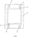
- Fig. 2 and 3 show respectively one elementary cell of the electrolyzer or generator of fig. 1 and the housing of a current collector/distributor (3) and of a catalytic electrode (4) inside a first type of gasket (5).
- reference numeral (8) identifies the holes for feeding and withdrawing the reactants and the reaction products and reference numeral (9) identifies the distribution channels incorporated in the gasket body which connect holes (8) with the cavity (indentation) formed in the gasket and occupied by the porous current collector/distributor (3) and by the electrode (4). Similar holes (not shown in the figures) are present in the bipolar plates (2).
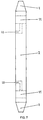
- the arrangement of a multiplicity of gaskets and bipolar plates, with the consequent alignment and coupling of the holes (8) of the gaskets and of the bipolar plates forms longitudinal channels crossing the whole assembly of the electrolyzer or generator of fig. 1. These channels provide for the distribution of the reactants to all the elementary cells and for the withdrawal of the reaction products from the same.
- FIG. 5 Different embodiments of the distribution channels are shown in fig. 5 and 6.
- the distributor channels are incorporated in the bipolar plates (2) as an alternative to gaskets (5).
- the distribution channels are identified by reference numeral (10) and the holes by reference numeral (11).
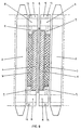
- Another embodiment of fig. 6 is shown in fig. 7 and in fig. 8.
- the distribution channels are incorporated both in the bipolar plates (2) and in the gaskets (5). This is substantially a combination of the embodiments shown in figs. 3 and 5.
- the advantage offered by this embodiment is the higher flow section available for the distribution of the reactants and the withdrawal of the products, particularly useful in the case of large size electrolyzers or generators.
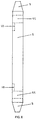
- the bipolar plates (2) and the gaskets (5) of figs. 3, 4, 5, 6, 7 e 8 are assembled together with the current collectors/distributors (3), electrodes (4) and ion exchange membranes (6) to form the electric current generator or electrolyzer schematically shown in fig. 1.
- the voltage When one of the elementary cells is malfunctioning, as a consequence of an erroneous assembling or defects in the components, its voltage remarkably differs from the average value of the other cells. Therefore a periodical measurement of the electric voltages of the elementary cells during operation of the electrolyzer or generator permits to quickly detect anomalies.
- the method of the present invention permits to keep the electrolyzer or generator operating under safe conditions without any need to open and disassemble the same.
- the method of the present invention comprises perforating, by means of a suitable tool, for example an electric or manual boring machine having a drill of suitable diameter, the peripheral area of the elements of the malfunctioning unitary cell wherein the distribution channels are incorporated, such as the gaskets (see figs. 3 and 5) or the bipolar plates (see figs. 6 and 7). Perforation is carried out without disassembling or opening the electrolyzer or generator.
- the gaskets or bipolar plates to be perforated are those enclosing the pair of electrodes characterized by an anomalous electric voltage.
- the distributor channels are incorporated in the gaskets (5), as illustrated in fig. 5.
- Fig. 9 dearly shows that the perforations (12) are made in correspondence of the holes (8) which are connected with the distribution channels (9).
- the peripheral area of the gaskets (5) contains blind aid-holes (13) aligned with the respective distribution channels (9), as shown in fig. 10, which schematizes a detail of the gasket (5) of the type illustrated in fig. 5.
- the holes (13) have the function of guiding the perforation drill so that once the procedure is completed the perforation (12) makes the respective distribution channel perfectly accessible.
- the method of the invention comprises injecting, by means of a suitable tool, such as a syringe provided with a thin needle, a sealing agent inside the distribution channels (9) and then inside the perforations (12).
- a suitable tool such as a syringe provided with a thin needle
- the two steps of the sealing procedure are schematized in fig. 11, illustrating a detail of the gasket of the type represented in fig. 5.
- Reference numerals (14) and (15) indicate respectively the occlusions of the distribution channels (9) and of the perforations (12).
- Reference numeral (16) indicates the injecting tool.
- the sealing agent once hardened, performs two distinct functions: the portion occluding the perforations (12) ensures sealing against the environment to avoid gas emissions or fluid leakage even when the electrolyzer or generator operates under pressure, while the portion occluding the distribution channels (9) ensures for a perfect separation of the compartments containing the current collectors/distributors and the electrodes from the longitudinal ducts for feeding the reactants and withdrawing the products.
- the number of perforations may be reduced and consequently only one compartment containing a current collector/distributor and one electrode is sealed. In this case only one gasket and/or only one bipolar plate are perforated. Obviously this procedure permits to save time but the reliability is lower than that ensured by sealing both compartments of the malfunctioning cell.
- the bipolar plates (2) of the malfunctioning elementary cell are short-circuited by means of connections (7) (in fig. 1), or the cell is excluded.
- the electrolyzer or generator may be then started up again under completely safe conditions.
- the short-circuiting or exclusion deviates or hinders the electric current flow and therefore the cells, without any current flowing therethrough, generate no products.
- the products and reactants contained in the longitudinal ducts cannot penetrate in the compartments of the malfunctioning cell. As a consequence, there is no risk of any dangerous mixing of reactants and products occurring through a defective membrane.
- the type of sealing agent to be used the following selection criteria must be taken into account:
- the invention applies also to electrolyzers or generators where the distribution channels are provided in the gaskets as illustrated in fig. 3 or in the bipolar plates as illustrated in figs. 6 and 7 or concurrently in the gaskets and bipolar plates as illustrated in fig 8. In all of these cases the procedure is exactly the same as described in connection with the embodiment of fig. 5. The perforation procedure is the same, likewise useful are the blind aid-holes and the sealing is carried out in the same way.
Landscapes
- Chemical & Material Sciences (AREA)
- Engineering & Computer Science (AREA)
- Chemical Kinetics & Catalysis (AREA)
- Electrochemistry (AREA)
- Sustainable Development (AREA)
- Life Sciences & Earth Sciences (AREA)
- Manufacturing & Machinery (AREA)
- Sustainable Energy (AREA)
- General Chemical & Material Sciences (AREA)
- Metallurgy (AREA)
- Organic Chemistry (AREA)
- Materials Engineering (AREA)
- Electrolytic Production Of Non-Metals, Compounds, Apparatuses Therefor (AREA)
- Fuel Cell (AREA)
Applications Claiming Priority (2)
| Application Number | Priority Date | Filing Date | Title |
|---|---|---|---|
| IT96MI002037A IT1284887B1 (it) | 1996-10-03 | 1996-10-03 | Metodo di esclusione di una cella elementare malfunzionante di un elettrolizzatore o di un generatore elettrochimico a membrana |
| ITMI962037 | 1996-10-03 |
Publications (2)
| Publication Number | Publication Date |
|---|---|
| EP0834947A1 EP0834947A1 (en) | 1998-04-08 |
| EP0834947B1 true EP0834947B1 (en) | 2002-07-24 |
Family
ID=11374964
Family Applications (1)
| Application Number | Title | Priority Date | Filing Date |
|---|---|---|---|
| EP97117182A Expired - Lifetime EP0834947B1 (en) | 1996-10-03 | 1997-10-02 | Method for excluding a malfunctioning elementary cell in a membrane electrolyzer or fuel cell generator |
Country Status (15)
| Country | Link |
|---|---|
| US (1) | US5876583A (enExample) |
| EP (1) | EP0834947B1 (enExample) |
| JP (1) | JPH10121284A (enExample) |
| KR (1) | KR100449932B1 (enExample) |
| AT (1) | ATE221258T1 (enExample) |
| AU (1) | AU711670B2 (enExample) |
| BR (1) | BR9704967A (enExample) |
| CA (1) | CA2214926A1 (enExample) |
| DE (1) | DE69714176T2 (enExample) |
| DK (1) | DK0834947T3 (enExample) |
| ES (1) | ES2180870T3 (enExample) |
| ID (1) | ID17692A (enExample) |
| IT (1) | IT1284887B1 (enExample) |
| SG (1) | SG60117A1 (enExample) |
| TR (1) | TR199701112A2 (enExample) |
Families Citing this family (18)
| Publication number | Priority date | Publication date | Assignee | Title |
|---|---|---|---|---|
| ITMI20010458A1 (it) * | 2001-03-06 | 2002-09-06 | Nuvera Fuel Cells Europ Srl | Metodo di cortocircuitazione di una cella elettrochimica elementare malfunzionante di una struttura filtro-pressa |
| US6878477B2 (en) | 2001-05-15 | 2005-04-12 | Hydrogenics Corporation | Fuel cell flow field plate |
| JP2003109651A (ja) * | 2001-09-28 | 2003-04-11 | Mitsubishi Materials Corp | 固体電解質型燃料電池の補修方法 |
| ITMI20012342A1 (it) * | 2001-11-08 | 2003-05-08 | Nuvera Fuel Cells Europ Srl | Metodo per riutilizzare collettori/distributori di corrente di un generatore elettrochimico a membrana |
| US20040045682A1 (en) * | 2002-04-24 | 2004-03-11 | Randal Liprie | Cogeneration wasteheat evaporation system and method for wastewater treatment utilizing wasteheat recovery |
| KR20050010779A (ko) * | 2002-05-09 | 2005-01-28 | 더 보드 오브 트러스티스 오브 더 리랜드 스탠포드 주니어 유니버시티 | 개선된 연료전지 |
| DE10328255A1 (de) * | 2003-06-24 | 2005-01-13 | Daimlerchrysler Ag | Brennstoffzelle mit Kurzschlussmittel |
| US7358005B2 (en) * | 2003-09-18 | 2008-04-15 | General Electric Company | Methods and apparatus for isolating solid oxide fuel cells |
| WO2005028714A1 (en) | 2003-09-22 | 2005-03-31 | Hydrogenics Corporation | Apparatus and method for reducing instances of pump de-priming |
| US20050186458A1 (en) | 2003-09-22 | 2005-08-25 | Ali Rusta-Sallehy | Electrolyzer cell stack system |
| JP2007207586A (ja) * | 2006-02-02 | 2007-08-16 | Toyota Motor Corp | 燃料電池 |
| KR101171605B1 (ko) | 2010-12-28 | 2012-08-07 | 주식회사 포스코 | 고체산화물 연료전지 스택의 수리방법 |
| EP2872754A4 (en) * | 2012-07-02 | 2016-03-02 | Arthur Jeffs | HYDROGEN-BASED FUEL SUPPORT DEVICE FOR INTERNAL COMBUSTION ENGINE AND ASSOCIATED METHODS |
| US9915004B2 (en) | 2013-07-19 | 2018-03-13 | Nuvera Fuel Cells, LLC | System and method for tuning an electrochemical cell stack |
| CN105382483A (zh) * | 2015-11-05 | 2016-03-09 | 郑州发祥铝业有限公司 | 一种电解槽立柱母线短路口带电修复方法 |
| CN114144606B (zh) * | 2019-07-19 | 2022-11-04 | 迪诺拉永久电极股份有限公司 | 电解槽用密封垫及使用该电解槽用密封垫的电解槽 |
| DE102019217722B3 (de) * | 2019-11-18 | 2021-04-29 | Fraunhofer-Gesellschaft zur Förderung der angewandten Forschung e.V. | Anordnung elektrochemischer Zellen |
| KR102662952B1 (ko) * | 2022-04-12 | 2024-05-03 | 주식회사 테크로스 | 알칼라인 수전해 스택 조립체 |
Family Cites Families (8)
| Publication number | Priority date | Publication date | Assignee | Title |
|---|---|---|---|---|
| DE2503215C2 (de) * | 1975-01-27 | 1986-08-07 | Keramchemie GmbH, 5433 Siershahn | Vorrichtung zur Elektrolyse von Salzsäure |
| US4371433A (en) * | 1980-10-14 | 1983-02-01 | General Electric Company | Apparatus for reduction of shunt current in bipolar electrochemical cell assemblies |
| US4923582A (en) * | 1982-12-27 | 1990-05-08 | Eltech Systems Corporation | Monopolar, bipolar and/or hybrid memberane cell |
| JPS62246268A (ja) * | 1986-04-18 | 1987-10-27 | Sanyo Electric Co Ltd | 燃料電池の不良セル処理法 |
| JPS63307671A (ja) * | 1987-06-08 | 1988-12-15 | Ishikawajima Harima Heavy Ind Co Ltd | 積層燃料電池 |
| JPH04366561A (ja) * | 1991-06-11 | 1992-12-18 | Toshiba Corp | 燃料電池 |
| US5308713A (en) * | 1993-02-26 | 1994-05-03 | Modern Controls, Inc. | Process for the reactivating sealed liquid electrolyte batteries |
| IT1270878B (it) * | 1993-04-30 | 1997-05-13 | Permelec Spa Nora | Migliorata cella elettrochimica utilizzante membrane a scambio ionico e piatti bipolari metallici |
-
1996
- 1996-10-03 IT IT96MI002037A patent/IT1284887B1/it active IP Right Grant
-
1997
- 1997-09-08 US US08/936,494 patent/US5876583A/en not_active Expired - Fee Related
- 1997-09-08 CA CA002214926A patent/CA2214926A1/en not_active Abandoned
- 1997-09-09 AU AU36875/97A patent/AU711670B2/en not_active Ceased
- 1997-09-16 SG SG1997003424A patent/SG60117A1/en unknown
- 1997-10-01 KR KR1019970050784A patent/KR100449932B1/ko not_active Expired - Fee Related
- 1997-10-02 EP EP97117182A patent/EP0834947B1/en not_active Expired - Lifetime
- 1997-10-02 BR BR9704967A patent/BR9704967A/pt not_active IP Right Cessation
- 1997-10-02 DE DE69714176T patent/DE69714176T2/de not_active Expired - Lifetime
- 1997-10-02 AT AT97117182T patent/ATE221258T1/de not_active IP Right Cessation
- 1997-10-02 DK DK97117182T patent/DK0834947T3/da active
- 1997-10-02 ES ES97117182T patent/ES2180870T3/es not_active Expired - Lifetime
- 1997-10-03 JP JP9271394A patent/JPH10121284A/ja active Pending
- 1997-10-03 TR TR97/01112A patent/TR199701112A2/xx unknown
- 1997-10-03 ID IDP973354A patent/ID17692A/id unknown
Also Published As
| Publication number | Publication date |
|---|---|
| EP0834947A1 (en) | 1998-04-08 |
| SG60117A1 (en) | 1999-02-22 |
| AU711670B2 (en) | 1999-10-21 |
| DK0834947T3 (da) | 2002-11-18 |
| AU3687597A (en) | 1998-04-09 |
| TR199701112A2 (xx) | 1998-04-21 |
| IT1284887B1 (it) | 1998-05-22 |
| ITMI962037A1 (it) | 1998-04-03 |
| ATE221258T1 (de) | 2002-08-15 |
| DE69714176D1 (de) | 2002-08-29 |
| CA2214926A1 (en) | 1998-04-03 |
| ID17692A (id) | 1998-01-22 |
| DE69714176T2 (de) | 2003-03-27 |
| KR100449932B1 (ko) | 2005-01-13 |
| KR19980032471A (ko) | 1998-07-25 |
| ES2180870T3 (es) | 2003-02-16 |
| US5876583A (en) | 1999-03-02 |
| BR9704967A (pt) | 1998-12-29 |
| JPH10121284A (ja) | 1998-05-12 |
Similar Documents
| Publication | Publication Date | Title |
|---|---|---|
| EP0834947B1 (en) | Method for excluding a malfunctioning elementary cell in a membrane electrolyzer or fuel cell generator | |
| US6117287A (en) | Electrochemical cell frame | |
| CA2648655C (en) | Solid electrolyte fuel cell stack | |
| JP6479988B2 (ja) | 加圧下で動作する水電気分解もしくは共電解を実施するリアクタ(soec)または燃料セル(sofc)のための基本ユニット | |
| US6811915B2 (en) | Cell frame/flow field integration method and apparatus | |
| US10629936B2 (en) | Fuel cell stack | |
| JP2020519767A (ja) | 加圧動作に適したクランプシステムを有する、加圧動作用の水電解または共電解反応器(soec)または燃料セル(sofc) | |
| DE19953614A1 (de) | Brennstoffzellenanlage | |
| US20060228619A1 (en) | Electrochemical cell structure | |
| EP1444746A2 (de) | Verfahren zum lokalisieren eines gaslecks innerhalb einer brennstoffzellenanordnung | |
| EP1775790B1 (en) | Sofc assembly joint spacing | |
| JP4773055B2 (ja) | 燃料電池スタック、セパレータ中間体及びセパレータの製造方法 | |
| EP4371169A1 (de) | VERSCHWEIßTER ELEKTROCHEMISCHER REAKTOR UND VERFAHREN ZU DESSEN HERSTELLUNG | |
| CA2455063A1 (en) | Method and apparatus for locating internal transfer leaks within fuel cell stacks | |
| JP2024537841A (ja) | 主デバイスおよび補助デバイスを備えるエンドプレートを具備する燃料電池、燃料電池シャフトにアクセスするための方法 | |
| US20040214067A1 (en) | Assembling sub-stacks of electrochemical cells | |
| WO2018091520A2 (de) | Brennstoffzellenmodul, brennstoffzellensystem sowie betriebsverfahren | |
| US20250283236A1 (en) | Active tensioning for electrolyzer stacks | |
| DE102016122584A1 (de) | Verfahren zum Herstellen einer Bipolarplatte und Bipolarplatte | |
| WO2025242377A1 (de) | Dichtungsanordnung, zellelement einer elektrochemischen zelle, zellenstapel mit einer verteilerstruktur und elektrolyseur | |
| AU2024342144A1 (en) | Electrochemical reactor with circumferential seal | |
| JP2005183308A (ja) | 燃料電池用電圧検出装置の接続異常検出方法及び燃料電池の異常検出方法 | |
| JPS63307671A (ja) | 積層燃料電池 | |
| CA2915547A1 (en) | Start-up method for fuel cell system | |
| JPH0320970A (ja) | 燃料電池における電解質板中の結合剤除去方法 |
Legal Events
| Date | Code | Title | Description |
|---|---|---|---|
| PUAI | Public reference made under article 153(3) epc to a published international application that has entered the european phase |
Free format text: ORIGINAL CODE: 0009012 |
|
| AK | Designated contracting states |
Kind code of ref document: A1 Designated state(s): AT BE CH DE DK ES FI FR GB IT LI NL |
|
| 17P | Request for examination filed |
Effective date: 19981007 |
|
| AKX | Designation fees paid |
Free format text: AT BE CH DE DK ES FI FR GB IT LI NL |
|
| RBV | Designated contracting states (corrected) |
Designated state(s): AT BE CH DE DK ES FI FR GB IT LI NL |
|
| RAP1 | Party data changed (applicant data changed or rights of an application transferred) |
Owner name: DE NORA FUEL CELLS S.P.A. |
|
| GRAG | Despatch of communication of intention to grant |
Free format text: ORIGINAL CODE: EPIDOS AGRA |
|
| 17Q | First examination report despatched |
Effective date: 20010426 |
|
| RAP1 | Party data changed (applicant data changed or rights of an application transferred) |
Owner name: NUVERA FUEL CELLS EUROPE S.R.L. |
|
| GRAG | Despatch of communication of intention to grant |
Free format text: ORIGINAL CODE: EPIDOS AGRA |
|
| GRAG | Despatch of communication of intention to grant |
Free format text: ORIGINAL CODE: EPIDOS AGRA |
|
| GRAH | Despatch of communication of intention to grant a patent |
Free format text: ORIGINAL CODE: EPIDOS IGRA |
|
| GRAH | Despatch of communication of intention to grant a patent |
Free format text: ORIGINAL CODE: EPIDOS IGRA |
|
| GRAA | (expected) grant |
Free format text: ORIGINAL CODE: 0009210 |
|
| AK | Designated contracting states |
Kind code of ref document: B1 Designated state(s): AT BE CH DE DK ES FI FR GB IT LI NL |
|
| REF | Corresponds to: |
Ref document number: 221258 Country of ref document: AT Date of ref document: 20020815 Kind code of ref document: T |
|
| REG | Reference to a national code |
Ref country code: GB Ref legal event code: FG4D |
|
| REG | Reference to a national code |
Ref country code: CH Ref legal event code: EP |
|
| REF | Corresponds to: |
Ref document number: 69714176 Country of ref document: DE Date of ref document: 20020829 |
|
| PGFP | Annual fee paid to national office [announced via postgrant information from national office to epo] |
Ref country code: FI Payment date: 20021007 Year of fee payment: 6 |
|
| REG | Reference to a national code |
Ref country code: CH Ref legal event code: NV Representative=s name: FIAMMENGHI-FIAMMENGHI |
|
| REG | Reference to a national code |
Ref country code: DK Ref legal event code: T3 |
|
| ET | Fr: translation filed | ||
| REG | Reference to a national code |
Ref country code: ES Ref legal event code: FG2A Ref document number: 2180870 Country of ref document: ES Kind code of ref document: T3 |
|
| PLBE | No opposition filed within time limit |
Free format text: ORIGINAL CODE: 0009261 |
|
| STAA | Information on the status of an ep patent application or granted ep patent |
Free format text: STATUS: NO OPPOSITION FILED WITHIN TIME LIMIT |
|
| 26N | No opposition filed |
Effective date: 20030425 |
|
| PG25 | Lapsed in a contracting state [announced via postgrant information from national office to epo] |
Ref country code: FI Free format text: LAPSE BECAUSE OF NON-PAYMENT OF DUE FEES Effective date: 20031002 |
|
| PGFP | Annual fee paid to national office [announced via postgrant information from national office to epo] |
Ref country code: AT Payment date: 20061011 Year of fee payment: 10 |
|
| PGFP | Annual fee paid to national office [announced via postgrant information from national office to epo] |
Ref country code: CH Payment date: 20061012 Year of fee payment: 10 |
|
| PGFP | Annual fee paid to national office [announced via postgrant information from national office to epo] |
Ref country code: DK Payment date: 20061013 Year of fee payment: 10 |
|
| PGFP | Annual fee paid to national office [announced via postgrant information from national office to epo] |
Ref country code: NL Payment date: 20061016 Year of fee payment: 10 |
|
| PGFP | Annual fee paid to national office [announced via postgrant information from national office to epo] |
Ref country code: BE Payment date: 20061123 Year of fee payment: 10 |
|
| BERE | Be: lapsed |
Owner name: *NUVERA FUEL CELLS EUROPE S.R.L. Effective date: 20071031 |
|
| REG | Reference to a national code |
Ref country code: DK Ref legal event code: EBP |
|
| REG | Reference to a national code |
Ref country code: CH Ref legal event code: PL |
|
| NLV4 | Nl: lapsed or anulled due to non-payment of the annual fee |
Effective date: 20080501 |
|
| PG25 | Lapsed in a contracting state [announced via postgrant information from national office to epo] |
Ref country code: LI Free format text: LAPSE BECAUSE OF NON-PAYMENT OF DUE FEES Effective date: 20071031 Ref country code: CH Free format text: LAPSE BECAUSE OF NON-PAYMENT OF DUE FEES Effective date: 20071031 |
|
| PG25 | Lapsed in a contracting state [announced via postgrant information from national office to epo] |
Ref country code: AT Free format text: LAPSE BECAUSE OF NON-PAYMENT OF DUE FEES Effective date: 20071002 |
|
| PG25 | Lapsed in a contracting state [announced via postgrant information from national office to epo] |
Ref country code: BE Free format text: LAPSE BECAUSE OF NON-PAYMENT OF DUE FEES Effective date: 20071031 |
|
| PG25 | Lapsed in a contracting state [announced via postgrant information from national office to epo] |
Ref country code: NL Free format text: LAPSE BECAUSE OF NON-PAYMENT OF DUE FEES Effective date: 20080501 Ref country code: DK Free format text: LAPSE BECAUSE OF NON-PAYMENT OF DUE FEES Effective date: 20071031 |
|
| PGFP | Annual fee paid to national office [announced via postgrant information from national office to epo] |
Ref country code: ES Payment date: 20091023 Year of fee payment: 13 Ref country code: DE Payment date: 20091026 Year of fee payment: 13 |
|
| PGFP | Annual fee paid to national office [announced via postgrant information from national office to epo] |
Ref country code: IT Payment date: 20091028 Year of fee payment: 13 Ref country code: GB Payment date: 20091022 Year of fee payment: 13 Ref country code: FR Payment date: 20091110 Year of fee payment: 13 |
|
| GBPC | Gb: european patent ceased through non-payment of renewal fee |
Effective date: 20101002 |
|
| PG25 | Lapsed in a contracting state [announced via postgrant information from national office to epo] |
Ref country code: FR Free format text: LAPSE BECAUSE OF NON-PAYMENT OF DUE FEES Effective date: 20101102 |
|
| REG | Reference to a national code |
Ref country code: FR Ref legal event code: ST Effective date: 20110630 |
|
| PG25 | Lapsed in a contracting state [announced via postgrant information from national office to epo] |
Ref country code: GB Free format text: LAPSE BECAUSE OF NON-PAYMENT OF DUE FEES Effective date: 20101002 |
|
| REG | Reference to a national code |
Ref country code: DE Ref legal event code: R119 Ref document number: 69714176 Country of ref document: DE Effective date: 20110502 |
|
| REG | Reference to a national code |
Ref country code: ES Ref legal event code: FD2A Effective date: 20111118 |
|
| PG25 | Lapsed in a contracting state [announced via postgrant information from national office to epo] |
Ref country code: IT Free format text: LAPSE BECAUSE OF NON-PAYMENT OF DUE FEES Effective date: 20101002 |
|
| PG25 | Lapsed in a contracting state [announced via postgrant information from national office to epo] |
Ref country code: ES Free format text: LAPSE BECAUSE OF NON-PAYMENT OF DUE FEES Effective date: 20101003 |
|
| PG25 | Lapsed in a contracting state [announced via postgrant information from national office to epo] |
Ref country code: DE Free format text: LAPSE BECAUSE OF NON-PAYMENT OF DUE FEES Effective date: 20110502 |