EP0834878A2 - Méthode et dispositif pour contrÔler l'accès à un dispositif de stockage à disque - Google Patents
Méthode et dispositif pour contrÔler l'accès à un dispositif de stockage à disque Download PDFInfo
- Publication number
- EP0834878A2 EP0834878A2 EP97116990A EP97116990A EP0834878A2 EP 0834878 A2 EP0834878 A2 EP 0834878A2 EP 97116990 A EP97116990 A EP 97116990A EP 97116990 A EP97116990 A EP 97116990A EP 0834878 A2 EP0834878 A2 EP 0834878A2
- Authority
- EP
- European Patent Office
- Prior art keywords
- data
- tracks
- discs
- disc
- taken
- Prior art date
- Legal status (The legal status is an assumption and is not a legal conclusion. Google has not performed a legal analysis and makes no representation as to the accuracy of the status listed.)
- Withdrawn
Links
- 238000000034 method Methods 0.000 title claims abstract description 61
- 238000004364 calculation method Methods 0.000 description 3
- 238000006243 chemical reaction Methods 0.000 description 3
- 238000010586 diagram Methods 0.000 description 2
- 238000003491 array Methods 0.000 description 1
- 230000005540 biological transmission Effects 0.000 description 1
- 239000000470 constituent Substances 0.000 description 1
- 230000003247 decreasing effect Effects 0.000 description 1
- 230000001788 irregular Effects 0.000 description 1
- 230000003287 optical effect Effects 0.000 description 1
- 238000004904 shortening Methods 0.000 description 1
- 230000007704 transition Effects 0.000 description 1
Images


Classifications
-
- G—PHYSICS
- G06—COMPUTING; CALCULATING OR COUNTING
- G06F—ELECTRIC DIGITAL DATA PROCESSING
- G06F3/00—Input arrangements for transferring data to be processed into a form capable of being handled by the computer; Output arrangements for transferring data from processing unit to output unit, e.g. interface arrangements
- G06F3/06—Digital input from, or digital output to, record carriers, e.g. RAID, emulated record carriers or networked record carriers
- G06F3/0601—Interfaces specially adapted for storage systems
- G06F3/0602—Interfaces specially adapted for storage systems specifically adapted to achieve a particular effect
- G06F3/061—Improving I/O performance
- G06F3/0611—Improving I/O performance in relation to response time
-
- G—PHYSICS
- G06—COMPUTING; CALCULATING OR COUNTING
- G06F—ELECTRIC DIGITAL DATA PROCESSING
- G06F3/00—Input arrangements for transferring data to be processed into a form capable of being handled by the computer; Output arrangements for transferring data from processing unit to output unit, e.g. interface arrangements
- G06F3/06—Digital input from, or digital output to, record carriers, e.g. RAID, emulated record carriers or networked record carriers
- G06F3/0601—Interfaces specially adapted for storage systems
- G06F3/0602—Interfaces specially adapted for storage systems specifically adapted to achieve a particular effect
- G06F3/061—Improving I/O performance
- G06F3/0613—Improving I/O performance in relation to throughput
-
- G—PHYSICS
- G06—COMPUTING; CALCULATING OR COUNTING
- G06F—ELECTRIC DIGITAL DATA PROCESSING
- G06F3/00—Input arrangements for transferring data to be processed into a form capable of being handled by the computer; Output arrangements for transferring data from processing unit to output unit, e.g. interface arrangements
- G06F3/06—Digital input from, or digital output to, record carriers, e.g. RAID, emulated record carriers or networked record carriers
- G06F3/0601—Interfaces specially adapted for storage systems
- G06F3/0628—Interfaces specially adapted for storage systems making use of a particular technique
- G06F3/0638—Organizing or formatting or addressing of data
-
- G—PHYSICS
- G06—COMPUTING; CALCULATING OR COUNTING
- G06F—ELECTRIC DIGITAL DATA PROCESSING
- G06F3/00—Input arrangements for transferring data to be processed into a form capable of being handled by the computer; Output arrangements for transferring data from processing unit to output unit, e.g. interface arrangements
- G06F3/06—Digital input from, or digital output to, record carriers, e.g. RAID, emulated record carriers or networked record carriers
- G06F3/0601—Interfaces specially adapted for storage systems
- G06F3/0668—Interfaces specially adapted for storage systems adopting a particular infrastructure
- G06F3/0671—In-line storage system
- G06F3/0683—Plurality of storage devices
- G06F3/0689—Disk arrays, e.g. RAID, JBOD
-
- G—PHYSICS
- G11—INFORMATION STORAGE
- G11B—INFORMATION STORAGE BASED ON RELATIVE MOVEMENT BETWEEN RECORD CARRIER AND TRANSDUCER
- G11B27/00—Editing; Indexing; Addressing; Timing or synchronising; Monitoring; Measuring tape travel
- G11B27/002—Programmed access in sequence to a plurality of record carriers or indexed parts, e.g. tracks, thereof, e.g. for editing
Definitions
- the present invention relates to a method and a device for controlling access to a disc storage device and more particularly relates to a method and a device for controlling access to a disc storage device suitable for use in, for example, a so-called multimedia server demanding high capacity and a high transfer rate and that has to guarantee real time operation even for random accesses.
- a storage medium for use with multi-media data such as images and audio is referred to as a multi-media server.
- the following is usually demanded of multimedia servers.
- a large capacity and high transfer rate is required by a multi-media server is that the amount of data such as images and audio etc. handled by multimedia servers is substantial and a high transfer rate is therefore required.
- processing can then be carried out by adopting as a multimedia server a disc array system comprising a plurality of disc storage devices, i.e. it is possible to increase th transfer rate at the time of data reading and writing by running disc storage devices in parallel.
- a disc array system of a RAID (Redundant Arrays of Inexpensive Disks) configuration is adopted as the multi-media server, system reliability can be improved.
- random accessing is successively accessing data existing at physically separated places. Sequentially accessing data at physically consecutive places is referred to as sequential accessing.
- Multimedia data is the gathering of data in which continuity has a meaning, with sequential access usually being considered to be the main constituent even at the server. However, when actual applications are considered, this does not have to be the case.
- typical multimedia servers include non-linear editors and VOD (Video-On-Demand) servers.
- Non-linear editors use an editing method where images held in image storing places that are physically remote are instantaneously joined together without interruption.
- VOD is a service where a number of different sequence moving images are simultaneously provided while being randomly accessed in accordance with requests by a plurality of observers. Random access occurs, however, in whichever case and the server therefore has to deal with this.
- real time processing means that there is a guaranteed upper limit put on the processing time. For example, if a moving image is not displayed at 30 images per second shown successively at fixed intervals, movement becomes unnatural. Further, if the disc processing power is insufficient so that the audio data is lacking, the sound will be discontinuous and a disagreeable noise will occur. Therefore, even in the worst case, it is important to guarantee an upper limit where processing can be carried out in at least this much time. Therefore, where as in storage for use with related computers it has been average performance that has been considered important, with multimedia servers it is the maximum value for the processing time that is to be kept low.
- a time T i/o for accessing a sub-block arranged at a prescribed track on a disc recording medium is given by the sum of a time T r/w for actually reading or writing while the disc head is passing the sub-block, a seek time T seek for moving the head to the desired cylinder and a rotation wait time T rd from after the head is moved to the desired cylinder to until the head of the data within the track appears.
- T i/o T r/w + T seek + T rd
- T seek and T rd are overhead time In the case of sequential access, this overhead time is close to zero without there being any limit but with random access, disc performance deteriorates as the overhead time increases.
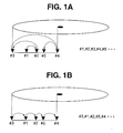
- a method referred to as a SCAN algorithm exists as a related technology for reducing the seek time that is one cause of overhead time.
- This method is an algorithm for carrying out processing where, as shown in FIG. 1A, when there is a plurality of "Input/Output" (hereinafter abbreviated to "I/O") requests (#1, #2, #3, #4, #5), these requests are sorted across the radial direction of the disc and replaced with the order (#3, #1, #2, #5, #4) as shown in FIG. 1B.
- I/O "Input/Output”
- FIG. 1A the coming and going of the head that is likely to occur when the I/O requests are processed in the order of arrival can be prevented and the respective seek times can therefore be reduced.
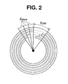
- FIG. 2 shows an example of arranging sub-blocks in the case where the skew and gap values are fixed.
- control can be exerted so that the head of the desired sub-block does not exceed the position of the head during the seek operation by making the skew value fixed. Therefore, when the desired sub-block is accessed, it is only necessary to wait for a rotation time that is the time for the head of this sub-block to return again to the head position so that the rotation wait time can therefore be reduced.
- FIG. 3 shows the overhead time for a disc arranged with sub-blocks as shown in FIG. 2.
- the horizontal axis shows the seek distance, i.e. the number of cylinders to be crossed over when the head for the disc is moved, and the vertical axis shows the time that this takes.
- the dotted-and-dashed line is the seek time T seek and the solid line is the overall overhead time.
- the overhead time is the sum of the seek time T seek and the rotation wait time T rd
- the difference between the solid line and the dotted-and-dashed line is therefore the rotation wait time T rd .
- the rotation wait time could not be estimated. Therefore, in the case where the maximum value for the overhead time is calculated, calculations can be performed for as shown by the dotted line in the graph, with this value being calculated as the time for one rotation. From this graph, by carrying out the arrangements of sub-blocks shown in FIG. 2, the overhead time can be kept small as shown by the solid line when compared with that described above shown by the dotted line.
- ZBR zone bit recording
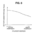
- FIG. 6 shows the relationship between the cylinder address and number of sectors per one track occurring at a disc storage device formatted using the ZBR method.
- the horizontal axis shows the cylinder address and the vertical axis shows the number of sectors per track, with inner tracks having fewer sectors than outer tracks.
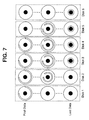
- n devices are selected from m disc storage devices and writing is carried out so as to fill these storage devices up in an order from the outer disc storage devices or from the inner disc storage devices.
- FIG. 7 shows an example of a case where the number of disc storage devices m is taken to be 6, the number of sub-blocks n into which the data is divided is taken to be 4, and sub-blocks are written in order from disc storage devices at the outer periphery.
- FIG. 8B is a graph showing transitions in the size of gaps for each sub-block when going from the outer periphery towards the inner periphery.
- the horizontal axis shows the track position and the vertical axis shows the size of the gap.
- the number of sectors per track becomes smaller when going from the outer periphery towards the inner periphery, with the gap value gradually becoming smaller in line with this gap value. Because of this, depending on the case it may not be possible for a sub-block to be fitted onto one track and a sub-block may therefore have to be put across two tracks, with the gap value therefore making a sudden jump from about 0 degrees to about 360 degrees.
- the time T r/w for actually reading or writing while the head for the disc is passing over the sub-block is small when the sub-blocks are arranged from the outer periphery but is large when the sub-blocks are arranged from the inner periphery, as shown in FIG. 8C.
- the horizontal axis shows the track position and the vertical axis shows the time necessary for reading or writing to and from each of the sub-blocks.
- the present invention sets out to resolve the aforementioned problems, it is the object of the present invention to provide a method and a device for controlling access to a disc storage device capable of providing gap and skew values for data that are constant for a plurality of the disc storage devices having a number of sectors per one track that is larger for tracks at the outer periphery than for tracks at the inner periphery even in the case of the arrangement of fixed length data.
- a method of controlling access to a disc storage device comprising a plurality of discs storing a plurality of second data obtained by dividing first data, each of a plurality of the discs being configured such that a number of sectors included at tracks in an outer section of the disc is greater than a number of sectors included at tracks in an inner section of the disc.
- the method comprises the step of deciding information and accessing the discs storage device.
- the step of accessing is for accessing the disc storage device on the basis of the decided information.
- a device for controlling access to a disc storage device comprising a plurality of discs storing a plurality of second data obtained by dividing first data, each of a plurality of the discs being configured such that a number of sectors included at tracks in an outer section of the discs is greater than a number of sectors included at tracks in an inner section of the disc.
- the device comprises a deciding unit and an accessing unit.
- the deciding unit is for deciding the discs storing each of a plurality of the second data and information comprising addresses of the second data stored on the discs and size of each of a plurality of the second data in such a manner that time required for accessing each of a plurality of the second data stored in the disc storage device becomes equal, the information being decided further on the basis of gaps expressed by angular differences between heads and ends of items of the second data when the second data is arranged on the tracks of the discs.
- the accessing unit is for accessing the disc storage device on the basis of the decided information.
- the overhead at the time of accessing data on a disc device can be reduced, the time required for reading and writing data can be fixed and input/output time can be easily estimated.
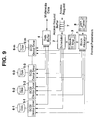
- FIG. 9 is a block diagram showing an example configuration of a multimedia server to which the device according to the present invention is applied for controlling access to the disc storage device.
- An arrangement part (Block Allocator) 1 makes a block map (Block Map) 3 to be described later based on inputted format parameters and data from a ZBR (zone bit recording) table (ZBR table) 8.
- the format parameters comprise a size S of one block of data, a number n by which the data is divided and a most appropriate skew value ( ⁇ skew ) etc.
- the ZBR table 8 is a table corresponding to the arrangement places of the data and a sector (Sector) number per one track (Track) at these places and is as shown in FIG. 6 when put in the form of a graph.
- the sector number for one track can then be investigated from the arrangement place of the data.
- a process is necessary for changing from physical sector addresses for disc storage devices (Disks) 6-1 to 6-m (storage means) to logical sector addresses and in this embodiment, this conversion is carried out by directly interrogating the disc storage devices 6-1 to 6-m via SCSI (ANSI Small Computer System Interface) drivers 5-1 to 5-m (reading means) to be described later.
- SCSI Small Computer System Interface
- the arrangement part 1 makes the block map 3 after deciding the arrangement of the data.
- the block map 3 is for showing where on the discs n sub-blocks obtained by dividing the kth data are stored, as shown in FIG. 10.
- the arrangement places for the sub-blocks are decided using the disc storage device number D ki , start logic sector address L ki on the disc storage device and number of sectors S ki comprising the sub-blocks.
- access requests for a plurality of data are generated and a number for data taken as information for identifying these requests, an address on the data buffer (Data Buffer) 4 on which the data is placed, and a flag displaying reading or writing are stored at an access request buffer (Access Request Buffer) 7.
- a scheduler (Scheduler) 2 reads this plurality of information from the access request buffer 7, refers to the block map 3 and investigates the arrangement places of the sub-blocks comprised by the requested data.
- the arrangement places comprise the disc storage device 6, the start logic sector address on the disc storage device 6, and the sector number, with the scheduler 2 carrying out an access request to the SCSI driver 5 driving the disc storage device 6. At this time, an access request for one disc storage device 6 is changed in order by the SCAN algorithm and issued.
- the data buffer 4 temporarily stores inputted multimedia data and multimedia data etc. read out from the disc storage device 6.
- an access request indicating writing to the disc storage device 6 for the multimedia data to be written to the disc storage device 6 is supplied to the access request buffer 7.
- the scheduler 2 then reads the access request from the access request buffer 7, calculates the address on the data buffer 4 at the time of reading multimedia data to be written to the disc storage device 6 from the data buffer 4 from the address of the data buffer 4 included in the access request and the sector number of the sub-block read out from the block map 3.
- This address is then supplied to the SCSI driver 5 together with a write instruction. This is to say that in what way multimedia is divided between a plurality of sub-blocks of different sizes can be decided.
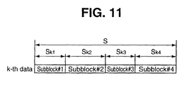
- FIG. 11 shows an example of dividing kth multimedia data between sub-blocks of different sizes.
- multimedia data of size S is divided between a sub-block #1 of size S k1 , a sub-block #2 of size S k2 , a sub-block #3 of size S k3 and a sub-block #4 of size S k4 .
- packet A0 is allotted to sub-block #1
- packet B0 is allotted to sub-block #2
- packet C0 is allotted to sub-block #3
- packet D4 is allotted to #4
- packet A1 being allotted to sub-block #1
- packet B1 being allotted to sub-block #2
- packet C1 being allotted to sub-block #3
- packet D4 being allotted to sub-block #4.
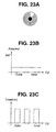
- FIG. 23 by allotting each packet in order to each of the sub-blocks, these are allotted to sub-block #1, sub-block #2, sub-block #3 and sub-block #4.
- the SCSI driver 5 reads the multimedia data from the data buffer 4 based on the address supplied by the scheduler 2 and writes each sub-block obtained by dividing the multimedia data to discs of prescribed disc storage devices 6. The sequence for the write operation is then complete as a result of this operation.
- an access request is stored in the access request buffer 7.
- the scheduler 2 then reads the access request from the access request buffer 7 and supplies this to the corresponding SCSI driver 5.
- the SCSI driver 5 then reads the sub-block designated by the access request from the corresponding disc storage device 6 based on the access request supplied by the scheduler 2.
- the address on the data buffer 4 made to store sub-blocks read-out from the disc storage device 6 is obtained by operations of the scheduler 2 based on an address obtained from the access request buffer 7 and the sector number of the sub-block obtained from the block map 3. This address is then supplied to the corresponding SCSI driver 5 together with a read instruction.
- the SCSI driver 5 therefore supplies the sub-block read from the disc storage device 6 to an address calculated by the scheduler 2 of the data buffer 4 to be stored. In this way, sub-blocks that have had their order substituted by the SCAN algorithm and have been read are arranged in the original order on the data buffer 4.
- Data requested by the data request can then be completed by gathering together sub-blocks placed at the data buffer 6, outputted by the data buffer 6 in the requested order, and the desired multimedia data can be outputted in order.
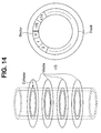
- the disc storage devices 6 can usually be accessed each region, with each region being referred to as a sector (Sector).
- a sector is usually from 512 bytes to about 4 kilobytes, with donut-shaped regions lined up along the circumference being referred to as tracks (Track) and regions of tracks present at equal distances from the center of a recording media (Media) having a plurality of overlaid layers gathered together into cylindrical shaped regions being referred to as cylinders (Cylinder).
- the physical address is then an address comprising the cylinder number, media number and sector number.
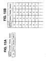
- the logical sector address (Logical Sector) L ki corresponds to a physical sector address comprising a cylinder number (Cylinder) CYL ki , a media number (Media) MED ki and a sector number (Sector) SEC ki , with a specific example of this being shown in FIG. 15B.
- a logical address can then be changed to a physical address, or a physical address can be changed to a logical address using this correspondence table.
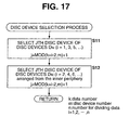
- n disc storage devices 6 for storing data are selected from a total of m disc storage devices 6.
- the data is divided so as to be taken as n sub-blocks, with these sub-blocks being divided into a group arranged from the outer periphery and a group arranged from the inner periphery.
- the numbers 1 to n are given to each of the sub-blocks, odd-numbered sub-blocks are arranged from the outer periphery and even-numbered sub-blocks are arranged from the inner periphery.
- the disc storage devices 6 on which the data is arranged are selected so as to be shifted so that sub-blocks do not accumulate around a small number of disc storage devices 6.
- MOD is an operator for calculating the remainder from dividing k + i - 2 by m (total number of disc storage devices).
- j MOD(k + i - 2, m) + 1
- MOD is the operator for calculating the remainder from dividing k + i - 2 by m.
- the sub-blocks are not concentrated around a small number of disc storage devices 6, it does not matter even if the jth disc storage device 6 expressed by equation (1) and equation (2) is not selected. For example, it is effective if a method is employed where disc storage devices 6 that do not use the outer periphery very much are selected with regards to the disc storage devices arranging sub-blocks from the outer periphery and disc storage devices 6 that do not use the inner periphery a great deal are selected with regards to disc storage devices arranging sub-blocks from the inner periphery.
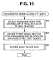
- the disc storage device 6 is decided and step S2 of FIG. 16 is then proceeded to.
- step S2 start logic sectors that arrange sub-blocks are decided for each of the selected disc storage devices 6.
- FIG. 18 is a flowchart showing the processing sequence for deciding these start logic sectors.
- FIG. 19 is a flowchart showing the details of the process occurring in step S21 of FIG. 18.
- step S31 the outermost track within a region for which sub-blocks have not yet been arranged is selected as a track for arranging sub-blocks.
- the cylinder number (CYL ki ) of the physical sector address and the media number (MED ki ) are decided, the ZBR table 8 is referred to, and the sector numbers (T ki ) per each one track occurring at the arrangement places can be understood.
- step S32 the angle ⁇ ki between the head of the track selected in step S31 and the head of the outermost track is obtained from the cylinder number (CYL ki ) and the most appropriate skew ( ⁇ skew ) value using equation (3).
- ⁇ ki ⁇ skew x CYL ki
- step S33 is proceeded to and the sector number (SEC ki ) is obtained using equation (4) from the angle ⁇ ki obtained in equation (3) and the sector number (T ki ) per track.
- SEC ki T ki x ⁇ ki /360
- step S34 a logical sector address (L ki ) is decided from the physical sector address (CYL ki , MED ki , SEC ki ) obtained in steps S31 to S33 and the process returns.
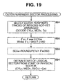
- FIG. 20 is a flowchart showing the details of the process occurring in step S22 of FIG. 18.
- step S41 the innermost track from the center of the not-yet arranged region is selected as the track to which sub-blocks are to be arranged.
- the cylinder number (CYL ki ) of the physical sector address and media number (MED ki ) are decided, the ZBR table is referred to and the sector numbers (T ki ) per each one track occurring at this arrangement position can be known.
- step S42 the angle ⁇ ki between the head of the track selected in step S41 and the head of the outermost track is obtained, with the sector number (SEC ki ) then being obtained in step S43.
- step S44 the logical sector address (L ki ) is decided from the obtained physical sector address (CYL ki , MED ki , SEC ki ).
- tracks to be arranged with sub-tracks are selected from the outermost track within yet to be arranged regions when sub-blocks are arranged from tracks of the outer periphery and tracks to be arranged with sub-blocks are selected from the innermost tracks within regions yet to be arranged when sub-blocks are arranged at tracks from the inner periphery, but it is not always necessary to select the outermost track or innermost track.
- the zone is the same, the sector number per track is the same and the size of each sub-block and gap value therefore do not change.
- step S3 of FIG. 16 is proceeded to and the size of each sub-block is decided.
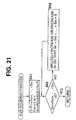
- the processing sequence for deciding the sizes of the sub-blocks is described later with reference to the flowchart of FIG. 21.
- step S51 the sum T of the sector numbers T ki per track of the tracks corresponding to the arrangement place for the sub-blocks to be arranged is obtained.
- step S51 the sum T of the sector numbers T ki per track of the tracks corresponding to the arrangement place for the sub-blocks to be arranged is obtained.
- step S52 is proceeded to and a determination is made as to whether or not the sum of the sizes S ki for each sub-block obtained in step S51 is equal to the size S of the original data by carrying out calculation expressed by the above equation (5).
- step S53 is proceeded to and the size S ki of each sub-block is increased or decreased slightly so that the sum of the size S ki of each sub-block becomes equal to the size S of the original data.
- Step S52 is then returned to, with the process of step S52 and S53 then being repeated until it is determined that the sum of the sizes S ki of each of the sub-blocks is equal to the size S of the original data.
- step S52 when it is determined in step S52 that the sum of the sizes S ki of each of the sub-blocks is equal to the size S of the original data, the process ends and then returns. In this way, the process of step S3 of the flowchart shown in FIG. 16 is complete, with all of the processing therefore being complete.
- FIG. 22 shows an example of the disc storage devices 6 divided into sub-blocks.
- the number of disc storage devices 6 is taken to be 6 and the number of sub-blocks is taken to be 4.
- the first item of data is the arranged so as to be divided between disc storage devices 6-1 to 6-4.
- the sub-blocks arranged at the disc storage devices 6-1 and 6-3 are introduced to the outermost track and the sub-blocks arranged at disc storage devices 6-2 and 6-4 are introduced to the innermost tracks.
- the second item of data is introduced to the disc storage devices 6-2 to 6-5 in the order of outer, inner, outer, inner
- the third item of data is introduced to the disc storage devices 6-3 to 6-6 in the order of outer, inner, outer, inner.
- Data is then provided similarly thereafter, with, for example, the final data then being arranged in more or less the middle of the cylinder of disc storage devices 6-3 to 6-6.
- a method of constructing a VOD (Video on Demand) server for the case of using a ZBR formatted disc storage device is disclosed in US Patent No. 5,510,905.
- data of the same size obtained by dividing an image data stream is arranged so as to be divided between two pairs of tracks, with the data transmission rate at the time of playback being kept almost fixed by dividing the sizes occurring at each respective track in proportion to the number of sector numbers per track.
- the above embodiment is a data arrangement method for resolving the above problems by shortening the rotation wait time even for ZBR formatted disc storage devices, which is different from the problems resolved by US Patent No. 5,510,905. Further, whereas in US Patent No. 5,510,905 the tracks at which data was provided was limited to two pairs, in the above embodiment, a method of configuring a flexible system is provided that is capable of arranging data to more than two pairs of tracks if necessary.
- the skew and gaps for sub-blocks on the same disc storage devices 6 can be fixed values. It is therefore possible to reduce the overhead time for the disc storage device i.e. the sum of the seek time and the rotation wait time by using this in combination with the SCAN algorithm.
- the time for actually reading or writing to a sub-block while the heads of the disc storage devices 6 are passing over the tracks on which the sub-blocks are stored also becomes uniform for each sub-block and it therefore becomes easy to estimate the overall maximum value of the I/O time. Further, this estimated maximum value is also smaller and more reliable than that of the related art.
- control or reading and writing of data to or from the disc storage device 6 is executed using a dedicated controller but control of reading and writing of data to and from the disc storage device 6 can also be carried out by causing control software for these controllers to operate at a CPU such as a host computer etc.
- scanning was carried out in a direction from the outer periphery to the inner periphery when data was accessed but scanning from the inner periphery to the outer periphery is also possible.
- the most appropriate skew at the time of accessing data is set while the head is being moved from the inner periphery to the outer periphery.
- a hard disc was used as a medium for recording data but other recording media such as an optical disc or magnet-optical disc etc. can also be used.
Applications Claiming Priority (2)
| Application Number | Priority Date | Filing Date | Title |
|---|---|---|---|
| JP26421696 | 1996-10-04 | ||
| JP264216/96 | 1996-10-04 |
Publications (1)
| Publication Number | Publication Date |
|---|---|
| EP0834878A2 true EP0834878A2 (fr) | 1998-04-08 |
Family
ID=17400114
Family Applications (1)
| Application Number | Title | Priority Date | Filing Date |
|---|---|---|---|
| EP97116990A Withdrawn EP0834878A2 (fr) | 1996-10-04 | 1997-09-30 | Méthode et dispositif pour contrÔler l'accès à un dispositif de stockage à disque |
Country Status (2)
| Country | Link |
|---|---|
| US (1) | US6223249B1 (fr) |
| EP (1) | EP0834878A2 (fr) |
Cited By (2)
| Publication number | Priority date | Publication date | Assignee | Title |
|---|---|---|---|---|
| EP0905693A1 (fr) * | 1997-04-07 | 1999-03-31 | Sony Corporation | Dispositif et procede d'enregistrement de donnees et dispositif et procede de commande de pile de disques |
| WO2015085313A1 (fr) | 2013-12-06 | 2015-06-11 | Concurrent Ventures, LLC | Système et procédé de répartition dynamique de charge entre dispositifs à supports de stockage sur la base d'un niveau médian de performance |
Families Citing this family (11)
| Publication number | Priority date | Publication date | Assignee | Title |
|---|---|---|---|---|
| US20020199017A1 (en) * | 2001-06-25 | 2002-12-26 | Russell Lance W. | Routing meta data for network file access |
| JP4651913B2 (ja) * | 2003-02-17 | 2011-03-16 | 株式会社日立製作所 | 記憶装置システム |
| JP4060235B2 (ja) | 2003-05-22 | 2008-03-12 | 株式会社日立製作所 | ディスクアレイ装置及びディスクアレイ装置の制御方法 |
| JP2004348464A (ja) * | 2003-05-22 | 2004-12-09 | Hitachi Ltd | ストレージ装置、及び通信信号の整形回路 |
| JP4156499B2 (ja) * | 2003-11-28 | 2008-09-24 | 株式会社日立製作所 | ディスクアレイ装置 |
| JP4497918B2 (ja) * | 2003-12-25 | 2010-07-07 | 株式会社日立製作所 | ストレージシステム |
| JP4634049B2 (ja) | 2004-02-04 | 2011-02-16 | 株式会社日立製作所 | ディスクアレイ装置における異常通知制御 |
| US8066515B2 (en) * | 2004-11-17 | 2011-11-29 | Nvidia Corporation | Multiple graphics adapter connection systems |
| US8539176B2 (en) * | 2008-07-08 | 2013-09-17 | HGST Netherlands B.V. | Data storage devices accepting queued commands having deadlines |
| US8407440B2 (en) * | 2008-07-08 | 2013-03-26 | HGST Netherlands B.V. | Techniques for scheduling requests for accessing storage devices using sliding windows |
| CN113687793B (zh) * | 2017-06-30 | 2024-03-15 | 伊姆西Ip控股有限责任公司 | 存储管理方法和系统 |
Family Cites Families (5)
| Publication number | Priority date | Publication date | Assignee | Title |
|---|---|---|---|---|
| US5202979A (en) | 1985-05-08 | 1993-04-13 | Thinking Machines Corporation | Storage system using multiple independently mechanically-driven storage units |
| US4899342A (en) | 1988-02-01 | 1990-02-06 | Thinking Machines Corporation | Method and apparatus for operating multi-unit array of memories |
| KR940022276A (ko) | 1993-03-11 | 1994-10-20 | 오오가 노리오 | 병렬연산 처리장치 |
| US5774714A (en) * | 1995-03-27 | 1998-06-30 | Hewlett-Packard Company | Zone bit recording enhanced video data layout |
| TW332284B (en) | 1995-10-30 | 1998-05-21 | Sony Co Ltd | Method and apparatus for controlling access to a recording disk |
-
1997
- 1997-09-30 EP EP97116990A patent/EP0834878A2/fr not_active Withdrawn
- 1997-10-02 US US08/944,093 patent/US6223249B1/en not_active Expired - Lifetime
Cited By (6)
| Publication number | Priority date | Publication date | Assignee | Title |
|---|---|---|---|---|
| EP0905693A1 (fr) * | 1997-04-07 | 1999-03-31 | Sony Corporation | Dispositif et procede d'enregistrement de donnees et dispositif et procede de commande de pile de disques |
| EP0905693A4 (fr) * | 1997-04-07 | 2001-02-14 | Sony Corp | Dispositif et procede d'enregistrement de donnees et dispositif et procede de commande de pile de disques |
| WO2015085313A1 (fr) | 2013-12-06 | 2015-06-11 | Concurrent Ventures, LLC | Système et procédé de répartition dynamique de charge entre dispositifs à supports de stockage sur la base d'un niveau médian de performance |
| CN105981351A (zh) * | 2013-12-06 | 2016-09-28 | 并发投资有限责任公司 | 基于中等范围性能水平来动态负荷平衡存储介质装置的系统和方法 |
| EP3078184A4 (fr) * | 2013-12-06 | 2017-07-26 | Concurrent Ventures LLC | Système et procédé de répartition dynamique de charge entre dispositifs à supports de stockage sur la base d'un niveau médian de performance |
| CN105981351B (zh) * | 2013-12-06 | 2019-08-02 | 并发投资有限责任公司 | 动态负荷平衡存储介质装置的系统和方法 |
Also Published As
| Publication number | Publication date |
|---|---|
| US6223249B1 (en) | 2001-04-24 |
Similar Documents
| Publication | Publication Date | Title |
|---|---|---|
| US6499083B1 (en) | Disk-based storage system responsive to a direction-selection signal for autonomously controlling seeks in a sequence determined by the direction-selection signal and a locally-stored doubly linked list | |
| JP4279515B2 (ja) | 記録再生装置 | |
| US6496460B2 (en) | Optical disk, an optical disk device, and a method of managing defects in an optical disk | |
| JP3373690B2 (ja) | ディスク状記録媒体及びディスク装置 | |
| EP0834878A2 (fr) | Méthode et dispositif pour contrÔler l'accès à un dispositif de stockage à disque | |
| JP2682791B2 (ja) | 異なる線密度で記録するデータ記憶装置およびその方法 | |
| JP2005516329A (ja) | データ記憶装置及びデータ記憶装置を扱う方法 | |
| US5274507A (en) | Parallel data encoding for moving media | |
| US20020110070A1 (en) | High speed data recording and/or reproducing method and apparatus with increased sector access speed | |
| US6639746B1 (en) | Method and apparatus for recording/reproducing multi-channel data | |
| JP3637346B1 (ja) | 情報記録装置と情報記録方法とプログラム | |
| JP3255887B2 (ja) | 磁気ディスク装置およびそのディスクアクセス方法 | |
| JP3809674B2 (ja) | ディスク制御方法および装置 | |
| JP3865163B2 (ja) | ディスク制御方法および装置 | |
| JP3510747B2 (ja) | 論理フォーマットを有する記録媒体、記録再生装置、論理フォーマット装置及び論理フォーマット形成方法 | |
| JP2005129168A (ja) | 情報記録装置と情報記録方法とプログラム | |
| JP4419211B2 (ja) | 記録媒体制御装置及び記録媒体制御方法 | |
| US20050078949A1 (en) | Reproducing apparatus and method, and recording apparatus and method | |
| JP2834081B2 (ja) | 磁気ディスク制御装置 | |
| JPH09190294A (ja) | 連続情報記録再生装置 | |
| JPH03260955A (ja) | ディスクシステムにおけるスキップ処理方法 | |
| JP2000099275A (ja) | ディスクアレイ制御方法及びディスクアレイ装置 | |
| JPH03183069A (ja) | 光磁気ディスクデータ転送方法 | |
| JPH10161819A (ja) | ディスクアレイ制御方法および装置 | |
| JP2008010109A (ja) | データ記憶装置 |
Legal Events
| Date | Code | Title | Description |
|---|---|---|---|
| PUAI | Public reference made under article 153(3) epc to a published international application that has entered the european phase |
Free format text: ORIGINAL CODE: 0009012 |
|
| AK | Designated contracting states |
Kind code of ref document: A2 Designated state(s): AT BE CH DE DK ES FI FR GB GR IE IT LI LU MC NL PT SE |
|
| RAP1 | Party data changed (applicant data changed or rights of an application transferred) |
Owner name: SONY CORPORATION |
|
| STAA | Information on the status of an ep patent application or granted ep patent |
Free format text: STATUS: THE APPLICATION HAS BEEN WITHDRAWN |
|
| 18W | Application withdrawn |
Withdrawal date: 20021014 |