EP0834460B1 - Sheet material collating system - Google Patents
Sheet material collating system Download PDFInfo
- Publication number
- EP0834460B1 EP0834460B1 EP97116583A EP97116583A EP0834460B1 EP 0834460 B1 EP0834460 B1 EP 0834460B1 EP 97116583 A EP97116583 A EP 97116583A EP 97116583 A EP97116583 A EP 97116583A EP 0834460 B1 EP0834460 B1 EP 0834460B1
- Authority
- EP
- European Patent Office
- Prior art keywords
- carriers
- guide rail
- rail
- drive
- rollers
- Prior art date
- Legal status (The legal status is an assumption and is not a legal conclusion. Google has not performed a legal analysis and makes no representation as to the accuracy of the status listed.)
- Expired - Lifetime
Links
- 239000000463 material Substances 0.000 title claims description 18
- 239000000969 carrier Substances 0.000 claims description 44
- 239000004033 plastic Substances 0.000 claims description 3
- 229920003023 plastic Polymers 0.000 claims description 3
- 239000002184 metal Substances 0.000 claims 1
- 238000005096 rolling process Methods 0.000 description 5
- 238000010276 construction Methods 0.000 description 3
- 230000007246 mechanism Effects 0.000 description 3
- XAGFODPZIPBFFR-UHFFFAOYSA-N aluminium Chemical compound [Al] XAGFODPZIPBFFR-UHFFFAOYSA-N 0.000 description 2
- 229910052782 aluminium Inorganic materials 0.000 description 2
- 238000000034 method Methods 0.000 description 2
- 239000004677 Nylon Substances 0.000 description 1
- 229920002292 Nylon 6 Polymers 0.000 description 1
- 229910000831 Steel Inorganic materials 0.000 description 1
- 239000002131 composite material Substances 0.000 description 1
- 229920006351 engineering plastic Polymers 0.000 description 1
- 239000011152 fibreglass Substances 0.000 description 1
- 239000011521 glass Substances 0.000 description 1
- 239000003562 lightweight material Substances 0.000 description 1
- 229920001778 nylon Polymers 0.000 description 1
- 230000037361 pathway Effects 0.000 description 1
- 229920002635 polyurethane Polymers 0.000 description 1
- 239000004814 polyurethane Substances 0.000 description 1
- 239000012858 resilient material Substances 0.000 description 1
- 239000010959 steel Substances 0.000 description 1
Images


Classifications
-
- B—PERFORMING OPERATIONS; TRANSPORTING
- B65—CONVEYING; PACKING; STORING; HANDLING THIN OR FILAMENTARY MATERIAL
- B65H—HANDLING THIN OR FILAMENTARY MATERIAL, e.g. SHEETS, WEBS, CABLES
- B65H39/00—Associating, collating, or gathering articles or webs
- B65H39/02—Associating,collating or gathering articles from several sources
Definitions
- the present invention relates to a sheet material handling apparatus.
- the present invention relates to an apparatus for carrying sheet material handling devices, such as pockets or saddles for signatures, in a collating system.
- a known sheet material collating system includes a plurality of pockets which are supported for movement on a conveyor chain past a plurality of signature feed mechanisms. Each one of the signature feed mechanisms deposits a signature into a pocket travelling underneath the feed mechanism. In this manner, collated assemblages of signatures are formed in the pockets. The pockets are subsequently opened to allow the collated assemblages of signatures to drop out of the pockets for further handling.
- EP 0 112 471 A1 which discloses the features of the preamble of claim 1, describes a device for moving a multiplicity of conveyor container pockets about an endless pathway in a conveyor which includes support housing where a pocket is fixed on one of its sides to the housing.
- EP 0 656 304 A2 describes an arrangement for transporting articles along a closed path.
- the arrangement comprises at least one transport module moving along two parallel rails.
- the module comprises a bracket fixedly mounted to the module in order to drive the module, a driving chain is fixedly mounted to the bracket.
- the present invention is a sheet material handling apparatus comprising an elongate guide rail, a plurality of interconnected carriers supported on a first side of the guide rail for movement in a first direction along the guide rail, and a plurality of sheet material receivers for receiving and supporting sheet material.
- Each one of the receivers is connected with and movable with a respective one of the carriers.
- the carriers are disposed intermediate the receivers and the guide rail.
- the receivers are cantilevered out from the guide rail in a second direction transverse to the first direction.
- each one of the carriers has a drive surface.
- the apparatus comprises drive means including a drive member engageable with the drive surfaces on the carriers for moving the carriers and thereby the receivers in the first direction along the guide rail.
- the present invention relates to a sheet material handling apparatus.
- the present invention relates to a collating system for sheet material such as signatures.
- Fig. 1 illustrates a sheet material collating system 10.
- the collating system 10 includes upper and lower guide rails 12 and 14 (Figs. 2 and 5).
- the collating system 10 also includes a plurality of carriers 20 which are interconnected and supported for movement along the rails 12 and 14, and one or more drive units 30 for driving the carriers along the rails.
- a plurality of sheet material receivers, such as pockets 40 for holding sheet material, such as signatures, are supported on the carriers 20 for movement with the carriers along the rails 12 and 14.
- the guide rails 12 and 14 are preferably made from tubular steel having a cylindrical cross-sectional configuration.
- the guide rails 12 and 14 have cylindrical outer surfaces 12a and 14a, respectively.
- the guide rails 12 and 14 extend parallel to each other at a fixed, predetermined distance from each other.
- the guide rails 12 and 14 are shown in the drawings as extending in a single plane in a closed, oval-shaped loop 16, it should be understood that the rails could extend in more than one plane and/or could extend in other configurations.
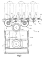
- the drive units 30 (Fig. 1) are located adjacent to the guide rails 12 and 14. A sufficient number of drive units 30 are provided to ensure proper movement of the interconnected carriers 20 along the rails 12 and 14. The drive units 30 are placed at desired locations along the loop 16. In the illustrated embodiment, two identical drive units 30 are spaced apart on opposite sides of the loop 16.
- Each drive unit 30 (Fig. 3) includes a frame 42 which is fixed in position adjacent to the rails 12 and 14.
- An electric motor 44 is mounted on the frame 42.
- the electric motor 44 transmits power through a gearbox 45 and a flexible drive member 46, such as a V-belt or chain, to an externally toothed drive wheel 48.
- Each drive unit 30 includes an externally toothed drive belt 50 (Fig. 3) which extends in a closed loop configuration around two pulleys 52 and 54. On one side of the closed loop configuration the drive belt 50 engages and is driven by the drive wheel 48. On the other side of the closed loop configuration the drive belt 50 is engageable with the carriers 20, in a manner described below, to drive the carriers, and thus the pockets 40, along the rails 12 and 14.
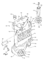
- Each carrier 20 (Fig. 4) includes a carrier body 60.
- the carrier body 60 is preferably made as one piece from an engineering plastic composite material, such as glass fiber reinforced plastic, such as nylon 6/6 with 50% long glass.
- the carrier body 60 has a generally planar, box-shaped overall configuration including opposite inner and outer major side surfaces 62 and 64 and opposite upper and lower portions 66 and 68.
- the carrier body 60 also has opposite first and second end portions 70 and 72.
- a series of drive teeth 74 are formed on the carrier body 60. Each one of the drive teeth 74 extends vertically along the inner major side surface 62 of the carrier body 60. The drive teeth 74 are spaced along the length of the carrier body 60, between the first and second end portions 70 and 72 of the carrier body.
- a pair of upper pocket mounting openings 76 are formed in the upper end portion 66 of the carrier body 60.
- a pair of lower pocket mounting openings 78 are formed in the lower end portion 68 of the carrier body 60.
- An upper carrier wheel insert 80 (Fig. 4) is insert molded in the first end portion 70 of the carrier body 60, at a location above the drive teeth 74.
- the carrier wheel insert 80 is made from a material such as aluminum.
- the carrier wheel insert 80 has an internally threaded end portion 82 which projects from the carrier body 60. The end portion 82 extends at an angle of 45° relative to a base plane 84 of the carrier body 60.
- An upper drive side guide roller 90 is supported for rotation on the carrier wheel insert 80.
- the roller 90 is molded from a resilient material, such as polyurethane, and has a concave outer rolling surface 92.
- a sealed ball bearing (not shown) is molded into the roller 90.
- the roller 90 is fixed for movement with the outer race of the bearing.
- a bolt 94 is threaded into the end portion 82 of the carrier wheel insert 80.
- the bolt 94 and a pair of washers 96 secure the inner race of the bearing to the insert 80.
- the upper drive side guide roller 90 is thereby journalled for rotation relative to the carrier body 60.
- a lower carrier wheel insert 100 (Figs. 2 and 4) is insert molded in the first end portion 70 of the carrier body 60.
- the lower carrier wheel insert 100 is disposed below the drive teeth 74 and directly below the upper carrier wheel insert 80.
- the lower carrier wheel insert 100 is identical in construction to the upper carrier wheel insert 80.
- a lower drive side guide roller 110 is supported for rotation on the lower carrier wheel insert 100.
- the lower drive side guide roller 110 is identical in construction to the upper drive side guide roller 90 and has a concave outer rolling surface 112.
- a sealed ball bearing (not shown) is molded within the roller 110.
- the roller 110 is rotatably secured in position on the insert 100, and thereby on the carrier body 60, by a bolt 114.
- a pivot support pin 120 (Fig. 4) is insert molded in the second end portion 72 of the carrier body 60.
- the pivot pin 120 is made from a material such as aluminum.
- the pivot pin 120 has internally threaded upper and lower end portions 122 and 124 which project from the carrier body 60.
- the end portions 122 and 124 of the pivot pin 120 extend in a vertical orientation parallel to the base plane of the carrier body 60.
- An upper pocket side guide roller 130 is supported for rotation about the upper end portion 122 of the pivot pin 120.
- the upper pocket side guide roller 130 is identical in construction to the drive side guide rollers 90 and 110 and has a concave outer rolling surface 132.
- a sealed ball bearing (not shown) is molded within the upper pocket side guide roller 130.
- the upper pocket side guide roller 130 In assembly of the carrier 20, the upper pocket side guide roller 130 is placed over the projecting upper end portion 122 of the pivot pin 120. The inner race of the bearing in the upper pocket side guide roller 130 rests on a shoulder 134 on the carrier body 60. The upper pocket side guide roller 130 is secured in position relative to the carrier body 60 when the carrier 20 is connected with another carrier.
- This interconnection process can be described with reference to Figs. 4 and 5 in regards to interconnecting the identical carriers 20 (Figs. 4 and 5) and 20a (Fig. 5).
- a nylon bearing 140 is inserted into the upper end of a cylindrical passage 142 in the carrier 20a.
- the bearing 140 is keyed to the carrier body 60 of the carrier 20a to prevent rotation of the bearing in the passage.
- the carrier 20 is then moved to a position adjacent to the carrier 20a in which the passage 142 in the carrier 20a is aligned with the pivot pin 120 of the carrier 20.
- a tubular connecting stud 144 is inserted through the bearing 140 and through the passage 142 in the carrier 20a.
- the connecting stud 144 is smaller in diameter than the bearing 140 in the passage 142 in the carrier 20a.
- the connecting stud 144 bottoms out on the inner race of the bearing in the upper pocket side guide roller 130.
- An externally threaded bolt 146 is inserted through the connecting stud 144, and through the open center of the bearing in the upper pocket side guide roller 130.
- the bolt 146 is screwed into the upper end portion 122 of the pivot pin 120 with the head of the bolt engaging an internal shoulder (not shown) on the connecting stud 44.
- the bolt 146 secures the connecting stud 144 to the pivot pin 120 and, thereby, to the carrier body 60 of the carrier 20.
- the inner race of the bearing in the roller 130 is captured between the connecting stud 144 and the carrier body 60 of the carrier 20.
- a retaining ring 148 on the connecting stud 144 limits vertical movement of the parts.
- the upper pocket side guide roller 130 which is fixed to the outer race of its internal bearing, is thus supported for rotation about the connecting stud 144.
- the connecting stud 144 which is fixed for movement with the carrier 20, is freely rotatable within the bearing 140 in the carrier 20a.
- the axis of rotation of the upper side guide roller 130 is not parallel to the axis of rotation of the upper drive side guide roller 90.
- a lower pocket side guide roller 150 is secured in position between the carrier 20 and the adjacent carrier 20a, by a lower connecting stud 152.
- the axis of rotation of the lower pocket side guide roller 150 is parallel to and co-extensive with the axis of rotation of the upper pocket side guide roller 130, and is not parallel to the axis of rotation of the lower drive side guide roller 110.
- the carriers 20 and 20a are thus interconnected for movement along the rails 12 and 14.
- the pivot pin 120 defines a pivot axis 154 about which the carrier 20 is pivotable relative to the carrier 20a to enable movement of the interconnected carriers around curves in the loop 16.
- the pocket side guide rollers 130 and 150 are rotatable about the pivot axis 154.
- a desired number of carriers 20 are interconnected in this manner and are mounted on the upper and lower guide rails 12 and 14 as described below.
- each upper drive side guide roller 90 (Fig. 2) is disposed above, and inward of (that is, in a direction toward the drive unit 30), the upper guide rail 12.
- the concave surface 92 of each upper drive side guide roller 90 engages the convex outer surface 12a of the upper guide rail 12.
- Each lower drive side guide roller 110 is disposed below, and inward of (that is, in a direction toward the drive unit) the lower guide rail 14.
- the concave surface 112 of each lower drive side guide roller 110 engages the convex outer surface 14a of the lower guide rail 14.
- Each upper pocket side guide roller 130 is disposed above, and outward of (that is, in a direction toward the pocket 40) the upper guide rail 12.
- the concave surface 132 of each upper pocket side guide roller 130 engages the convex outer surface 12a of the upper guide rail 12.
- Each lower pocket side guide roller 150 is disposed below, and outward of (that is, in a direction toward the pocket 40) the lower guide rail 14.
- the concave outer surface of each lower pocket side guide roller 150 engages the convex outer surface 14a of the lower guide rail 14.
- Each one of the carriers 20 is thus supported by four rollers 90, 110, 130 and 150 for rolling movement along the upper and lower rails 12 and 14.
- the train of interconnected carriers 20 is supported for rolling movement along the loop 16.
- Each pocket 40 is made from light weight material such as plastic and has an upper mounting portion, indicated schematically at 160, which is engageable in the upper mounting slots 76 in a respective carrier body 60.
- Each pocket 40 has a lower mounting portion, indicated schematically at 162, which is engageable in the lower mounting slots 78 in a respective carrier body 60.
- the lower mounting portion 162 of the pocket 40 is spring loaded to enable easy on-off movement of the pocket relative to the carrier 20.
- a handle portion 164 on the pocket 40 facilitates removal of the pocket from the carrier 20.
- each pocket 40 is supported only at its right-hand side, on a respective carrier 20, and projects in a direction to the left as viewed in Fig. 2.
- the pockets 40 project from the carriers 20 in a direction away from the drive unit 30.
- the drive belt 50 on the drive unit engages the drive teeth 74 on the carriers.
- the drive belt 50 drives the carriers 20, and thus the pockets 40, along the rails 12 and 14.
- devices other than pockets can be mounted on the carriers 20.
- saddles for receiving folded signatures oriented with their folded edges upward can be mounted on the carriers 20.
Landscapes
- Collation Of Sheets And Webs (AREA)
- Handcart (AREA)
- Pile Receivers (AREA)
- Toys (AREA)
Applications Claiming Priority (2)
| Application Number | Priority Date | Filing Date | Title |
|---|---|---|---|
| US08/719,997 US5709375A (en) | 1996-09-25 | 1996-09-25 | Sheet material collating system |
| US719997 | 1996-09-25 |
Publications (3)
| Publication Number | Publication Date |
|---|---|
| EP0834460A2 EP0834460A2 (en) | 1998-04-08 |
| EP0834460A3 EP0834460A3 (en) | 1998-08-05 |
| EP0834460B1 true EP0834460B1 (en) | 2003-05-07 |
Family
ID=24892243
Family Applications (1)
| Application Number | Title | Priority Date | Filing Date |
|---|---|---|---|
| EP97116583A Expired - Lifetime EP0834460B1 (en) | 1996-09-25 | 1997-09-24 | Sheet material collating system |
Country Status (6)
| Country | Link |
|---|---|
| US (1) | US5709375A (https=) |
| EP (1) | EP0834460B1 (https=) |
| JP (1) | JP4031850B2 (https=) |
| CN (1) | CN1064636C (https=) |
| CZ (1) | CZ292697A3 (https=) |
| DE (1) | DE69721680T2 (https=) |
Families Citing this family (7)
| Publication number | Priority date | Publication date | Assignee | Title |
|---|---|---|---|---|
| EP1911532B1 (en) * | 2004-06-30 | 2012-02-29 | NEC Corporation | Transporter / sorter and transport box |
| DE502005007197D1 (de) † | 2005-09-12 | 2009-06-10 | Mueller Martini Holding Ag | Einrichtung für das Zusammentragen bzw. Sammeln von Druckprodukten |
| DE102010063741A1 (de) | 2010-12-21 | 2012-06-21 | Robert Bosch Gmbh | Transporteinrichtung |
| CN102491125A (zh) * | 2011-11-22 | 2012-06-13 | 中国二十二冶集团有限公司 | 自由调整外设轨道型缠绕机器人装置 |
| DE102012104539B4 (de) * | 2012-05-25 | 2015-08-27 | Askion Gmbh | Modulares Zustellsystem |
| DE102017205868A1 (de) * | 2016-05-09 | 2017-11-09 | Heidelberger Druckmaschinen Ag | Transportsystem für bogenförmige Elemente |
| CN107902500A (zh) * | 2017-11-27 | 2018-04-13 | 二十二冶集团精密锻造有限公司 | 外置轨道的卫星式缠绕方法 |
Family Cites Families (15)
| Publication number | Priority date | Publication date | Assignee | Title |
|---|---|---|---|---|
| US778637A (en) * | 1904-06-14 | 1904-12-27 | Cottrell C B & Sons Co | Machine for folding paper or other fabrics. |
| US3711083A (en) * | 1971-03-03 | 1973-01-16 | R Cantrell | Newspaper inserting machine |
| CH594553A5 (https=) * | 1976-02-19 | 1978-01-13 | Grapha Holding Ag | |
| US4496141A (en) * | 1982-12-17 | 1985-01-29 | Rockwell International Corporation | Method and apparatus for opening folded newspapers |
| CA1197487A (en) * | 1982-12-17 | 1985-12-03 | George M. Statkus | Device for moving conveyor containers |
| DE3408963A1 (de) * | 1984-03-12 | 1985-09-19 | Liebherr-Verzahntechnik Gmbh, 8960 Kempten | Transportvorrichtung zum foerdern von traegern |
| US4555101A (en) * | 1984-03-13 | 1985-11-26 | Stobb, Inc. | Method and apparatus for separating signatures from a stack |
| US4723770A (en) * | 1986-06-20 | 1988-02-09 | Graphic Management Associates, Inc. | Straight-line insert machine |
| DE3633702A1 (de) * | 1986-10-03 | 1988-04-14 | Otmar Fahrion | Foerdereinrichtung |
| US4971189A (en) * | 1988-02-01 | 1990-11-20 | Hunter Industries | Multi-station assembly apparatus |
| FR2638694B1 (fr) * | 1988-11-10 | 1991-08-02 | Ism Equipements Indls Montage | Installation de transfert comportant un circuit ferme de rails |
| DE3914763A1 (de) * | 1989-05-05 | 1990-12-06 | Duerkopp Adler Ag | Stationaere antriebsvorrichtung in einem schleppkreisfoerderer |
| ES2065101T3 (es) * | 1991-04-26 | 1995-02-01 | Ferag Ag | Procedimiento y dispositivo para confeccionar productos de imprenta. |
| US5299680A (en) * | 1992-12-04 | 1994-04-05 | Rhodes Arthur B | Conveyor system with transverse pusher to transfer load carrying units between separate conveying paths |
| IT1265244B1 (it) * | 1993-12-01 | 1996-10-31 | Alcatel Italia | Dispositivo per il trasporto di oggetti lungo un percorso chiuso a guida |
-
1996
- 1996-09-25 US US08/719,997 patent/US5709375A/en not_active Expired - Lifetime
-
1997
- 1997-09-17 CZ CZ972926A patent/CZ292697A3/cs unknown
- 1997-09-22 CN CN97116560A patent/CN1064636C/zh not_active Expired - Fee Related
- 1997-09-24 DE DE69721680T patent/DE69721680T2/de not_active Expired - Lifetime
- 1997-09-24 EP EP97116583A patent/EP0834460B1/en not_active Expired - Lifetime
- 1997-09-25 JP JP26001397A patent/JP4031850B2/ja not_active Expired - Fee Related
Also Published As
| Publication number | Publication date |
|---|---|
| JPH10109813A (ja) | 1998-04-28 |
| US5709375A (en) | 1998-01-20 |
| CN1177564A (zh) | 1998-04-01 |
| DE69721680D1 (de) | 2003-06-12 |
| CN1064636C (zh) | 2001-04-18 |
| DE69721680T2 (de) | 2004-04-08 |
| JP4031850B2 (ja) | 2008-01-09 |
| EP0834460A3 (en) | 1998-08-05 |
| EP0834460A2 (en) | 1998-04-08 |
| HK1009116A1 (en) | 1999-05-28 |
| CZ292697A3 (cs) | 1998-05-13 |
Similar Documents
| Publication | Publication Date | Title |
|---|---|---|
| US6612420B1 (en) | Device for transferring articles between oppositely running conveyors | |
| EP1235728B1 (en) | Apparatus for controlling the flow of articles | |
| US6533103B2 (en) | Transfer device for use between two conveyors | |
| US20070221475A1 (en) | Unscrambling conveyor | |
| EP1594778B1 (en) | Article guide for an apparatus for controlling the flow of articles | |
| US10793364B1 (en) | Universal sorter transfer module | |
| US5947262A (en) | Conveyor with integrated self-actuating clamp | |
| EP0834460B1 (en) | Sheet material collating system | |
| EP1161388A2 (en) | Belt driven roller conveyor | |
| JP2004231417A (ja) | クロスソータを備えた仕分コンベヤ | |
| US7823718B2 (en) | Dynamic conveyance device | |
| US11174108B1 (en) | Universal sorter transfer module | |
| JPH0712323U (ja) | スラットコンベヤ | |
| KR20230130004A (ko) | 환승장치 | |
| US20020166750A1 (en) | Vertical conveyor assembly with accumulating pallets | |
| US20080035450A1 (en) | Slat driven positive displacement sorter | |
| US20030010608A1 (en) | Skid conveyor | |
| US4641583A (en) | Free rotation sprocket, drag chain conveyor system | |
| JPH10109813A5 (https=) | ||
| CA1192857A (en) | Close-pack conveyor system | |
| JP3661553B2 (ja) | 移動体使用の搬送設備 | |
| EP0390484B1 (en) | Horizontal rotary transfer apparatus | |
| CN223032285U (zh) | 移运设备 | |
| JPH0644889Y2 (ja) | ローラコンベヤ | |
| JP3900788B2 (ja) | 移動体使用の搬送設備 |
Legal Events
| Date | Code | Title | Description |
|---|---|---|---|
| PUAI | Public reference made under article 153(3) epc to a published international application that has entered the european phase |
Free format text: ORIGINAL CODE: 0009012 |
|
| 17P | Request for examination filed |
Effective date: 19970924 |
|
| AK | Designated contracting states |
Kind code of ref document: A2 Designated state(s): BE CH DE FR GB IT LI NL |
|
| PUAL | Search report despatched |
Free format text: ORIGINAL CODE: 0009013 |
|
| AK | Designated contracting states |
Kind code of ref document: A3 Designated state(s): AT BE CH DE DK ES FI FR GB GR IE IT LI LU MC NL PT SE |
|
| AKX | Designation fees paid |
Free format text: BE CH DE FR GB IT LI NL |
|
| RBV | Designated contracting states (corrected) |
Designated state(s): BE CH DE FR GB IT LI NL |
|
| 17Q | First examination report despatched |
Effective date: 20020121 |
|
| GRAH | Despatch of communication of intention to grant a patent |
Free format text: ORIGINAL CODE: EPIDOS IGRA |
|
| GRAH | Despatch of communication of intention to grant a patent |
Free format text: ORIGINAL CODE: EPIDOS IGRA |
|
| GRAA | (expected) grant |
Free format text: ORIGINAL CODE: 0009210 |
|
| AK | Designated contracting states |
Designated state(s): BE CH DE FR GB IT LI NL |
|
| PG25 | Lapsed in a contracting state [announced via postgrant information from national office to epo] |
Ref country code: FR Free format text: LAPSE BECAUSE OF FAILURE TO SUBMIT A TRANSLATION OF THE DESCRIPTION OR TO PAY THE FEE WITHIN THE PRESCRIBED TIME-LIMIT Effective date: 20030507 Ref country code: BE Free format text: LAPSE BECAUSE OF FAILURE TO SUBMIT A TRANSLATION OF THE DESCRIPTION OR TO PAY THE FEE WITHIN THE PRESCRIBED TIME-LIMIT Effective date: 20030507 |
|
| REG | Reference to a national code |
Ref country code: GB Ref legal event code: FG4D |
|
| REG | Reference to a national code |
Ref country code: CH Ref legal event code: EP |
|
| REF | Corresponds to: |
Ref document number: 69721680 Country of ref document: DE Date of ref document: 20030612 Kind code of ref document: P |
|
| PLBE | No opposition filed within time limit |
Free format text: ORIGINAL CODE: 0009261 |
|
| STAA | Information on the status of an ep patent application or granted ep patent |
Free format text: STATUS: NO OPPOSITION FILED WITHIN TIME LIMIT |
|
| 26N | No opposition filed |
Effective date: 20040210 |
|
| EN | Fr: translation not filed | ||
| REG | Reference to a national code |
Ref country code: GB Ref legal event code: 732E |
|
| NLS | Nl: assignments of ep-patents |
Owner name: HEIDELBERG WEB SYSTEMS, INC. |
|
| PG25 | Lapsed in a contracting state [announced via postgrant information from national office to epo] |
Ref country code: IT Free format text: LAPSE BECAUSE OF NON-PAYMENT OF DUE FEES;WARNING: LAPSES OF ITALIAN PATENTS WITH EFFECTIVE DATE BEFORE 2007 MAY HAVE OCCURRED AT ANY TIME BEFORE 2007. THE CORRECT EFFECTIVE DATE MAY BE DIFFERENT FROM THE ONE RECORDED. Effective date: 20050924 |
|
| PGFP | Annual fee paid to national office [announced via postgrant information from national office to epo] |
Ref country code: CH Payment date: 20100930 Year of fee payment: 14 |
|
| PGFP | Annual fee paid to national office [announced via postgrant information from national office to epo] |
Ref country code: GB Payment date: 20100927 Year of fee payment: 14 |
|
| PGFP | Annual fee paid to national office [announced via postgrant information from national office to epo] |
Ref country code: NL Payment date: 20100924 Year of fee payment: 14 |
|
| PGFP | Annual fee paid to national office [announced via postgrant information from national office to epo] |
Ref country code: DE Payment date: 20100929 Year of fee payment: 14 |
|
| REG | Reference to a national code |
Ref country code: NL Ref legal event code: V1 Effective date: 20120401 |
|
| REG | Reference to a national code |
Ref country code: CH Ref legal event code: PL |
|
| GBPC | Gb: european patent ceased through non-payment of renewal fee |
Effective date: 20110924 |
|
| REG | Reference to a national code |
Ref country code: DE Ref legal event code: R119 Ref document number: 69721680 Country of ref document: DE Effective date: 20120403 |
|
| PG25 | Lapsed in a contracting state [announced via postgrant information from national office to epo] |
Ref country code: DE Free format text: LAPSE BECAUSE OF NON-PAYMENT OF DUE FEES Effective date: 20120403 Ref country code: CH Free format text: LAPSE BECAUSE OF NON-PAYMENT OF DUE FEES Effective date: 20110930 Ref country code: LI Free format text: LAPSE BECAUSE OF NON-PAYMENT OF DUE FEES Effective date: 20110930 Ref country code: NL Free format text: LAPSE BECAUSE OF NON-PAYMENT OF DUE FEES Effective date: 20120401 |
|
| PG25 | Lapsed in a contracting state [announced via postgrant information from national office to epo] |
Ref country code: GB Free format text: LAPSE BECAUSE OF NON-PAYMENT OF DUE FEES Effective date: 20110924 |