EP0834454A1 - Beutel mit Verschluss aus Kunststoff und Verfahren zu dessen Herstellung - Google Patents
Beutel mit Verschluss aus Kunststoff und Verfahren zu dessen Herstellung Download PDFInfo
- Publication number
- EP0834454A1 EP0834454A1 EP97303769A EP97303769A EP0834454A1 EP 0834454 A1 EP0834454 A1 EP 0834454A1 EP 97303769 A EP97303769 A EP 97303769A EP 97303769 A EP97303769 A EP 97303769A EP 0834454 A1 EP0834454 A1 EP 0834454A1
- Authority
- EP
- European Patent Office
- Prior art keywords
- side gussets
- bag
- fastener
- film members
- sealing tapes
- Prior art date
- Legal status (The legal status is an assumption and is not a legal conclusion. Google has not performed a legal analysis and makes no representation as to the accuracy of the status listed.)
- Granted
Links
Images


Classifications
-
- B—PERFORMING OPERATIONS; TRANSPORTING
- B65—CONVEYING; PACKING; STORING; HANDLING THIN OR FILAMENTARY MATERIAL
- B65D—CONTAINERS FOR STORAGE OR TRANSPORT OF ARTICLES OR MATERIALS, e.g. BAGS, BARRELS, BOTTLES, BOXES, CANS, CARTONS, CRATES, DRUMS, JARS, TANKS, HOPPERS, FORWARDING CONTAINERS; ACCESSORIES, CLOSURES, OR FITTINGS THEREFOR; PACKAGING ELEMENTS; PACKAGES
- B65D33/00—Details of, or accessories for, sacks or bags
- B65D33/16—End- or aperture-closing arrangements or devices
- B65D33/25—Riveting; Dovetailing; Screwing; using press buttons or slide fasteners
- B65D33/2508—Riveting; Dovetailing; Screwing; using press buttons or slide fasteners using slide fasteners with interlocking members having a substantially uniform section throughout the length of the fastener; Sliders therefor
- B65D33/2516—Riveting; Dovetailing; Screwing; using press buttons or slide fasteners using slide fasteners with interlocking members having a substantially uniform section throughout the length of the fastener; Sliders therefor comprising tamper-indicating means, e.g. located within the fastener
- B65D33/2533—Riveting; Dovetailing; Screwing; using press buttons or slide fasteners using slide fasteners with interlocking members having a substantially uniform section throughout the length of the fastener; Sliders therefor comprising tamper-indicating means, e.g. located within the fastener the slide fastener being located between the product compartment and the tamper indicating means
-
- B—PERFORMING OPERATIONS; TRANSPORTING
- B65—CONVEYING; PACKING; STORING; HANDLING THIN OR FILAMENTARY MATERIAL
- B65D—CONTAINERS FOR STORAGE OR TRANSPORT OF ARTICLES OR MATERIALS, e.g. BAGS, BARRELS, BOTTLES, BOXES, CANS, CARTONS, CRATES, DRUMS, JARS, TANKS, HOPPERS, FORWARDING CONTAINERS; ACCESSORIES, CLOSURES, OR FITTINGS THEREFOR; PACKAGING ELEMENTS; PACKAGES
- B65D31/00—Bags or like containers made of paper and having structural provision for thickness of contents
- B65D31/10—Bags or like containers made of paper and having structural provision for thickness of contents with gusseted sides
Definitions
- This invention relates to a bag provided with a snap-fit type synthetic resin reclosable fastener (hereinafter referred to as fastener) and formed by bonding a pair of side gussets folded into the inside of the bag to show a V-shape cross section to the lateral sides of the bag.
- fastener a snap-fit type synthetic resin reclosable fastener
- a bag provided with a snap-fit type synthetic resin fastener and formed by bonding a pair of side gussets folded into the inside of the bag to show a V-shaped cross section to the lateral sides of the bag is typically known from Japanese Patent Application Laid-Open No. 5-97151.
- the side gussets are so dimensioned that the upper edges of the side gussets are located below the fastener and the open upper edges of the side gussets are bonded and sealed in such a way that the bag can advantageously be fully opened at the opening.
- the advantage of the bag can be utilized only at the opening and its vicinity.
- the opening located above the fastener can be made very large but the upper edges of the side gussets are projecting into the opening and interfere with any attempt to smoothly fill the bag or take the contents out of the bag.
- the above known bag is designed to make the upper edges of the side gussets rather small to alleviate this problem at the cost of the capacity of the bag.
- Japanese Patent Application Laid-Open No. 1-14103 filed by the applicant of the present patent application discloses a similar bag trying with a certain extent of success to provide the bag with a large capacity.
- the upper edges and their vicinity of the side gussets can nevertheless interfere with any attempt to use the bag so that, in some cases, customers ask to bond the upper edges of the side gussets to the inner surface of the bag after purchase.
- Japanese Patent Application Laid-Open No. 8-34450 teaches a bag designed to increase the capacity and, at the same time, make the upper edges and their vicinity of the side gussets do not interfere with the attempt to use the bag conveniently.
- the disclosed bag uses independent sealing tapes for bonding the fastener and the upper edges of the side gussets separately to make the manufacturing process rather cumbersome and costly.
- the first object of the invention is achieved by providing a bag provided with a snap-fit type synthetic resin fastener and formed by bonding a pair of side gussets folded into the inside of the bag to show a V-shaped cross section to the lateral sides of a front film member and a rear film member of the bag, characterized in that: the front and rear film members have respective thermoadhesive inner layers and the pair of side gussets have respective inner layers thermally adhesive relative to the inner layers of the film members and are folded with the outer surface facing inside to show a V-shaped cross section, the upper edges of said side gussets being bonded to the inner surface of either one of the front and rear film members by means of one of a pair of sealing tapes provided respectively with a female profile and a male profile of the snap-fit type fastener and having thermoadhesiveness relative to the inner layers of said film members and the those of the side gussets.
- said sealing tapes with a fastener have a multilayer structure of resin layers with different melting points.
- said side gussets are so dimensioned that the upper edges of said side gussets are bonded to the corresponding film member at positions located below the fastener on the sealing tapes.
- said side gussets are so dimensioned that the upper edges of said side gussets are bonded to the corresponding film member at positions located above the fastener on the sealing tapes.
- the second object of the invention is achieved by providing a method of manufacturing a snap-fit type synthetic resin fastener as defined above, characterized in that it comprises steps of: unrolling a roll of film for the film members having a thermoadhesive layer and producing a pair of vertically separated film members with said thermoadhesive layers facing each other; unrolling a roll of paired sealing tapes provided respectively with a female profile and a male profile of a snap-fit type fastener, said female profile and said male profile being engaged with each other, disengaging the female profile and the male profile and making the paired sealing tapes run between and in parallel with the vertically separated film members; inserting a pair of side gussets folded to show a V-shaped cross section between one of the film members and the corresponding one of the sealing tapes in a direction perpendicular to the running direction of the film members; adjusting positionally the upper edges of the inserted side gussets relative to the fastener on the sealing tapes
- FIG. 1 is a partly cut-away schematic front view of an embodiment of bag according to the invention.
- FIG. 2 is schematic perspective view of the embodiment of FIG. 1 that is made full.
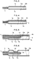
- FIG. 3 is an enlarged schematic cross sectional view of the embodiment of FIG. 1 taken along line B-B.
- FIG. 4 is an enlarged schematic cross sectional view of the embodiment of FIG. 1 taken along line C-C.
- FIG. 5 is an enlarged schematic cross sectional view of the embodiment of FIG. 1 taken along line D-D.
- FIG. 6 is an enlarged schematic cross sectional view of the embodiment of FIG. 1 taken along line E-E.
- FIG. 7 is an enlarged schematic cross sectional view of the embodiment of FIG. 1 taken along line F-F.
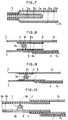
- FIG. 8 is an enlarged schematic cross sectional view of the embodiment of FIG. 1 taken along line G-G.
- FIG. 9 is an enlarged schematic cross sectional view of an embodiment obtained by modifying the embodiment of FIG. 8.
- FIG. 10 is an enlarged schematic cross sectional view of another embodiment obtained by modifying the embodiment of FIG. 8.
- FIG. 11 is a partly cut-away schematic front view of another embodiment of bag according to the invention.
- FIG. 12 is an enlarged schematic cross sectional view of the embodiment of FIG. 11 taken along line A-A.
- FIG. 13 is an enlarged schematic cross sectional view of the embodiment of FIG. 11 taken along line B-B.
- FIG. 14 is an enlarged schematic cross sectional view of the embodiment of FIG. 11 taken along line C-C.
- FIG. 15 is an enlarged schematic cross sectional view of the embodiment of FIG. 11 taken along line D-D.
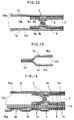
- FIG. 16 is an enlarged schematic cross sectional view of the embodiment of FIG. 11 taken along line E-E.
- FIG. 17 is an enlarged schematic cross sectional view of the embodiment of FIG. 11 taken along line F-F.
- FIG. 18 is an enlarged schematic cross sectional view of the embodiment of FIG. 11 taken along line G-G.
- FIG. 19 is an enlarged schematic cross sectional view of the embodiment of FIG. 11 taken along line H-H.
- FIG. 20 is a schematic front view of still another embodiment of the invention.
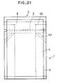
- FIG. 21 is a schematic front view of still another embodiment of the invention.
- FIG. 22 is a schematic front view of still another embodiment of the invention.
- FIG. G. 23 is a schematic side view of a method of manufacturing a bag according to the invention, showing its principal areas.
- FIG. 24 is a schematic plan view of the illustration of FIG. 23.
- a first embodiment of bag according to the invention comprises a front film member 1a and a rear film member 1b, each of which carries a thermoadhesive resin layer arranged on the inside thereof.
- the bag also has an opening 2, a fastener 3 arranged along the opening 2 and a pair of notches 7 arranged above the opposite ends of the opening 2 (or a notch 7 arranged above one of the opposite ends of the opening 2) in alignment with a cutting line 6 running above and in parallel with the fastener 3 to facilitate the operation of cutting the bag.
- the cutting line 6 and the notches (or notch) 7 are provided only when necessary.
- Reference numeral 4 denotes a pair of side gussets whose inner surface is thermally adhesive relative to that of the film members 1a and 1b and each of which is folded between the film members 1a and 1b with the outer surface facing inside to show a V-shaped cross section.
- the upper edges 4b of the side gussets 4, 4 are thermally adhesive relative to the inner surface of the film members 1a and 1b and that of the side gussets 4, 4 and bonded to the inner surface of either one of the film members 1a and 1b by means of a sealing tape 8 provided either with a female profile 3a or with a male profile 3b of a snap-fit type fastener 3.
- the upper edges of the side gussets are bonded to the inner surface of the front film member 1a by means of a sealing tape 8 provided with a female profile 3a of a snap-fit type fastener.
- each of the side gussets 4, 4 may additionally be bonded to the front film member 1a along an oblique line 4d running from the upper edge 4b or a point close to and below the fastener 3 to a point on the corresponding lateral edge 5 of the front film member 1a.
- the front and rear film members 1a and 1b, the side gussets 4, 4 and the paired sealing tapes 8, 8 provided respectively with a female profile and a male profile of snap-fit type fastener are made of multilayer film having a configuration as described hereinafter.
- the front and rear film members 1a and 1b comprise an outer film layer 10a and an inner film layer 10b.
- the side gussets 4, 4 comprise an outer film layer 11a and an inner film layer 11b.
- the inner film layers 10b of the film members and the inner film layers 11b of the side gussets are typically made of a resin material that makes the inner film layers 10b and 10b and the inner film layers 10b, 10b and 11b, 11b thermally highly adhesive relative to each other such as low density polyethylene (hereinafter referred to as LDPE), polypropylene or ethylene acetate vinyl copolymer (hereinafter referred to as EVA), whereas the outer film layers 10a of the film members and the outer film layers 11a of the side gussets are typically made of a monolayer or multilayer material that does not become thermally adhesive under the condition where the inner film layers 10b, 10b and 11b, 11b are thermally bonded and is capable of endowing the bag with certain desired properties including thermal resistance, air tightness, a light screening effect, a flavour retaining effect and mechanical strength.
- a material may be selected from polyester film (hereinafter referred to as PET), polyamide, paper and aluminum foil.
- each of the paired sealing tapes 8, 8 has a multilayer structure having a thermoadhesive high-melting point layer 8a typically made of straight-chain low density polyethylene (hereinafter referred to as LLDPE) on the side where the tapes are to be held in contact with each other and another layer 8b typically made of EVA or LDPE having a melting point lower than that of the layer 8a and a good adhesiveness relative to the inner film layers 11b, 11b of the side gussets 4, 4 and the inner film layer 10b of the front film member 1a.
- LLDPE straight-chain low density polyethylene
- any two of them can be thermally bonded together excellently at intended surfaces areas under intended conditions, whereas they are effectively prevented from adhering to each other at any unintended surface areas under the conditions they are subjected to.
- the related edges 5, 5 of the front and rear film members together at areas where the layers 8a, 8a of the sealing tapes 8, 8 put to contact with each other they will only have to be heated to the melting point of LLDPE.
- the inner film layer 10b of the front film member 1a, the inner film layers 11b, 11b of the side gussets 4, 4 and the layer 8b of the corresponding one of the paired sealing tapes 8, 8 are excellently bonded together due to the coordination in terms of thermoadhesiveness and the face that each of the sealing tapes 8 has layers 8a and 8b made of respective thermoadhesive resin materials having different melting points.
- the inner film layer 10b of the rear film member 1b and the layer 8b of the corresponding one of the paired sealing tapes 8, 8 are excellently bonded together due to the coordination in terms of thermoadhesiveness, whereas the layers 8a and 8a of the paired sealing tapes 8, 8 are prevented from being bonded to each other under the above bonding conditions.
- the paired sealing tapes 8, 8 provided with respective members of a fastener 3 can be fitted properly onto the inner surface of the bag 1 at the opening 2 so that the fastener 3 will not come off from the inner surface if the bag is subjected to impact or opened and closed repeatedly.
- L2 in FIGS. 1 and 11 denotes the total length of the opening 2.
- the inner film layer 11b of each of the side gussets 4, 4 is thermally bonded to the inner film layer 10b of the front film member 1a along the oblique bonding line 4d so that, when the bag 1 is filled with the contents to extend the side gussets 4, 4 as shown in FIG. 2, the oblique bonding lines 4d, 4d alleviate the concentration of stress onto the upper edges 4b, 4b of the side gussets 4, 4 bonded by one of the sealing tapes 8, 8.
- the inner layers of the side gussets 4, 4 are thermally adhesive relative to the inner layers of the front and rear film members 1a and 1b and the upper edges 4b, 4b of the side gussets 4, 4 are bonded to either the front film member 1a or the rear film member 1b by the corresponding one of the sealing tapes 8, 8 provided respectively with the female profile 3a and the male profile 3b of the snap-fit type fastener 3, the positional relationship between the upper edges 4b, 4b of the side gussets 4, 4 and the fastener 3 on the sealing tapes 8, 8 can be modified by selecting appropriate dimensions for the side gussets 4, 4.
- the side gussets 4, 4 may be so dimensioned that the upper edges 4b, 4b of the side gussets 4, 4 are located below the fastener 3 arranged on the sealing tapes 8, 8.
- the side gussets 4, 4 are extended at positions remote from the fastener 3 with the upper edges 4b, 4b located between them when the bag is filled with the contents.
- FIGS. 9 and 10 illustrate embodiments different from the one shown in FIGS. 1 through 8.
- the sealing tapes 8, 8 provided respectively with the female profile 3a and the male profile 3b of the snap-fit type fastener 3 have different heights.
- the sealing tapes 8, 8 are bonded to the bag 1 differently. Note that, however, the layered arrangement of the front and rear film members 1a, 1b, the side gussets 4, 4 and the sealing tapes 8, 8 provided with the respective members of the fastener are not limited to the above embodiments and may be modified appropriately to optimize the usability of the bag.
- the side gussets 4, 4 may be so dimensioned that the upper edges 4b, 4b of the side gussets 4, 4 are located above the fastener 3 arranged on the sealing tapes 8, 8 and hence closer to the opening 2 of the bag 1 and then bonded to the inner surface of either the front film member 1a or the rear film member 1b.
- FIGS. 11 through 20 shows an embodiment where the upper edges 4b, 4b of the side gussets 4, 4 are aligned with the upper edges of the film members 1a and 1b defining the opening 2 of the bag
- FIGS. 21 and 22 illustrate several different embodiments where the upper edges 4b, 4b of the side gussets 4, 4 are also located above the fastener 3 arranged on the sealing tapes 8, 8.
- the side gussets 4, 4 When the-upper edges 4b, 4b of the side gussets 4, 4 are located above the fastener 3 arranged on the sealing tapes 8, 8, the side gussets 4, 4 can be made to become extended at positions close to the fastener 3 in a well balanced manner to improve the appearance of the bag.
- the extended state of the side gussets reflect the fact that the extended state of the side gussets and hence that of the bag as a hole are defined by the positional relationship between the upper edges of the side gussets 4, 4 that are bonded to the inner surface of one of the film members 1a and 1b by means of corresponding one of the sealing tapes 8, 8 and the fastener 1 arranged on the sealing tapes. They are put under stress separately if they are remote from each other, whereas they are collectively and commonly put under stress if they are located closer relative to each other.
- the upper edges 4b, 4b of the side gussets 4, 4 are preferably arranged close to the fastener 3 so that the side gussets 4, 4 may be extended at locations close to the fastener 3.
- the sealing tapes 8, 8 are preferably bonded in areas located above and close to the fastener 3 to minimize or totally eliminate the bonded areas of the sealing tapes 8, 8 under the fastener 3, (although, the bonded areas under the fastener 3 are not totally eliminated in any of the illustrated embodiments).
- FIG. 20 shows an embodiment designed to be filled through the bottom 20 of the bag 1.
- reference symbols 5a and 5b denote respectively the bottom area and the top area to be sealed after filling the bag.
- the upper edges of the sealing tapes 8, 8 provided with a fastener are aligned with the opening 2 and the upper edges 4b, 4b of the side gussets 4, 4 in the embodiments shown in FIGS. 11 through 20.
- the bag is made free from the risk of producing a pin hole or some other flaw due to the thick side gussets 4, 4 when the bag 1 is sealed at the opening 2.
- the bag is held airtight and shows an agreeable appearance.
- FIG. 21 shows an embodiment where the upper edges 4b, 4b of the side gussets 4, 4 are located above the fastener 3 on the sealing tapes 8, 8 and below the opening 2 of the bag 1.
- the sealing tapes 8, 8 does not-cover the upper edges of the side gussets 4, 4, although they come to cover the effective upper edges 4b, 4b of the side gussets 4, 4 that appear when the seal of the bag is opened by way of the notches 7, 7. Therefore, the net effect of this embodiment will be practically same as that of the preceding embodiments.
- the film members of the bag and the snap-fit type fastener are formed integrally and the upper edges of the side gussets are securely fitted to the inside of the bag by means of an independent sealing tap. Therefore, the snap-fit type fastener and the sealing tape have to be manufactured independently, placed in position on the film members of the bag and then bonded firmly to the bag. Thus, the process of manufacturing the bag is rather cumbersome and costly.
- the sealing tapes 8, 8 for firmly holding the upper edges 4b, 4b of the side gussets 4, 4 to the inside of the bag are provided respectively with a female profile and a male profile of a snap-fit type fastener and therefore manufactured integrally so that the number of the components of the bag is reduced and the process of manufacturing the bag is considerably simplified to improve the productivity and reduce the manufacturing cost.
- a roll of film having a thermoadhesive resin layer is unrolled to produce a pair of film members of the bag in such a way that the paired film members are separated from each other with the thermoadhesive resin layers facing each other.
- FIGS. 23 and 24 illustrating a technique that can be used for the purpose of the invention, the roll of film 20 having a thermoadhesive resin layer is unrolled and folded with the thermoadhesive resin layer located inside and cut along the fold line by means of a cutting edge 22 to produce a pair of film members 1a and 1b.
- a pair of film members 1a and 1b may be produced by using a pair of rolls of film.
- the rolls may have a width adapted to the film members of the bag to be produced or, alternatively, they may have a greater width so that a plurality of bags may be produced simultaneously for the purpose of mass production.
- the vertically separated film members 1a and 1b are then moved away from each other by means of feed rollers. Meanwhile, a roll of sealing tapes 8, 8 provided respectively with and put together through the engagement of female 3a and male profiles 3b of fastener is unrolled and the sealing tapes 8, 8 are separated from each other by disengaging the female and male profiles 3a and 3b. The sealing tapes are then made to run between and along the upper and lower film members 1a and 1b respectively.
- a pair of side gussets 4 folded to show a V-shaped cross section by means of a folder 23 and cut to given dimensions by a cutter 24 are inserted between the film members 1a and 1b and also between the sealing tapes 8, 8 in a direction perpendicular to the running direction of the film members 1a and 1b and then the upper edges 4b, 4b of the side gussets 4, 4 are temporarily bonded to the corresponding film member after adjusting their positions relative to the fastener 3 on the sealing tapes 8, 8.
- the female profile 3a and the male profile 3b of the fastener are made to engage with each other by engaging means 27 and the top, the bottom and the lateral sides of the film members 1a and 1b are bonded and cut to given dimensions to produce a final product of bag by using of known techniques.
- the side gussets are bonded to the inner surface of either one of the front and rear film members by means of one of a pair of sealing tapes provided respectively with a female profile and a male profile of the snap-fit type fastener and having thermoadhesiveness relative to the inner layers of said film members and the those of the side gussets so that, when the bag is opened by disengaging the female profile and the male profile of the fastener, the bag is fully opened along the proper opening of the bag and the contents can be taken out through the opening smoothly without any interference on the part of the upper edges of the side gussets.
- sealing tapes are realized as a single component and provided with a snap-fit type fastener as an integral part thereof, the number of components of the bag is reduced and the manufacturing process is simplified to improve the productivity and reduce the manufacturing cost.
- the sealing tapes with a fastener have a multilayer structure of resin layers with different melting points, the sealing tapes are prevented from adhering to each other when they are bonded to the film members and the side gussets so that consequently, the fastener is prevented from disengagement and damage and the manufacturing process of the bag can be further simplified to improve the productivity and reduce the manufacturing cost.
- the side gussets are so dimensioned that the upper edges of said side gussets are bonded to the corresponding film member at positions located above the fastener on the sealing tapes, the side gussets can be made to become extended at positions close to the fastener in a well balanced manner to improve the appearance of the bag at the retail outlet. Additionally, the capacity of the bag is significantly improved because the side gussets can be extended immediately under the fastener.
- the bag is made free from the risk of producing a pin hole or some other flaw due to the thick side gussets when the bag 1 is sealed at the opening.
- the bag is held airtight and shows an agreeable appearance.
Priority Applications (2)
| Application Number | Priority Date | Filing Date | Title |
|---|---|---|---|
| EP19970303769 EP0834454B1 (de) | 1997-06-03 | 1997-06-03 | Beutel mit Verschluss aus Kunststoff und Verfahren zu dessen Herstellung |
| DE1997601273 DE69701273T2 (de) | 1997-06-03 | 1997-06-03 | Beutel mit Verschluss aus Kunststoff und Verfahren zu dessen Herstellung |
Applications Claiming Priority (1)
| Application Number | Priority Date | Filing Date | Title |
|---|---|---|---|
| EP19970303769 EP0834454B1 (de) | 1997-06-03 | 1997-06-03 | Beutel mit Verschluss aus Kunststoff und Verfahren zu dessen Herstellung |
Publications (2)
| Publication Number | Publication Date |
|---|---|
| EP0834454A1 true EP0834454A1 (de) | 1998-04-08 |
| EP0834454B1 EP0834454B1 (de) | 2000-02-09 |
Family
ID=8229353
Family Applications (1)
| Application Number | Title | Priority Date | Filing Date |
|---|---|---|---|
| EP19970303769 Expired - Lifetime EP0834454B1 (de) | 1997-06-03 | 1997-06-03 | Beutel mit Verschluss aus Kunststoff und Verfahren zu dessen Herstellung |
Country Status (2)
| Country | Link |
|---|---|
| EP (1) | EP0834454B1 (de) |
| DE (1) | DE69701273T2 (de) |
Cited By (19)
| Publication number | Priority date | Publication date | Assignee | Title |
|---|---|---|---|---|
| EP0792634A2 (de) | 1996-02-29 | 1997-09-03 | Unilever Plc | Präparat für Aerosol-Antitranspirant und Verfahren zur Herstellung |
| EP0812776A2 (de) * | 1996-06-14 | 1997-12-17 | Kabushiki Kaisha Meiwa Pax | Seitenfaltbeutel mit Reissverschluss sowie Verfahren zu seiner Herstellung |
| EP0995695A1 (de) * | 1998-10-23 | 2000-04-26 | P.F.M. S.p.A. | Beutel für Nahrungsmittel aus abziehbaren Folien und Verfahren zur Hestellung |
| WO2002036449A2 (de) | 2000-11-02 | 2002-05-10 | Klaus Reinhold Maschinen- und Gerätebau GmbH | Verpackungsbeutel aus kunststoffolie mit seitenfalten |
| FR2816597A1 (fr) * | 2000-11-15 | 2002-05-17 | Autobar Flexible France | Sac d'emballage |
| WO2001089946A3 (en) * | 2000-05-24 | 2002-05-23 | Colgate Palmolive Co | Reclosable bag |
| EP1360912A2 (de) * | 2002-05-10 | 2003-11-12 | Bischof und Klein GmbH & Co. | Wiederverschliessbares Verpackungsbehältnis |
| WO2005063588A1 (en) * | 2003-12-19 | 2005-07-14 | Sonoco Development, Inc. | Side gusset bag with reclose feature |
| EP1754596A1 (de) * | 2005-08-19 | 2007-02-21 | Nordenia Deutschland Halle GmbH | Verfahren zur Herstellung von Folienbeuteln mit Seitenfalten |
| EP1795335A2 (de) | 2005-12-08 | 2007-06-13 | B&B - MAF GmbH & Co. KG | Verfahren zur Herstellung eines Packmittels aus flexiblem Material |
| WO2008048640A2 (en) | 2006-10-17 | 2008-04-24 | The Hudson-Sharp Machine Co. | Method of making bag with interrupted side gussets |
| EP2032454A1 (de) | 2006-06-22 | 2009-03-11 | Nordenia Deutschland Halle GmbH | Folienbeutel |
| US7597657B2 (en) | 2003-04-15 | 2009-10-06 | Yeager James W | Package having reclosable pour spout and method of forming same |
| EP2114783A1 (de) | 2007-01-12 | 2009-11-11 | Alcan Packaging Arenzano S.p.a. | Flexibler behälter mit anklebendem griff |
| EP2284091A1 (de) * | 2009-08-14 | 2011-02-16 | Nordenia Deutschland Halle GmbH | Seitenfaltenbeutel aus einer Kunststofffolie |
| DE102005026149B4 (de) * | 2005-06-06 | 2011-05-26 | Nordenia Deutschland Halle Gmbh | Verfahren zur Herstellung von Folienbeuteln |
| US8104961B2 (en) | 2009-03-24 | 2012-01-31 | Coating Excellence International Llc | Bag and zipper assembly with secured side gussets |
| US8182407B2 (en) | 2005-10-18 | 2012-05-22 | Innoflex Incorporated | Package having recloseable pour spout |
| US20210394965A1 (en) * | 2018-09-25 | 2021-12-23 | Tecksom International Limited | A bag and related methods |
Families Citing this family (4)
| Publication number | Priority date | Publication date | Assignee | Title |
|---|---|---|---|---|
| DE20017182U1 (de) * | 2000-10-06 | 2002-02-14 | Bischof Und Klein Gmbh & Co Kg | Seitenfaltenbeutel aus flexiblen schweißbarem Material |
| US7144159B2 (en) * | 2003-01-29 | 2006-12-05 | Illinois Tool Works Inc. | Gusseted reclosable package with slider-operated zipper |
| DE202004006856U1 (de) * | 2004-04-29 | 2005-09-08 | Bischof + Klein Gmbh & Co. Kg | Wiederverschließbares Verpackungsbehältnis |
| JP2023149921A (ja) * | 2022-03-31 | 2023-10-16 | タキロンシーアイ株式会社 | 嵌合具及び嵌合具付き袋体 |
Citations (7)
| Publication number | Priority date | Publication date | Assignee | Title |
|---|---|---|---|---|
| US4620320A (en) * | 1984-12-20 | 1986-10-28 | Kcl Corporation | Substantially leakproof zipper closure for bags and method |
| US4736450A (en) * | 1985-11-20 | 1988-04-05 | Minigrip, Inc. | Gusseted bags with reclosure features |
| US5094707A (en) * | 1990-07-25 | 1992-03-10 | Bruno Edward C | Apparatus for extruding plastic storage bags |
| JPH0597151A (ja) * | 1991-10-04 | 1993-04-20 | Seisan Nipponsha Kk | 合成樹脂製チヤツク付の袋体 |
| US5364189A (en) * | 1993-07-09 | 1994-11-15 | Kabushiki Kaisha Hosokawa Yoko | Zippered bag and method of forming the same |
| JPH0834450A (ja) * | 1994-07-25 | 1996-02-06 | Seisan Nipponsha Kk | 合成樹脂製チャック付の袋体 |
| EP0760340A1 (de) * | 1995-09-04 | 1997-03-05 | Idemitsu Petrochemical Co., Ltd. | Druckknopf und diesen aufweisender Verpackungssack |
-
1997
- 1997-06-03 DE DE1997601273 patent/DE69701273T2/de not_active Expired - Lifetime
- 1997-06-03 EP EP19970303769 patent/EP0834454B1/de not_active Expired - Lifetime
Patent Citations (7)
| Publication number | Priority date | Publication date | Assignee | Title |
|---|---|---|---|---|
| US4620320A (en) * | 1984-12-20 | 1986-10-28 | Kcl Corporation | Substantially leakproof zipper closure for bags and method |
| US4736450A (en) * | 1985-11-20 | 1988-04-05 | Minigrip, Inc. | Gusseted bags with reclosure features |
| US5094707A (en) * | 1990-07-25 | 1992-03-10 | Bruno Edward C | Apparatus for extruding plastic storage bags |
| JPH0597151A (ja) * | 1991-10-04 | 1993-04-20 | Seisan Nipponsha Kk | 合成樹脂製チヤツク付の袋体 |
| US5364189A (en) * | 1993-07-09 | 1994-11-15 | Kabushiki Kaisha Hosokawa Yoko | Zippered bag and method of forming the same |
| JPH0834450A (ja) * | 1994-07-25 | 1996-02-06 | Seisan Nipponsha Kk | 合成樹脂製チャック付の袋体 |
| EP0760340A1 (de) * | 1995-09-04 | 1997-03-05 | Idemitsu Petrochemical Co., Ltd. | Druckknopf und diesen aufweisender Verpackungssack |
Non-Patent Citations (2)
| Title |
|---|
| PATENT ABSTRACTS OF JAPAN vol. 017, no. 439 (M - 1462) 13 August 1993 (1993-08-13) * |
| PATENT ABSTRACTS OF JAPAN vol. 096, no. 006 28 June 1996 (1996-06-28) * |
Cited By (30)
| Publication number | Priority date | Publication date | Assignee | Title |
|---|---|---|---|---|
| EP0792634A2 (de) | 1996-02-29 | 1997-09-03 | Unilever Plc | Präparat für Aerosol-Antitranspirant und Verfahren zur Herstellung |
| EP0812776A2 (de) * | 1996-06-14 | 1997-12-17 | Kabushiki Kaisha Meiwa Pax | Seitenfaltbeutel mit Reissverschluss sowie Verfahren zu seiner Herstellung |
| EP0812776A3 (de) * | 1996-06-14 | 1998-12-09 | Kabushiki Kaisha Meiwa Pax | Seitenfaltbeutel mit Reissverschluss sowie Verfahren zu seiner Herstellung |
| EP0995695A1 (de) * | 1998-10-23 | 2000-04-26 | P.F.M. S.p.A. | Beutel für Nahrungsmittel aus abziehbaren Folien und Verfahren zur Hestellung |
| WO2001089946A3 (en) * | 2000-05-24 | 2002-05-23 | Colgate Palmolive Co | Reclosable bag |
| US6461043B1 (en) | 2000-05-24 | 2002-10-08 | Colgate Palmolive Company | Reclosable bag |
| WO2002036449A2 (de) | 2000-11-02 | 2002-05-10 | Klaus Reinhold Maschinen- und Gerätebau GmbH | Verpackungsbeutel aus kunststoffolie mit seitenfalten |
| WO2002036449A3 (de) * | 2000-11-02 | 2002-09-19 | Reinhold Klaus Masch & Geraete | Verpackungsbeutel aus kunststoffolie mit seitenfalten |
| FR2816597A1 (fr) * | 2000-11-15 | 2002-05-17 | Autobar Flexible France | Sac d'emballage |
| EP1360912A2 (de) * | 2002-05-10 | 2003-11-12 | Bischof und Klein GmbH & Co. | Wiederverschliessbares Verpackungsbehältnis |
| EP1360912A3 (de) * | 2002-05-10 | 2004-05-19 | Bischof und Klein GmbH & Co. | Wiederverschliessbares Verpackungsbehältnis |
| AU2003204042B2 (en) * | 2002-05-10 | 2009-06-04 | Bischof + Klein Se & Co. Kg | Reclosable packaging container |
| US7192191B2 (en) | 2002-05-10 | 2007-03-20 | Bishof + Klein Gmbh & Co. Kg | Reclosable packaging container |
| US7597657B2 (en) | 2003-04-15 | 2009-10-06 | Yeager James W | Package having reclosable pour spout and method of forming same |
| US7223017B2 (en) | 2003-12-19 | 2007-05-29 | Sonoco Development, Inc. | Side gusset bag with reclose feature |
| WO2005063588A1 (en) * | 2003-12-19 | 2005-07-14 | Sonoco Development, Inc. | Side gusset bag with reclose feature |
| DE102005026149B4 (de) * | 2005-06-06 | 2011-05-26 | Nordenia Deutschland Halle Gmbh | Verfahren zur Herstellung von Folienbeuteln |
| EP1754596A1 (de) * | 2005-08-19 | 2007-02-21 | Nordenia Deutschland Halle GmbH | Verfahren zur Herstellung von Folienbeuteln mit Seitenfalten |
| US9315299B2 (en) | 2005-10-18 | 2016-04-19 | Innoflex Incorporated | Package having recloseable pour spout |
| US8182407B2 (en) | 2005-10-18 | 2012-05-22 | Innoflex Incorporated | Package having recloseable pour spout |
| EP1795335A3 (de) * | 2005-12-08 | 2008-06-11 | B&B - MAF GmbH & Co. KG | Verfahren zur Herstellung eines Packmittels aus flexiblem Material |
| EP1795335A2 (de) | 2005-12-08 | 2007-06-13 | B&B - MAF GmbH & Co. KG | Verfahren zur Herstellung eines Packmittels aus flexiblem Material |
| EP2032454A1 (de) | 2006-06-22 | 2009-03-11 | Nordenia Deutschland Halle GmbH | Folienbeutel |
| US8137254B2 (en) | 2006-10-17 | 2012-03-20 | Hudson-Sharp Machine Co. | Method of making bag with interrupted side gussets |
| WO2008048640A2 (en) | 2006-10-17 | 2008-04-24 | The Hudson-Sharp Machine Co. | Method of making bag with interrupted side gussets |
| EP2114783A1 (de) | 2007-01-12 | 2009-11-11 | Alcan Packaging Arenzano S.p.a. | Flexibler behälter mit anklebendem griff |
| US8104961B2 (en) | 2009-03-24 | 2012-01-31 | Coating Excellence International Llc | Bag and zipper assembly with secured side gussets |
| EP2284091A1 (de) * | 2009-08-14 | 2011-02-16 | Nordenia Deutschland Halle GmbH | Seitenfaltenbeutel aus einer Kunststofffolie |
| US20210394965A1 (en) * | 2018-09-25 | 2021-12-23 | Tecksom International Limited | A bag and related methods |
| US11827418B2 (en) * | 2018-09-25 | 2023-11-28 | Tecksom International Limited | Bag and related methods |
Also Published As
| Publication number | Publication date |
|---|---|
| DE69701273D1 (de) | 2000-03-16 |
| DE69701273T2 (de) | 2000-09-28 |
| EP0834454B1 (de) | 2000-02-09 |
Similar Documents
| Publication | Publication Date | Title |
|---|---|---|
| EP0834454B1 (de) | Beutel mit Verschluss aus Kunststoff und Verfahren zu dessen Herstellung | |
| EP0982117B1 (de) | Zwischenlage für einen Befestigungsstreifen | |
| US5238306A (en) | Method of producing a sealing system for a reclosable webbed-wall package, and system made | |
| US5875611A (en) | Offset sealing method for plastic films | |
| EP0887276B1 (de) | Profilverschluss versehen mit einer abziehbaren Schicht | |
| US5022530A (en) | Modified zipper elements for easy open containers | |
| CA2776965C (en) | Carton with plastic reclosable header | |
| US6830377B2 (en) | Reclosable packaging with gas barrier incorporated in zipper | |
| US6988828B2 (en) | Closure for containers and reclosable containers including the same | |
| EP1621473A1 (de) | Originalitätsgesicherter Beutel mit einem Reissverschluss mit Schieber und Verfahren zu deren Herstellung | |
| US20040161167A1 (en) | Tamper-evident reclosable bag having slider-actuated string zipper | |
| US20070292053A1 (en) | Polywoven pinch bottom open mouth bag | |
| JPH1059387A (ja) | サイドガゼット袋およびその製造法 | |
| CA2032242A1 (en) | Method of making dual reclosable pouches | |
| US7465265B2 (en) | Method for installing closure in mouth of pre-made bag | |
| US5774954A (en) | Peel seal zipper tape | |
| MXPA02001999A (es) | Metodo para fabricar empaques resellables. | |
| US20070180667A1 (en) | Teardrop sealant layer for profile and spacer areas for improved sealing and guiding | |
| CA2083763A1 (en) | Tamper-evident zipper closed package | |
| EP1447339B1 (de) | Originalitätsgesicherter Beutel mit einem Reissverschluss mit Schieber | |
| US20200165047A1 (en) | Bottom gusset package with folded gusset | |
| EP0881156B1 (de) | Komplementärer Profilverschlussstreifen mit einer abreissbaren Abdichtungsschicht | |
| CA2007125A1 (en) | Packing, a method of manufacturing the packing, and a strip material therefor |
Legal Events
| Date | Code | Title | Description |
|---|---|---|---|
| PUAI | Public reference made under article 153(3) epc to a published international application that has entered the european phase |
Free format text: ORIGINAL CODE: 0009012 |
|
| AK | Designated contracting states |
Kind code of ref document: A1 Designated state(s): DE FR GB |
|
| 17P | Request for examination filed |
Effective date: 19980424 |
|
| AKX | Designation fees paid |
Free format text: DE FR GB |
|
| RBV | Designated contracting states (corrected) |
Designated state(s): DE FR GB |
|
| 17Q | First examination report despatched |
Effective date: 19981112 |
|
| GRAG | Despatch of communication of intention to grant |
Free format text: ORIGINAL CODE: EPIDOS AGRA |
|
| GRAG | Despatch of communication of intention to grant |
Free format text: ORIGINAL CODE: EPIDOS AGRA |
|
| GRAH | Despatch of communication of intention to grant a patent |
Free format text: ORIGINAL CODE: EPIDOS IGRA |
|
| GRAH | Despatch of communication of intention to grant a patent |
Free format text: ORIGINAL CODE: EPIDOS IGRA |
|
| GRAA | (expected) grant |
Free format text: ORIGINAL CODE: 0009210 |
|
| AK | Designated contracting states |
Kind code of ref document: B1 Designated state(s): DE FR GB |
|
| REF | Corresponds to: |
Ref document number: 69701273 Country of ref document: DE Date of ref document: 20000316 |
|
| ET | Fr: translation filed | ||
| PLBE | No opposition filed within time limit |
Free format text: ORIGINAL CODE: 0009261 |
|
| STAA | Information on the status of an ep patent application or granted ep patent |
Free format text: STATUS: NO OPPOSITION FILED WITHIN TIME LIMIT |
|
| 26N | No opposition filed | ||
| REG | Reference to a national code |
Ref country code: FR Ref legal event code: TP |
|
| REG | Reference to a national code |
Ref country code: GB Ref legal event code: IF02 |
|
| REG | Reference to a national code |
Ref country code: GB Ref legal event code: 732E |
|
| REG | Reference to a national code |
Ref country code: FR Ref legal event code: PLFP Year of fee payment: 19 |
|
| PGFP | Annual fee paid to national office [announced via postgrant information from national office to epo] |
Ref country code: FR Payment date: 20150624 Year of fee payment: 19 |
|
| PGFP | Annual fee paid to national office [announced via postgrant information from national office to epo] |
Ref country code: DE Payment date: 20150713 Year of fee payment: 19 Ref country code: GB Payment date: 20150717 Year of fee payment: 19 |
|
| REG | Reference to a national code |
Ref country code: DE Ref legal event code: R119 Ref document number: 69701273 Country of ref document: DE |
|
| GBPC | Gb: european patent ceased through non-payment of renewal fee |
Effective date: 20160603 |
|
| REG | Reference to a national code |
Ref country code: FR Ref legal event code: ST Effective date: 20170228 |
|
| PG25 | Lapsed in a contracting state [announced via postgrant information from national office to epo] |
Ref country code: DE Free format text: LAPSE BECAUSE OF NON-PAYMENT OF DUE FEES Effective date: 20170103 Ref country code: FR Free format text: LAPSE BECAUSE OF NON-PAYMENT OF DUE FEES Effective date: 20160630 |
|
| PG25 | Lapsed in a contracting state [announced via postgrant information from national office to epo] |
Ref country code: GB Free format text: LAPSE BECAUSE OF NON-PAYMENT OF DUE FEES Effective date: 20160603 |