EP0834298B1 - Anbauteil zur lösbaren Befestigung an Sitzeinrichtungen - Google Patents
Anbauteil zur lösbaren Befestigung an Sitzeinrichtungen Download PDFInfo
- Publication number
- EP0834298B1 EP0834298B1 EP96115926A EP96115926A EP0834298B1 EP 0834298 B1 EP0834298 B1 EP 0834298B1 EP 96115926 A EP96115926 A EP 96115926A EP 96115926 A EP96115926 A EP 96115926A EP 0834298 B1 EP0834298 B1 EP 0834298B1
- Authority
- EP
- European Patent Office
- Prior art keywords
- frame
- locking
- mounting device
- locking mechanism
- shaft
- Prior art date
- Legal status (The legal status is an assumption and is not a legal conclusion. Google has not performed a legal analysis and makes no representation as to the accuracy of the status listed.)
- Expired - Lifetime
Links
Images


Classifications
-
- A—HUMAN NECESSITIES
- A47—FURNITURE; DOMESTIC ARTICLES OR APPLIANCES; COFFEE MILLS; SPICE MILLS; SUCTION CLEANERS IN GENERAL
- A47C—CHAIRS; SOFAS; BEDS
- A47C7/00—Parts, details, or accessories of chairs or stools
- A47C7/54—Supports for the arms
- A47C7/546—Supports for the arms of detachable type
-
- A—HUMAN NECESSITIES
- A61—MEDICAL OR VETERINARY SCIENCE; HYGIENE
- A61G—TRANSPORT, PERSONAL CONVEYANCES OR ACCOMMODATION SPECIALLY ADAPTED FOR PATIENTS OR DISABLED PERSONS; OPERATING TABLES OR CHAIRS; CHAIRS FOR DENTISTRY; FUNERAL DEVICES
- A61G5/00—Chairs or personal conveyances specially adapted for patients or disabled persons, e.g. wheelchairs
- A61G5/10—Parts, details or accessories
- A61G5/12—Rests specially adapted therefor, e.g. for the head or the feet
-
- A—HUMAN NECESSITIES
- A61—MEDICAL OR VETERINARY SCIENCE; HYGIENE
- A61G—TRANSPORT, PERSONAL CONVEYANCES OR ACCOMMODATION SPECIALLY ADAPTED FOR PATIENTS OR DISABLED PERSONS; OPERATING TABLES OR CHAIRS; CHAIRS FOR DENTISTRY; FUNERAL DEVICES
- A61G5/00—Chairs or personal conveyances specially adapted for patients or disabled persons, e.g. wheelchairs
- A61G5/10—Parts, details or accessories
- A61G5/12—Rests specially adapted therefor, e.g. for the head or the feet
- A61G5/125—Rests specially adapted therefor, e.g. for the head or the feet for arms
Definitions
- the present invention relates to an attachment according to the Preamble of claim 1, for example a Armrest for detachable attachment to seat equipment, especially on electric or hand-operated wheelchairs.
- Wheelchairs and other seating arrangements for in your People with reduced mobility are often modular built and can adapt to different User needs can be modified by characteristic technical elements such as armrests, Leg supports, holding devices, drive devices etc. are interchangeable or expandable as attachments. Thereby can the room for maneuver, security, function and appearance improved by wheelchairs or other seating arrangements become. Furthermore, these facilities for the Transport in vehicles can be dismantled, so that attachments as simple as possible, preferably dismantled by the user himself can be.
- An armrest designed as an attachment with the features of the preamble of claim 1 is from US-A-5 544 940 known. This armrest must be dismantled by one A front lock can be manually released and wheelchair a rear locking is when the Armrest frame automatically unlocked around a swivel axis. The rear intake is by a on the frame of the wheelchair attached and even after removing the armrest there remaining unit formed, one on a pivot axis stored sleeve and one accommodated in the sleeve Unlocking mechanism includes.
- the Unlocking mechanism includes one on a leaf spring attached button that protrudes from the pivoting sleeve.
- the button is in the non-pivoted position of the sleeve on the frame of the wheelchair and is against the effect of Leaf spring pressed into the sleeve.
- too second button attached to the leaf spring into a hole in the Frame of the armrest pressed and prevents the removal of the Armrest from the sleeve.
- This armrest already offers simplified unlocking, handling when removing is still complicated and that Unlocking mechanism not independent of the wheelchair.
- an attachment in particular an armrest for releasable attachment to a To create seating, in particular a wheelchair, that regarding the unlocking mechanism and the Handling when mounting and dismounting is improved.
- the attachment according to the invention has the advantage that when the attachment is removed, only the first fastening device is first released by hand and then the entire attachment is pivoted in a specific, defined direction.
- the second fastening device When swiveling, the second fastening device is automatically released and the attachment can be removed. A user therefore only has to release one lock directly while the second lock is released automatically with the pivoting movement. This allows the attachment to be unlocked and removed using one-hand operation. At the same time, only a small force is required to release the second lock, since the entire add-on part acts as a lever during the pivoting movement and unlocking of the further lock.
- mounting only one fastening device has to be inserted into the corresponding attachment.
- the attachment of the second fastening device is simplified in that the attachment is held as a whole during the pivoting movement and is guided in the direction of the second receptacle.
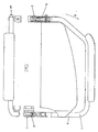
- the armrest 1 shown in Fig. 1 as an example of an attachment part of a wheelchair comprises a frame part 6, the a front and a rear fastening device 4, 5 connects with each other.
- the fasteners are in cylindrical receptacles 2 and 3 of the wheelchair insertable and locked in this position.
- the front fastening device 4 comprises a cylindrical element, one end portion 29 so is designed so that it is in a corresponding inner cylindrical Recording 3 of the wheelchair can be inserted.
- the other End region 30 is in one end of the frame 6 Inserted tube and by a transverse screw or rivet 31 rigidly connected to this.
- a circulating radial projection on the cylindrical element forms one Stop for both the frame tube and the mount of the wheelchair.
- any suitable Connection type such as gluing, welding, form or frictional connection can be selected.
- the Fastening device can even be an integral part of the frame tube or with corresponding external or Internal threads to be screwed to this. Furthermore can the outer contour of both the frame tube and the cylindrical element can be chosen arbitrarily.
- a locking lever 7 is in the cylindrical element a transverse axis 8 rotatable or pivotable stored.
- the locking lever has at its lower end a locking hook 14 in one of the Locking position corresponding position laterally protrudes the outer periphery of the cylindrical member and in this position when inserted into the receptacle Armrest in an opening in the receptacle 3 or on the Engages lower edge of the receptacle and pulling out the Armrest prevented from taking up.
- the hook 14 In the In the unlocked position, the hook 14 is inside of the cylindrical element and does not hinder that Inserting it into the wheelchair holder.
- the lower front area 13 of the hook 14 slightly beveled so that the hook is the insertion of the Armrest leads into the receptacle and relieves and the hook at the same time in the direction of the unlocked position or is pressed into the cylindrical part.
- the upper end 11 of the locking lever 7 engages in one Groove or recess 11 in a push button 10th is formed and forms an actuating element with this.
- the push button is in a transverse bore 9 of the Fastening device inserted and guided therein.
- a coil spring 12 which preloaded the push button so that it from the Bore 9 in the cylindrical element or in the frame tube protrudes.
- the Locking lever when the push button is not pressed in preloaded the locking position.
- the Locking lever 14 By pressing the Button against the action of the spring 12 is the Locking lever 14 with an inner surface of the groove or Recess 11 brought into contact and within a certain angular range around the axis 8 in the Unlocked position pivoted.
- locking device described with a swiveling hook which is operated by a push button
- the rear fastening device 5 comprises two articulated with one another with a pivot axis 22 connected cylindrical elements 15 and 28.
- element 28 is the rear locking device 7-14 in one hollow cylindrical part added. That is flexible connected element or joint piece 15 is like that cylindrical element of the front fastening device with the frame tube 6 rigidly connected. So it can be like this screwed to the frame tube in a suitable manner, riveted, welded, etc.
- the cylindrical member 28 is like the cylindrical member the front attachment into one inner cylindrical receptacle 2 of the seat device insertable and also has a circumferential paragraph, which as Stop serves.
- the locking device 7-14 includes one Locking lever 19 on a transverse axis 21 is rotatably or pivotally mounted.
- the locking lever has a locking hook 24 at its lower end, the one corresponding to the locking position Position laterally over the outer circumference of the cylindrical Elements 28 protrudes and in the recording inserted armrest in an opening in the receptacle 2 or engages on the lower edge of the receptacle and pulling it out the armrest from the holder prevented.
- the hook 19 In the In the unlocked position, the hook 19 is inside of the cylindrical member 28 and so does not hinder that Inserting it into the wheelchair holder.
- the lower front area of the hook 24 be slightly chamfered so that the hook introducing the Armrest in the receptacle relieved and the hook is pressed simultaneously into the cylindrical part.
- Coil spring 20 inserted into a hole in the lever 19 that the lever is constantly in the direction of Locked position preloaded or pushes.
- tension spring can be used instead of a compression spring can also be used in a suitable manner attached tension spring can be used.
- one Contact surface 26 is provided, which when pivoting the Fastening device about the pivot axis 22 with a Actuating surface 25 can be brought into contact the joint piece 15 is located and thus together with this is pivotable and from a certain swivel angle Locking lever 19 from the locking position in the Unlocked position pivoted. In this position, the armrest can be removed be removed
- the actuating surface 25 is part of the joint piece 15 and is designed as a flat surface.
- the actuating surface can also be designed as a curved surface, which is continuously in contact with a contact surface of the locking lever 19 and moves this when the frame is pivoted about the pivot axis 22 into the unlocking position.
- the pivot axis and the actuating surface or contour are arranged vertically and that the locking device of the rear fastening device is unlocked when the armrest is pivoted sideways.
- the locking device to be released by hand can be provided at the rear end of the attachment, while the locking device actuated when pivoting is provided at the front end. 1 can also be laterally offset from one another. If, for example, a legrest is attached as an attachment, the receptacles or the corresponding attachment devices can also be arranged one above the other.
Landscapes
- Health & Medical Sciences (AREA)
- Life Sciences & Earth Sciences (AREA)
- Animal Behavior & Ethology (AREA)
- General Health & Medical Sciences (AREA)
- Public Health (AREA)
- Veterinary Medicine (AREA)
- Seats For Vehicles (AREA)
- Spinning Or Twisting Of Yarns (AREA)
- Gripping Jigs, Holding Jigs, And Positioning Jigs (AREA)
- Clamps And Clips (AREA)
- Domestic Plumbing Installations (AREA)
- Adornments (AREA)
- Clips For Writing Implements (AREA)
- Fittings On The Vehicle Exterior For Carrying Loads, And Devices For Holding Or Mounting Articles (AREA)
Description
Das An- und Abbauen bisheriger Anbauteile verlangt dem Benutzer oft erhebliche Geschicklichkeit und Kraft ab. Diese Fähigkeiten sind aber gerade bei den Personen, die derartige Einrichtungen benötigen, in der Regel eingeschränkt.
Gleichzeitig ist zum Lösen der zweiten Verriegelung nur eine geringe Kraft erforderlich, da das gesamte Anbauteil bei der Schwenkbewegung und dem Entriegeln der weiteren Verriegelung als Hebel wirkt.
Beim Anbau muß nur eine Befestigungsvorrichtung in das entsprechende Anbauteil eingesetzt werden. Die Befestigung der zweiten Befestigungsvorrichtung ist dadurch vereinfacht, daß das Anbauteil bei der Schwenkbewegung insgesamt gehalten und in Richtung auf die zweite Aufnahme geführt wird.
Ebenso ist es denkbar, daß die Schwenkachse sowie die Betätigungsfläche oder -kontur senkrecht angeordnet sind und die Entriegelung der Verriegelungseinrichtung der hinteren Befestigungsvorrichtung bei seitlicher Verschwenkung der Armlehne erfolgt. In weiteren, nicht dargestellten Abwandlungen kann die von Hand zu lösende Verriegelungseinrichtung am hinteren Ende des Anbauteils vorgesehen werden, während die beim Verschwenken betätigte Verriegelungseinrichtung am vorderen Ende vorgesehen ist. Die Befestigungsvorrichtungen können gemäß Fig. 1 auch seitlich zueinander versetzt sein. Wird als Anbauteil beispielsweise eine Beinstütze befestigt, können die Aufnahmen bzw. die entsprechenden Befestigungsvorrichtungen auch übereinander angeordnet sein.
Claims (10)
- Anbauteil, insbesondere Armlehne zur lösbaren Befestigung an einer Sitzeinrichtung, insbesondere einem Rollstuhl, mit
einer ersten und einer zweiten Befestigungsvorrichtung (5,4), die mittels eines Rahmens (6) miteinander verbundenen sind und die jeweils eine Verriegelungseinrichtung (19-23,7-14) zur formschlüssigen lösbaren Verriegelung des Anbauteils an geeigneten Aufnahmen (3,2) der Sitzeinrichtung aufweisen, wobei die Verriegelungseinrichtung (7-14) der zweiten Befestigungsvorrichtung (4) von Hand betätigbar und lösbar ist und die Verriegelungseinrichtung (19-23) der ersten Befestigungsvorrichtung (5) durch Verschwenken des Rahmens (6) um eine Schwenkachse (22) betätigbar ist,
dadurch gekennzeichnet, dass
die Schwenkachse (22) ein Bestandteil der Verriegelungseinrichtung (19-23) der ersten Befestigungsvorrichtung (5) ist. - Anbauteil gemäß Anspruch 1, wobei die Verriegelungseinrichtung (19-23) der ersten Befestigungsvorrichtung (5) nach dem Entriegeln durch Verschwenken des Rahmens (5) zusammen mit diesem von der Aufnahme der Sitzeinrichtung abnehmbar ist.
- Anbauteil gemäß Anspruch 1 oder 2, wobei die Verriegelungseinrichtung (19-23) der ersten Befestigungsvorrichtung (5) einen Verriegelungshebel (19) umfaßt, der beim Verschwenken des Rahmens (6) um die Schwenkachse (22) mit einem Betätigungselement (25) zusammenwirkt und dabei betätigt wird, wobei das Betätigungselement (25) Bestandteil des Rahmens (6) des Anbauteils bzw. der ersten Befestigungsvorrichtung (5) ist.
- Anbauteil gemäß Anspruch 3, wobei der Verriegelungshebel (19) an einer Achse (21) schwenkbar gelagert ist und dessen eines Ende einen Verriegelungsabschnitt (24) aufweist und dessen anderes Ende bei der Schwenkbewegung des Rahmens (6) um die Schwenkachse (22) mit dem Betätigungselement (25) zusammenwirkt und dabei den Verriegelungshebel (19) um die Achse (21) in eine Entriegelungsstellung zu verschwenken vermag.
- Anbauteil gemäß Anspruch 4, wobei das Betätigungselement (25) so angeordnet ist, dass es den Verriegelungshebel (19) erst nach Verschwenken des Rahmens (6) über einen vorgegebenen Winkelbereich in die Entriegelungsstellung zu verschwenken vermag.
- Anbauteil gemäß Anspruch 3, 4 oder 5, wobei das Betätigungselement (25) durch eine Betätigungsfläche gebildet ist, die bei der Verschwenkung des Rahmens (6) um die Schwenkachse (22) ebenfalls um diese Schwenkachse (22) verschwenkbar ist.
- Anbauteil gemäß einem der vorstehenden Ansprüche, wobei die erste Befestigungseinrichtung (5) zwei mittels der Schwenkachse (22) gelenkig miteinander verbundene Elemente (15,28) aufweist, wobei in einem der Elemente die Verriegelungseinrichtung (19-23) aufgenommen ist und dieses Element (28) in eine zylindrische Aufnahme der Sitzeinrichtung einsteckbar ist und wobei das andere Element (15) mit dem Rahmen (6) des Anbauteils verbunden ist.
- Anbauteil gemäß einem der vorstehenden Ansprüche, wobei die Verriegelungseinrichtung (7-14) der zweiten Befestigungsvorrichtung (4) einen an einer Achse (8) schwenkbar gelagerten Verriegelungshebel (7) umfaßt, dessen eines Ende einen Verriegelungsabschnitt (14) aufweist und dessen anderes Ende mit einem von Hand betätigbaren Betätigungselement (10,11) zusammenwirkt und dabei um die Achse (8) in eine Entriegelungsstellung'verschwenkbar ist.
- Anbauteil gemäß einem der vorstehenden Ansprüche, wobei die zweite Befestigungseinrichtung (4) ein Element aufweist, in dem die zweite Verriegelungseinrichtung (7-14) aufgenommen ist und dessen einer Endbereich (30) mit dem Rahmen (6) verbunden ist und dessen anderer Endbereich (29) in eine zylindrische Aufnahme der Sitzeinrichtung einsteckbar ist.
- Anbauteil gemäß einem der vorstehenden Ansprüche, wobei die erste und/oder die zweite Verriegelungseinrichtung mittels einer Feder (20,12) in eine Verriegelungsstellung vorbelastet ist/sind.
Priority Applications (6)
| Application Number | Priority Date | Filing Date | Title |
|---|---|---|---|
| AT96115926T ATE240708T1 (de) | 1996-10-04 | 1996-10-04 | Anbauteil zur lösbaren befestigung an sitzeinrichtungen |
| DE59610458T DE59610458D1 (de) | 1996-10-04 | 1996-10-04 | Anbauteil zur lösbaren Befestigung an Sitzeinrichtungen |
| DK96115926T DK0834298T3 (da) | 1996-10-04 | 1996-10-04 | Tilbehørsdel til løsbar fastgøring på siddeindretninger |
| EP96115926A EP0834298B1 (de) | 1996-10-04 | 1996-10-04 | Anbauteil zur lösbaren Befestigung an Sitzeinrichtungen |
| NO970202A NO970202L (no) | 1996-10-04 | 1997-01-16 | Påbygningsdel for lösbar fastgjöring på en sitteinnretning |
| TW086110908A TW342332B (en) | 1996-10-04 | 1997-07-30 | Attachment detachably mounted to a seat |
Applications Claiming Priority (1)
| Application Number | Priority Date | Filing Date | Title |
|---|---|---|---|
| EP96115926A EP0834298B1 (de) | 1996-10-04 | 1996-10-04 | Anbauteil zur lösbaren Befestigung an Sitzeinrichtungen |
Publications (2)
| Publication Number | Publication Date |
|---|---|
| EP0834298A1 EP0834298A1 (de) | 1998-04-08 |
| EP0834298B1 true EP0834298B1 (de) | 2003-05-21 |
Family
ID=8223267
Family Applications (1)
| Application Number | Title | Priority Date | Filing Date |
|---|---|---|---|
| EP96115926A Expired - Lifetime EP0834298B1 (de) | 1996-10-04 | 1996-10-04 | Anbauteil zur lösbaren Befestigung an Sitzeinrichtungen |
Country Status (6)
| Country | Link |
|---|---|
| EP (1) | EP0834298B1 (de) |
| AT (1) | ATE240708T1 (de) |
| DE (1) | DE59610458D1 (de) |
| DK (1) | DK0834298T3 (de) |
| NO (1) | NO970202L (de) |
| TW (1) | TW342332B (de) |
Cited By (1)
| Publication number | Priority date | Publication date | Assignee | Title |
|---|---|---|---|---|
| EP4203881A4 (de) * | 2020-08-27 | 2024-10-09 | Pride Mobility Products Corporation | Verstellbare armlehne für rollstuhl |
Families Citing this family (2)
| Publication number | Priority date | Publication date | Assignee | Title |
|---|---|---|---|---|
| CN103800147A (zh) * | 2012-11-14 | 2014-05-21 | 镇江艾康医疗器械有限公司 | 一种改进型轮椅可拆扶手 |
| CN106691726B (zh) * | 2015-08-20 | 2019-01-22 | 吉芮医疗器械(上海)有限公司 | 轮椅车扶手锁定装置 |
Family Cites Families (4)
| Publication number | Priority date | Publication date | Assignee | Title |
|---|---|---|---|---|
| GB2047528A (en) * | 1979-04-03 | 1980-12-03 | Vessa Ltd | Wheelchair having a detachable armrest |
| US4768797A (en) * | 1987-01-28 | 1988-09-06 | Everest & Jennings | Folding wheelchair having adjustable wheels and armrests |
| US5462380A (en) * | 1994-11-10 | 1995-10-31 | Labac Systems, Inc. | Detent |
| US5544940A (en) * | 1994-12-12 | 1996-08-13 | Quickie Designs Inc. | Pivotal rear latch assembly for an armrest apparatus for a wheelchair |
-
1996
- 1996-10-04 AT AT96115926T patent/ATE240708T1/de not_active IP Right Cessation
- 1996-10-04 EP EP96115926A patent/EP0834298B1/de not_active Expired - Lifetime
- 1996-10-04 DE DE59610458T patent/DE59610458D1/de not_active Expired - Fee Related
- 1996-10-04 DK DK96115926T patent/DK0834298T3/da active
-
1997
- 1997-01-16 NO NO970202A patent/NO970202L/no unknown
- 1997-07-30 TW TW086110908A patent/TW342332B/zh active
Cited By (1)
| Publication number | Priority date | Publication date | Assignee | Title |
|---|---|---|---|---|
| EP4203881A4 (de) * | 2020-08-27 | 2024-10-09 | Pride Mobility Products Corporation | Verstellbare armlehne für rollstuhl |
Also Published As
| Publication number | Publication date |
|---|---|
| NO970202L (no) | 1998-04-06 |
| TW342332B (en) | 1998-10-11 |
| NO970202D0 (no) | 1997-01-16 |
| EP0834298A1 (de) | 1998-04-08 |
| DK0834298T3 (da) | 2003-09-15 |
| ATE240708T1 (de) | 2003-06-15 |
| DE59610458D1 (de) | 2003-06-26 |
Similar Documents
| Publication | Publication Date | Title |
|---|---|---|
| DE68913791T2 (de) | Rahmen. | |
| DE69212482T2 (de) | Türschlossanordnung mit verschliessbarem Handgriff für Behinderte | |
| DE60021452T2 (de) | Blockiervorrichtung | |
| EP2101706B1 (de) | Lösbare anbringung eines zubehörs an einem operationstisch | |
| DE60207485T2 (de) | Verriegelbarer Türgriff mit zwei Schlössern | |
| DE2931107A1 (de) | Fusstuetzenverriegelung fuer einen rollstuhl | |
| DE3804199C2 (de) | ||
| EP0526775A1 (de) | Halterung für eine Handbrause | |
| DE102015101829A1 (de) | Spannklaue zur Anbringung an einer Gleitschiene eines Operationstisches | |
| EP2371253A2 (de) | Toilettensitz | |
| EP2272437A2 (de) | Chirurgisches Spreizinstrument | |
| DE4323093A1 (de) | Chirurgische Zange | |
| EP0754829A1 (de) | Vorrichtung zum Anschliessen eines Schwenkteils, beispielsweise einer Fahrzeughaube an einen Körper, beispielsweise an einen Fahrzeugrahmen | |
| DE2346323C2 (de) | Handstück für ein drehbares Werkzeug für zahnärztliche oder chirurgische Zwecke | |
| DE19928729B4 (de) | Fenstergriffschloß | |
| EP0834298A1 (de) | Anbauteil zur lösbaren Befestigung an Sitzeinrichtungen | |
| DE3628911C2 (de) | ||
| DE69107356T2 (de) | In der Gliedmassenstreckstellung verriegelbares Gelenk für eine Untergliedmassenorthese. | |
| DE10243135A1 (de) | Ausbaubarer Sitz für ein Kraftfahrzeug, der automatisch gekippt und baulängenrichtig montiert werden kann | |
| EP0207916A2 (de) | Beschlag, insbesondere für Bürostühle | |
| DE102021125710B3 (de) | Kapp- und Zugsäge | |
| DE29518434U1 (de) | Handstück für das distale Ende eines Laserlicht führenden Lichtleiters | |
| DE3626298C1 (en) | Device for the releasable connection of a pram/push-chair body to a pram/push-chair frame | |
| DE69320077T2 (de) | Kraftfahrzeug-Türschloss mit einer Vorrichtung, zur Verhinderung jeglicher Betätigung des Sicherheitshebels | |
| DE102004056042A1 (de) | Fenster, Tür oder dergleichen mit einer Eckumlenkung |
Legal Events
| Date | Code | Title | Description |
|---|---|---|---|
| PUAI | Public reference made under article 153(3) epc to a published international application that has entered the european phase |
Free format text: ORIGINAL CODE: 0009012 |
|
| AK | Designated contracting states |
Kind code of ref document: A1 Designated state(s): AT BE CH DE DK ES FI FR GB IT LI NL SE |
|
| EL | Fr: translation of claims filed | ||
| GBC | Gb: translation of claims filed (gb section 78(7)/1977) | ||
| TCNL | Nl: translation of patent claims filed | ||
| 17P | Request for examination filed |
Effective date: 19980518 |
|
| AKX | Designation fees paid |
Free format text: AT BE CH DE DK ES FI FR GB IT LI NL SE |
|
| RBV | Designated contracting states (corrected) |
Designated state(s): AT BE CH DE DK ES FI FR GB IT LI NL SE |
|
| 17Q | First examination report despatched |
Effective date: 20000810 |
|
| GRAH | Despatch of communication of intention to grant a patent |
Free format text: ORIGINAL CODE: EPIDOS IGRA |
|
| GRAH | Despatch of communication of intention to grant a patent |
Free format text: ORIGINAL CODE: EPIDOS IGRA |
|
| GRAA | (expected) grant |
Free format text: ORIGINAL CODE: 0009210 |
|
| AK | Designated contracting states |
Designated state(s): AT BE CH DE DK ES FI FR GB IT LI NL SE |
|
| REG | Reference to a national code |
Ref country code: GB Ref legal event code: FG4D Free format text: NOT ENGLISH |
|
| REG | Reference to a national code |
Ref country code: SE Ref legal event code: TRGR |
|
| REG | Reference to a national code |
Ref country code: CH Ref legal event code: EP |
|
| GBT | Gb: translation of ep patent filed (gb section 77(6)(a)/1977) |
Effective date: 20030521 |
|
| REG | Reference to a national code |
Ref country code: CH Ref legal event code: NV Representative=s name: DR. LUSUARDI AG |
|
| REF | Corresponds to: |
Ref document number: 59610458 Country of ref document: DE Date of ref document: 20030626 Kind code of ref document: P |
|
| PG25 | Lapsed in a contracting state [announced via postgrant information from national office to epo] |
Ref country code: ES Free format text: LAPSE BECAUSE OF FAILURE TO SUBMIT A TRANSLATION OF THE DESCRIPTION OR TO PAY THE FEE WITHIN THE PRESCRIBED TIME-LIMIT Effective date: 20030901 |
|
| REG | Reference to a national code |
Ref country code: DK Ref legal event code: T3 |
|
| ET | Fr: translation filed | ||
| PLBE | No opposition filed within time limit |
Free format text: ORIGINAL CODE: 0009261 |
|
| STAA | Information on the status of an ep patent application or granted ep patent |
Free format text: STATUS: NO OPPOSITION FILED WITHIN TIME LIMIT |
|
| 26N | No opposition filed |
Effective date: 20040224 |
|
| PGFP | Annual fee paid to national office [announced via postgrant information from national office to epo] |
Ref country code: GB Payment date: 20050923 Year of fee payment: 10 |
|
| PGFP | Annual fee paid to national office [announced via postgrant information from national office to epo] |
Ref country code: NL Payment date: 20051018 Year of fee payment: 10 |
|
| PGFP | Annual fee paid to national office [announced via postgrant information from national office to epo] |
Ref country code: FR Payment date: 20051019 Year of fee payment: 10 |
|
| PGFP | Annual fee paid to national office [announced via postgrant information from national office to epo] |
Ref country code: FI Payment date: 20051021 Year of fee payment: 10 |
|
| PGFP | Annual fee paid to national office [announced via postgrant information from national office to epo] |
Ref country code: SE Payment date: 20051024 Year of fee payment: 10 Ref country code: CH Payment date: 20051024 Year of fee payment: 10 Ref country code: BE Payment date: 20051024 Year of fee payment: 10 Ref country code: AT Payment date: 20051024 Year of fee payment: 10 |
|
| PGFP | Annual fee paid to national office [announced via postgrant information from national office to epo] |
Ref country code: DK Payment date: 20051026 Year of fee payment: 10 |
|
| PGFP | Annual fee paid to national office [announced via postgrant information from national office to epo] |
Ref country code: DE Payment date: 20051229 Year of fee payment: 10 |
|
| PG25 | Lapsed in a contracting state [announced via postgrant information from national office to epo] |
Ref country code: FI Free format text: LAPSE BECAUSE OF NON-PAYMENT OF DUE FEES Effective date: 20061004 Ref country code: AT Free format text: LAPSE BECAUSE OF NON-PAYMENT OF DUE FEES Effective date: 20061004 |
|
| PG25 | Lapsed in a contracting state [announced via postgrant information from national office to epo] |
Ref country code: SE Free format text: LAPSE BECAUSE OF NON-PAYMENT OF DUE FEES Effective date: 20061005 |
|
| PG25 | Lapsed in a contracting state [announced via postgrant information from national office to epo] |
Ref country code: LI Free format text: LAPSE BECAUSE OF NON-PAYMENT OF DUE FEES Effective date: 20061031 Ref country code: DK Free format text: LAPSE BECAUSE OF NON-PAYMENT OF DUE FEES Effective date: 20061031 Ref country code: CH Free format text: LAPSE BECAUSE OF NON-PAYMENT OF DUE FEES Effective date: 20061031 |
|
| PGFP | Annual fee paid to national office [announced via postgrant information from national office to epo] |
Ref country code: IT Payment date: 20061031 Year of fee payment: 11 |
|
| PG25 | Lapsed in a contracting state [announced via postgrant information from national office to epo] |
Ref country code: NL Free format text: LAPSE BECAUSE OF NON-PAYMENT OF DUE FEES Effective date: 20070501 Ref country code: DE Free format text: LAPSE BECAUSE OF NON-PAYMENT OF DUE FEES Effective date: 20070501 |
|
| REG | Reference to a national code |
Ref country code: CH Ref legal event code: PL |
|
| EUG | Se: european patent has lapsed | ||
| GBPC | Gb: european patent ceased through non-payment of renewal fee |
Effective date: 20061004 |
|
| NLV4 | Nl: lapsed or anulled due to non-payment of the annual fee |
Effective date: 20070501 |
|
| REG | Reference to a national code |
Ref country code: FR Ref legal event code: ST Effective date: 20070629 |
|
| PG25 | Lapsed in a contracting state [announced via postgrant information from national office to epo] |
Ref country code: GB Free format text: LAPSE BECAUSE OF NON-PAYMENT OF DUE FEES Effective date: 20061004 |
|
| BERE | Be: lapsed |
Owner name: *ORTOPEDIA G.M.B.H. Effective date: 20061031 |
|
| PG25 | Lapsed in a contracting state [announced via postgrant information from national office to epo] |
Ref country code: FR Free format text: LAPSE BECAUSE OF NON-PAYMENT OF DUE FEES Effective date: 20061031 |
|
| PG25 | Lapsed in a contracting state [announced via postgrant information from national office to epo] |
Ref country code: IT Free format text: LAPSE BECAUSE OF NON-PAYMENT OF DUE FEES Effective date: 20071004 Ref country code: BE Free format text: LAPSE BECAUSE OF FAILURE TO SUBMIT A TRANSLATION OF THE DESCRIPTION OR TO PAY THE FEE WITHIN THE PRESCRIBED TIME-LIMIT Effective date: 20061031 |