EP0832714B1 - Pumpstation für Späne enthaltende Kühl- und Schmiermittel - Google Patents
Pumpstation für Späne enthaltende Kühl- und Schmiermittel Download PDFInfo
- Publication number
- EP0832714B1 EP0832714B1 EP97116202A EP97116202A EP0832714B1 EP 0832714 B1 EP0832714 B1 EP 0832714B1 EP 97116202 A EP97116202 A EP 97116202A EP 97116202 A EP97116202 A EP 97116202A EP 0832714 B1 EP0832714 B1 EP 0832714B1
- Authority
- EP
- European Patent Office
- Prior art keywords
- coolants
- chips
- lubricants
- collecting tank
- pump
- Prior art date
- Legal status (The legal status is an assumption and is not a legal conclusion. Google has not performed a legal analysis and makes no representation as to the accuracy of the status listed.)
- Expired - Lifetime
Links
- 239000002826 coolant Substances 0.000 title claims abstract description 32
- 239000000314 lubricant Substances 0.000 title claims description 32
- 238000005086 pumping Methods 0.000 claims abstract description 18
- 238000011010 flushing procedure Methods 0.000 claims description 3
- 230000007704 transition Effects 0.000 claims description 2
- 239000004020 conductor Substances 0.000 claims 6
- 239000012530 fluid Substances 0.000 abstract 3
- 239000002699 waste material Substances 0.000 abstract 1
- 238000001816 cooling Methods 0.000 description 3
- 238000009825 accumulation Methods 0.000 description 2
- 239000007788 liquid Substances 0.000 description 2
- 230000001174 ascending effect Effects 0.000 description 1
- 230000015572 biosynthetic process Effects 0.000 description 1
- 230000000694 effects Effects 0.000 description 1
- 230000005484 gravity Effects 0.000 description 1
- 239000003673 groundwater Substances 0.000 description 1
- 238000003754 machining Methods 0.000 description 1
- 238000004519 manufacturing process Methods 0.000 description 1
- 239000000203 mixture Substances 0.000 description 1
- 230000000717 retained effect Effects 0.000 description 1
- 239000002689 soil Substances 0.000 description 1
Images
Classifications
-
- B—PERFORMING OPERATIONS; TRANSPORTING
- B23—MACHINE TOOLS; METAL-WORKING NOT OTHERWISE PROVIDED FOR
- B23Q—DETAILS, COMPONENTS, OR ACCESSORIES FOR MACHINE TOOLS, e.g. ARRANGEMENTS FOR COPYING OR CONTROLLING; MACHINE TOOLS IN GENERAL CHARACTERISED BY THE CONSTRUCTION OF PARTICULAR DETAILS OR COMPONENTS; COMBINATIONS OR ASSOCIATIONS OF METAL-WORKING MACHINES, NOT DIRECTED TO A PARTICULAR RESULT
- B23Q11/00—Accessories fitted to machine tools for keeping tools or parts of the machine in good working condition or for cooling work; Safety devices specially combined with or arranged in, or specially adapted for use in connection with, machine tools
- B23Q11/10—Arrangements for cooling or lubricating tools or work
- B23Q11/1069—Filtration systems specially adapted for cutting liquids
-
- Y—GENERAL TAGGING OF NEW TECHNOLOGICAL DEVELOPMENTS; GENERAL TAGGING OF CROSS-SECTIONAL TECHNOLOGIES SPANNING OVER SEVERAL SECTIONS OF THE IPC; TECHNICAL SUBJECTS COVERED BY FORMER USPC CROSS-REFERENCE ART COLLECTIONS [XRACs] AND DIGESTS
- Y10—TECHNICAL SUBJECTS COVERED BY FORMER USPC
- Y10T—TECHNICAL SUBJECTS COVERED BY FORMER US CLASSIFICATION
- Y10T409/00—Gear cutting, milling, or planing
- Y10T409/30—Milling
- Y10T409/304088—Milling with means to remove chip
-
- Y—GENERAL TAGGING OF NEW TECHNOLOGICAL DEVELOPMENTS; GENERAL TAGGING OF CROSS-SECTIONAL TECHNOLOGIES SPANNING OVER SEVERAL SECTIONS OF THE IPC; TECHNICAL SUBJECTS COVERED BY FORMER USPC CROSS-REFERENCE ART COLLECTIONS [XRACs] AND DIGESTS
- Y10—TECHNICAL SUBJECTS COVERED BY FORMER USPC
- Y10T—TECHNICAL SUBJECTS COVERED BY FORMER US CLASSIFICATION
- Y10T409/00—Gear cutting, milling, or planing
- Y10T409/40—Broaching
- Y10T409/401225—Broaching with product handling means
- Y10T409/40175—Chip removal means
Definitions
- the invention relates to a pumping station for coolants and lubricants containing chips at least one feed line.
- This opens into a collection container, the at least one Pump is assigned.
- the pressure side of the pump is connected to a discharge line.
- the feed line has an incline in the collecting container line branch for the coolants and lubricants after a slope above of the collecting container opening line branch for the chips.
- they are Mouths of the line branches are arranged so that the one in the collecting container falling chip flow onto the coolant and lubricant flow flowing into the collection container meets.
- Such well-known pumping stations are used for chip-removing processing chips from workpieces together with coolants and lubricants from the Processing machines, for example via pipelines, so that elsewhere The coolants and lubricants can be separated from the chips.
- a pump station of the type described in the introduction is, for example, from EP 0 518 095 A1 known. Due to the separate supply of coolants and lubricants via two line branches on the one hand and the chips on the other hand, each line branch can be optimal adapt to the goods to be transported. This is enough for those who transport the coolants and lubricants Line branch a slight slope in the direction of the collecting tank, which is continues over the tank bottom to the pump suction side. To get the chips through for that provided ascending and branching pipe branch opening above the collecting container transport, a conventionally trained scraper conveyor can be used.
- a disadvantage of this known pump station is the fact that the design of the Sump of the suction pump is difficult because of the fluctuation range between the minimum and maximum volume flow is large.
- a pump station is already known from EP 0 518 095, in which shredded chips pass through the flow of the coolants and lubricants are fed to a collecting container, the Soil has a slight slope. The mixture of coolants and lubricants as well In this way, chips are transported into the deepest area of the tank bottom, which is a pump assigned.
- the chips are rotated by a drive displaced reamer is forced to below the suction opening of the pump.
- the scraper lies on the bottom of the tank with clearing arms on. But there can still be chips between the top of the container bottom and reach the underside of the clearing arm so that the clearing arms jam with the bottom of the container.
- additional means are provided in the known device, lifting the scraper or lifting the scraper arms from the bottom of the container should enable.
- the invention has for its object a pumping station of the type described above to be designed so that regardless of the volume flow of the chips to be pumped containing liquid a safe suction of the liquid is guaranteed.
- the suction side of the pump located lower so that its suction side is in a Cross-section small, deepest area of the collection container is located while the suction side the higher-lying pump, for example (also laterally) can be arranged so offset, that the cross section of the collecting container can widen.
- Such an extension of the Cross-section from bottom to top is advantageous because of the narrowing of the cross-section in the opposite direction, safe chip transport into the suction area of the lower one Pump takes place, even if there is only a very small volume flow.
- the pumps are preferably switched so that the suction side is lower Pump is designed for a power that contains the minimum volume flow of chips Corresponds to coolants and lubricants.
- the volume flow increases and increases the content in the collection container above a certain normal level can be automatically As a precaution, switch on the second pump, which is located higher on the suction side, until the normal level is restored.
- the line branch that feeds the chips is one Scraper conveyor equipped with which the chips a feed hopper one Chip breaker arranged above the collecting container can be fed.
- the outlet opening of the chip breaker preferably opens above one in the pump direction inclined bottom part of the collecting container, the one that supplies the coolants and lubricants Line branch with its sole merges into this bottom part.
- a further embodiment of the invention provides that in the transition area between the mouth of the coolant and lubricant supply line and the adjoining bottom part with a load of cleaned coolants and lubricants Flush line opens.
- the mouth of the flushing line can be equipped with a valve with which the in Circulated coolant and lubricant volume flow between zero and can regulate a maximum.
- At least all of them are outside the range arranged on the pump suction side to a bottom defining a container sump horizontal bottom part aligned inclined.
- the inclination of the bottom parts of the collecting container in the direction of the container sump can be so be slight that an above-ground arrangement of the pumping station is less overall Overall height is possible and the tank bottom design nevertheless ensures that all Components in the collection container get into the suction area of the pump.
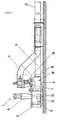
- a line branch 3 is coaxial with the feed line 2 at a distance in front of the pump station 1 connected, which runs like the feed line 2 with a slight slope. Furthermore is on the feed line 2 likewise has a line branch 4 at a distance from the pump station 1 connected, which rises in the direction of pump station 1. While over line branch 3 Coolants and lubricants flow to the pump station 1 due to a natural gradient chips via the line branch 4, for example by means of a conventional scraper conveyor fed to the pumping station 1.
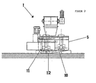
- the pumping station 1 essentially comprises a collecting container 5, two pumps 6 and one Chip breaker 7.
- the collecting container 5 has a bottom made of differently inclined bottom parts 8, 9, 10 and 11 and provided with a horizontal floor area 12. From the horizontal Floor area 12 from the remaining floor parts 8, 9, 10 and 11 rise slightly and allow thus the formation of a container sump 13.
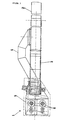
- the chip breaker 7 is acted on by a hopper 14, which is under a Outlet opening of the line branch 4 is arranged.
- the chip breaker outlet 7 is located above the base part 8 inclined in the direction of the pumps 6.
- the coolant and lubricant-carrying line branch 3 goes with its sole 15 into the bottom part 8 over. Crushed chips emerging from the chip breaker 7 thus meet the Flow of the coolants and lubricants flowing over the base part 8. The latter tear continuously the shredded chips with, so that an accumulation of chips on the bottom part 8 avoided becomes.
- a flushing line 16 is provided in the upper region of the base part 8, which can be charged with a partial flow of already cleaned coolants and lubricants and via one or more outlet nozzles each a delivery jet for any chip accumulation aligns so that they are inevitably rinsed in the container sump.
Landscapes
- Engineering & Computer Science (AREA)
- Mechanical Engineering (AREA)
- Auxiliary Devices For Machine Tools (AREA)
- Cooling Or The Like Of Electrical Apparatus (AREA)
- Lubricants (AREA)
- Jet Pumps And Other Pumps (AREA)
Description
- Figur 1
- eine Längsseitenansicht
- Figur 2
- eine Querseitenansicht
- Figur 3
- einen Grundriß
Claims (5)
- Pumpstation für Späne enthaltende Kühl- und Schmierstoffe mit mindestens einer Zuführleitung, die in einen Sammelbehälter mündet, dem mindestens eine Pumpe zugeordnet ist, deren Druckseite mit einer Abführleitung in Verbindung steht, wobei die Zuführleitung (2) zusätzlich zu einem mit Gefälle in den Sammelbehälter (5) mündenden Leitungszweig (3) für die Kühl- und Schmierstoffe einen nach einer Steigung oberhalb des Sammelbehälters (5) mündenden Leitungszweig (4) für die Späne aufweist und die Mündungen der Leitungszweige (3, 4) so zueinander angeordnet sind, daß der in den Sammelbehälter (5) fallende Spänestrom auf den in den Sammelbehälter (5) fließenden Kühl- und Schmierstoffstrom trifft, dadurch gekennzeichnet, daß im Sammelbehälter (5) zwei Pumpen (6) angeordnet sind, deren saugseitige Öffnungen auf unterschiedlichem Niveau liegen.
- Pumpstation nach Anspruch 1, dadurch gekennzeichnet, daß der die Späne führende Leitungszweig (4) mit einer Kratzfördereinrichtung ausgestattet ist, mit der die Späne einem Beschickungstrichter (14) eines oberhalb des Sammelbehälters (5) angeordneten Spänebrechers (7) zuführbar sind.
- Pumpstation nach Anspruch 2, dadurch gekennzeichnet, daß eine Auslaßöffnung des Spänebrechers (7) oberhalb eines in Pumpenrichtung geneigten Bodenteils (8) des Sammelbehälters (5) mündet und daß der die Kühl- und Schmierstoffe zuführende Leitungszweig (3) mit seiner Sohle (15) in dieses Bodenteil (8) übergeht.
- Pumpstation nach einem der Ansprüche 1 bis 3, dadurch gekennzeichnet, daß im Übergangsbereich zwischen der Mündung des Kühl- und Schmierstoffe zuführenden Leitungszweiges (3) und dem sich anschließenden Bodenteil (8) eine mit gereinigten Kühl- und Schmierstoffen beaufschlagbare Spülleitung (16) mündet.
- Pumpstation nach einem der Ansprüche 1 bis 4, dadurch gekennzeichnet, daß mindestens alle außerhalb des Bereichs der Pumpensaugseite angeordneten Bodenteile (8, 9, 10, 11) zu einem einen Behältersumpf (13) definierenden Bodenbereich (12) geneigt ausgerichtet sind.
Applications Claiming Priority (2)
| Application Number | Priority Date | Filing Date | Title |
|---|---|---|---|
| DE29616893U DE29616893U1 (de) | 1996-09-27 | 1996-09-27 | Pumpstation für Späne enthaltende Kühl- und Schmierstoffe |
| DE29616893U | 1996-09-27 |
Publications (2)
| Publication Number | Publication Date |
|---|---|
| EP0832714A1 EP0832714A1 (de) | 1998-04-01 |
| EP0832714B1 true EP0832714B1 (de) | 2001-11-28 |
Family
ID=8029857
Family Applications (1)
| Application Number | Title | Priority Date | Filing Date |
|---|---|---|---|
| EP97116202A Expired - Lifetime EP0832714B1 (de) | 1996-09-27 | 1997-09-18 | Pumpstation für Späne enthaltende Kühl- und Schmiermittel |
Country Status (6)
| Country | Link |
|---|---|
| US (1) | US6126099A (de) |
| EP (1) | EP0832714B1 (de) |
| AT (1) | ATE209554T1 (de) |
| BR (1) | BR9704905A (de) |
| DE (2) | DE29616893U1 (de) |
| ES (1) | ES2164973T3 (de) |
Families Citing this family (32)
| Publication number | Priority date | Publication date | Assignee | Title |
|---|---|---|---|---|
| DE19704859A1 (de) * | 1997-02-10 | 1998-08-13 | Mann & Hummel Filter | Aufbereitungseinrichtung für Späne enthaltende Kühl- und Schmierstoffe |
| US6125883A (en) * | 1998-01-09 | 2000-10-03 | Henry Filters, Inc. | Floor mounted double containment low profile sump pump assembly |
| AT411161B (de) * | 1999-09-22 | 2003-10-27 | Bacher Helmut | Verfahren und vorrichtung zum recyclen von pet-gut |
| FR2803775B1 (fr) * | 2000-01-18 | 2004-01-02 | Omsat France | Dispositif de broyage et de pompage d'un melange de copeaux metalliques et de fluide de coupe |
| JP2003117765A (ja) * | 2001-10-03 | 2003-04-23 | Toshiba Mach Co Ltd | 数値制御工作機械の運転制御方法および数値制御工作機械 |
| US7146991B2 (en) | 2002-01-23 | 2006-12-12 | Cinetic Automation Corporation | Parts washer system |
| US6742731B2 (en) * | 2002-03-19 | 2004-06-01 | Inter-Source Recovery Systems | System and method of shredding wet chips in a flume |
| DE10244012A1 (de) * | 2002-09-21 | 2004-04-01 | Mann + Hummel Gmbh | Aufbereitungseinrichtung für Späne enthaltende Kühl- und Schmiermittel |
| US7467755B2 (en) * | 2003-07-01 | 2008-12-23 | Inter-Source Recovery Systems, Inc. | Parts separator apparatus and method of shredding |
| US7028935B2 (en) | 2003-07-01 | 2006-04-18 | Inter-Source Recovery Systems, Inc. | Apparatus and method for shredding wet chip materials |
| US7338565B2 (en) * | 2003-08-21 | 2008-03-04 | Cinetic Automation Corporation | Housingless washer |
| US7353832B2 (en) * | 2003-08-21 | 2008-04-08 | Cinetic Automation Corporation | Housingless washer |
| US7380736B2 (en) * | 2005-05-04 | 2008-06-03 | Inter-Source Systems, Inc. | In-line shredder apparatus and method for shredding materials |
| US7410569B1 (en) * | 2005-11-18 | 2008-08-12 | Turhan A. Tilev | Filtration system for metalworking fluids |
| DE502005002857D1 (de) * | 2005-11-26 | 2008-03-27 | Cross Hueller Gmbh | Spanbrecher mit Absaugvorrichtung |
| WO2009100314A2 (en) * | 2008-02-07 | 2009-08-13 | Miller Edward B | Conveyor debris washing apparatus and methods |
| US9968944B2 (en) | 2013-03-15 | 2018-05-15 | Inter-Source Recovery Systems | Parts separator |
| CN106217113A (zh) * | 2016-08-22 | 2016-12-14 | 张民胜 | 一种数控机床自动排屑的装置 |
| US12179299B2 (en) * | 2018-08-07 | 2024-12-31 | Illinois Tool Works Inc. | Machine tool with recirculating coolant filtration system |
| CN109372827B (zh) * | 2018-10-09 | 2020-05-05 | 泰州市博泰电子有限公司 | 一种具有安全性的液压泵站 |
| US10966338B1 (en) | 2020-03-11 | 2021-03-30 | Peter C. Salmon | Densely packed electronic systems |
| US12302497B2 (en) | 2020-03-11 | 2025-05-13 | Peter C. Salmon | Densely packed electronic systems |
| US11393807B2 (en) | 2020-03-11 | 2022-07-19 | Peter C. Salmon | Densely packed electronic systems |
| US11546991B2 (en) | 2020-03-11 | 2023-01-03 | Peter C. Salmon | Densely packed electronic systems |
| JP7406426B2 (ja) * | 2020-03-26 | 2023-12-27 | 株式会社Fuji | 工作機械 |
| US12376254B2 (en) | 2022-02-25 | 2025-07-29 | Peter C. Salmon | Water cooled server |
| US11445640B1 (en) | 2022-02-25 | 2022-09-13 | Peter C. Salmon | Water cooled server |
| US11523543B1 (en) | 2022-02-25 | 2022-12-06 | Peter C. Salmon | Water cooled server |
| US12628317B2 (en) | 2022-08-18 | 2026-05-12 | Peter C. Salmon | Zettascale supercomputer |
| US12136576B1 (en) | 2023-06-22 | 2024-11-05 | Peter C. Salmon | Microelectronic module |
| US12469754B2 (en) | 2023-09-07 | 2025-11-11 | Peter C. Salmon | Hermetic microelectronic module using a sheath |
| US12255122B1 (en) | 2023-12-13 | 2025-03-18 | Peter C. Salmon | Water-cooled electronic system |
Family Cites Families (9)
| Publication number | Priority date | Publication date | Assignee | Title |
|---|---|---|---|---|
| JPS5926419B2 (ja) * | 1979-08-03 | 1984-06-27 | 自動車機器株式会社 | 工作機械等における切削油の自動回収装置 |
| US4377259A (en) * | 1980-03-21 | 1983-03-22 | Reclamet, Inc. | Chip and turnings separator and crusher |
| JP2538338B2 (ja) * | 1989-05-30 | 1996-09-25 | キヤノン株式会社 | 異物検査装置 |
| US5090628A (en) * | 1990-02-06 | 1992-02-25 | Sierra Machinery, Inc. | Chip crusher |
| JPH04101746A (ja) * | 1990-08-10 | 1992-04-03 | Izumi Yasuko | 濾過装置及び濾過装置を有するチップコンベヤ |
| DE9107034U1 (de) * | 1991-06-07 | 1991-09-19 | Scheible Versorgungsanlagen GmbH, 7340 Geislingen | Transport- und Zerkleinerungsvorrichtung |
| US5380446A (en) * | 1993-10-04 | 1995-01-10 | Bratten; Jack R. | Method for filtration of machine tool coolant |
| DE29510514U1 (de) * | 1995-06-29 | 1995-10-26 | Alpirsbacher Maschinenbau GmbH & Co.KG, 72275 Alpirsbach | Sammelbehälter mit Transportpumpe |
| US5800104A (en) * | 1996-04-12 | 1998-09-01 | Miyano; Toshiharu Tom | Liquid coolant/lubricant recovery system for machine tools |
-
1996
- 1996-09-27 DE DE29616893U patent/DE29616893U1/de not_active Expired - Lifetime
-
1997
- 1997-09-18 AT AT97116202T patent/ATE209554T1/de not_active IP Right Cessation
- 1997-09-18 DE DE59705518T patent/DE59705518D1/de not_active Expired - Fee Related
- 1997-09-18 EP EP97116202A patent/EP0832714B1/de not_active Expired - Lifetime
- 1997-09-18 ES ES97116202T patent/ES2164973T3/es not_active Expired - Lifetime
- 1997-09-26 BR BR9704905-0A patent/BR9704905A/pt not_active IP Right Cessation
- 1997-09-29 US US08/939,303 patent/US6126099A/en not_active Expired - Fee Related
Also Published As
| Publication number | Publication date |
|---|---|
| DE29616893U1 (de) | 1997-02-27 |
| ES2164973T3 (es) | 2002-03-01 |
| EP0832714A1 (de) | 1998-04-01 |
| US6126099A (en) | 2000-10-03 |
| BR9704905A (pt) | 2000-06-06 |
| ATE209554T1 (de) | 2001-12-15 |
| DE59705518D1 (de) | 2002-01-10 |
Similar Documents
| Publication | Publication Date | Title |
|---|---|---|
| EP0832714A1 (de) | Pumpstation für Späne enthaltende Kühl- und Schmiermittel | |
| EP0528310B1 (de) | Fördersystem | |
| DE69423885T2 (de) | Vorrichtung zum abzug von sediment aus einem tank | |
| DE4033599A1 (de) | Anlage zum zerkleinern von weichem material, insbesondere altgummi | |
| DE6807630U (de) | Verfahren und geraet zur reinigung von fluessigkeit | |
| DE60106008T2 (de) | Tauchdüse für gegenstände | |
| EP0220699B1 (de) | Futterwagen für eine mehretagige Käfigbatterie | |
| EP0815912B1 (de) | Verfahren zum Abräumen von Schwimmstoffen und Räumvorrichtung | |
| DE3444329C2 (de) | ||
| WO1997001417A1 (de) | Sammelbehälter mit transportpumpe | |
| EP0255555B1 (de) | Vorrichtung zum kontinuierlichen Auslaugen von verfilztem, faserigem Gut, insbesondere von zerkleinertem Zuckerrohr | |
| DE10209914B4 (de) | Transport- und Zerkleinerungsvorrichtung für Späne und Kühlschmierstoff | |
| EP0656815A1 (de) | Fördervorrichtung für beim wiederaufbereiten von restbeton anfallende zuschlagstoffe. | |
| DE4216628A1 (de) | Entwässerungsanlage | |
| DE4436002A1 (de) | Förderer für flüssige Medien mit Produktionsrückständen | |
| EP1195223B1 (de) | Sammelbehälter für Schüttgut mit einer Transportpumpe oder einem Absaugrohr | |
| EP0672801B1 (de) | Siebelement, Entwässerungsmulde sowie Strassen- und Kanalreinigungsfahrzeug mit einem derartigen Siebelement | |
| CH677653A5 (en) | Large scale automatic compost plant | |
| DE102017201768B3 (de) | Vorrichtung und Verfahren zum Reinigen und Entsteinen von Rodungsfrüchten sowie Verwendung einer solchen Vorrichtung | |
| DE102004025201B4 (de) | Spanfördereinrichtung | |
| EP0349710B1 (de) | Entwässerungs-Schöpfrad für Anlagen zur Sandaufbereitung | |
| EP1186557A2 (de) | Sammelbehälter mit Transportschnecke | |
| DE8901623U1 (de) | Vorrichtung zum Absaugen, Trennen und Entsorgen einer aufschwimmenden Substanz | |
| EP1429982B1 (de) | Pneumatische fördervorrichtung | |
| DE19604446A1 (de) | Verfahren zum Entsorgen einer Schwerkraft-Abscheideanlage und Schwerkraft-Abscheideanlage |
Legal Events
| Date | Code | Title | Description |
|---|---|---|---|
| PUAI | Public reference made under article 153(3) epc to a published international application that has entered the european phase |
Free format text: ORIGINAL CODE: 0009012 |
|
| AK | Designated contracting states |
Kind code of ref document: A1 Designated state(s): AT BE CH DE DK ES FI FR GB GR IE IT LI LU MC NL PT SE |
|
| 17P | Request for examination filed |
Effective date: 19980703 |
|
| AKX | Designation fees paid |
Free format text: AT BE CH DE DK ES FI FR GB GR IE IT LI LU MC NL PT SE |
|
| RBV | Designated contracting states (corrected) |
Designated state(s): AT BE CH DE DK ES FI FR GB GR IE IT LI LU MC NL PT SE |
|
| 17Q | First examination report despatched |
Effective date: 19991229 |
|
| RTI1 | Title (correction) |
Free format text: PUMP STATION FOR COOLANTS AND LUBRICANTS CONTAINING CHIPS |
|
| RAP1 | Party data changed (applicant data changed or rights of an application transferred) |
Owner name: FILTERWERK MANN & HUMMEL GMBH Owner name: CAE BEYSS GMBH |
|
| GRAG | Despatch of communication of intention to grant |
Free format text: ORIGINAL CODE: EPIDOS AGRA |
|
| GRAG | Despatch of communication of intention to grant |
Free format text: ORIGINAL CODE: EPIDOS AGRA |
|
| GRAH | Despatch of communication of intention to grant a patent |
Free format text: ORIGINAL CODE: EPIDOS IGRA |
|
| GRAG | Despatch of communication of intention to grant |
Free format text: ORIGINAL CODE: EPIDOS AGRA |
|
| GRAH | Despatch of communication of intention to grant a patent |
Free format text: ORIGINAL CODE: EPIDOS IGRA |
|
| GRAH | Despatch of communication of intention to grant a patent |
Free format text: ORIGINAL CODE: EPIDOS IGRA |
|
| GRAA | (expected) grant |
Free format text: ORIGINAL CODE: 0009210 |
|
| AK | Designated contracting states |
Kind code of ref document: B1 Designated state(s): AT BE CH DE DK ES FI FR GB GR IE IT LI LU MC NL PT SE |
|
| PG25 | Lapsed in a contracting state [announced via postgrant information from national office to epo] |
Ref country code: NL Free format text: LAPSE BECAUSE OF FAILURE TO SUBMIT A TRANSLATION OF THE DESCRIPTION OR TO PAY THE FEE WITHIN THE PRESCRIBED TIME-LIMIT Effective date: 20011128 Ref country code: IE Free format text: LAPSE BECAUSE OF FAILURE TO SUBMIT A TRANSLATION OF THE DESCRIPTION OR TO PAY THE FEE WITHIN THE PRESCRIBED TIME-LIMIT Effective date: 20011128 Ref country code: GR Free format text: LAPSE BECAUSE OF FAILURE TO SUBMIT A TRANSLATION OF THE DESCRIPTION OR TO PAY THE FEE WITHIN THE PRESCRIBED TIME-LIMIT Effective date: 20011128 Ref country code: FI Free format text: LAPSE BECAUSE OF FAILURE TO SUBMIT A TRANSLATION OF THE DESCRIPTION OR TO PAY THE FEE WITHIN THE PRESCRIBED TIME-LIMIT Effective date: 20011128 |
|
| RAP1 | Party data changed (applicant data changed or rights of an application transferred) |
Owner name: FILTERWERK MANN+HUMMEL GMBH |
|
| REF | Corresponds to: |
Ref document number: 209554 Country of ref document: AT Date of ref document: 20011215 Kind code of ref document: T |
|
| REG | Reference to a national code |
Ref country code: CH Ref legal event code: EP |
|
| REG | Reference to a national code |
Ref country code: IE Ref legal event code: FG4D Free format text: GERMAN |
|
| REG | Reference to a national code |
Ref country code: GB Ref legal event code: IF02 |
|
| REF | Corresponds to: |
Ref document number: 59705518 Country of ref document: DE Date of ref document: 20020110 |
|
| GBT | Gb: translation of ep patent filed (gb section 77(6)(a)/1977) |
Effective date: 20020129 |
|
| PG25 | Lapsed in a contracting state [announced via postgrant information from national office to epo] |
Ref country code: PT Free format text: LAPSE BECAUSE OF FAILURE TO SUBMIT A TRANSLATION OF THE DESCRIPTION OR TO PAY THE FEE WITHIN THE PRESCRIBED TIME-LIMIT Effective date: 20020228 Ref country code: DK Free format text: LAPSE BECAUSE OF FAILURE TO SUBMIT A TRANSLATION OF THE DESCRIPTION OR TO PAY THE FEE WITHIN THE PRESCRIBED TIME-LIMIT Effective date: 20020228 |
|
| REG | Reference to a national code |
Ref country code: ES Ref legal event code: FG2A Ref document number: 2164973 Country of ref document: ES Kind code of ref document: T3 |
|
| NLV1 | Nl: lapsed or annulled due to failure to fulfill the requirements of art. 29p and 29m of the patents act | ||
| ET | Fr: translation filed | ||
| REG | Reference to a national code |
Ref country code: IE Ref legal event code: FD4D |
|
| PG25 | Lapsed in a contracting state [announced via postgrant information from national office to epo] |
Ref country code: LU Free format text: LAPSE BECAUSE OF NON-PAYMENT OF DUE FEES Effective date: 20020918 |
|
| PG25 | Lapsed in a contracting state [announced via postgrant information from national office to epo] |
Ref country code: LI Free format text: LAPSE BECAUSE OF NON-PAYMENT OF DUE FEES Effective date: 20020930 Ref country code: CH Free format text: LAPSE BECAUSE OF NON-PAYMENT OF DUE FEES Effective date: 20020930 |
|
| PLBE | No opposition filed within time limit |
Free format text: ORIGINAL CODE: 0009261 |
|
| STAA | Information on the status of an ep patent application or granted ep patent |
Free format text: STATUS: NO OPPOSITION FILED WITHIN TIME LIMIT |
|
| 26N | No opposition filed | ||
| PG25 | Lapsed in a contracting state [announced via postgrant information from national office to epo] |
Ref country code: MC Free format text: LAPSE BECAUSE OF NON-PAYMENT OF DUE FEES Effective date: 20030401 |
|
| REG | Reference to a national code |
Ref country code: CH Ref legal event code: PL |
|
| PGFP | Annual fee paid to national office [announced via postgrant information from national office to epo] |
Ref country code: FR Payment date: 20050823 Year of fee payment: 9 |
|
| PGFP | Annual fee paid to national office [announced via postgrant information from national office to epo] |
Ref country code: GB Payment date: 20050905 Year of fee payment: 9 |
|
| PGFP | Annual fee paid to national office [announced via postgrant information from national office to epo] |
Ref country code: DE Payment date: 20050912 Year of fee payment: 9 |
|
| PGFP | Annual fee paid to national office [announced via postgrant information from national office to epo] |
Ref country code: SE Payment date: 20050914 Year of fee payment: 9 |
|
| PGFP | Annual fee paid to national office [announced via postgrant information from national office to epo] |
Ref country code: AT Payment date: 20050919 Year of fee payment: 9 |
|
| PGFP | Annual fee paid to national office [announced via postgrant information from national office to epo] |
Ref country code: ES Payment date: 20050921 Year of fee payment: 9 |
|
| PGFP | Annual fee paid to national office [announced via postgrant information from national office to epo] |
Ref country code: BE Payment date: 20051013 Year of fee payment: 9 |
|
| PG25 | Lapsed in a contracting state [announced via postgrant information from national office to epo] |
Ref country code: AT Free format text: LAPSE BECAUSE OF NON-PAYMENT OF DUE FEES Effective date: 20060918 |
|
| PG25 | Lapsed in a contracting state [announced via postgrant information from national office to epo] |
Ref country code: SE Free format text: LAPSE BECAUSE OF NON-PAYMENT OF DUE FEES Effective date: 20060919 |
|
| PG25 | Lapsed in a contracting state [announced via postgrant information from national office to epo] |
Ref country code: BE Free format text: LAPSE BECAUSE OF NON-PAYMENT OF DUE FEES Effective date: 20060930 |
|
| PGFP | Annual fee paid to national office [announced via postgrant information from national office to epo] |
Ref country code: IT Payment date: 20060930 Year of fee payment: 10 |
|
| PG25 | Lapsed in a contracting state [announced via postgrant information from national office to epo] |
Ref country code: DE Free format text: LAPSE BECAUSE OF NON-PAYMENT OF DUE FEES Effective date: 20070403 |
|
| EUG | Se: european patent has lapsed | ||
| GBPC | Gb: european patent ceased through non-payment of renewal fee |
Effective date: 20060918 |
|
| REG | Reference to a national code |
Ref country code: FR Ref legal event code: ST Effective date: 20070531 |
|
| PG25 | Lapsed in a contracting state [announced via postgrant information from national office to epo] |
Ref country code: GB Free format text: LAPSE BECAUSE OF NON-PAYMENT OF DUE FEES Effective date: 20060918 |
|
| REG | Reference to a national code |
Ref country code: ES Ref legal event code: FD2A Effective date: 20060919 |
|
| BERE | Be: lapsed |
Owner name: FILTERWERK *MANN+HUMMEL G.M.B.H. Effective date: 20060930 |
|
| PG25 | Lapsed in a contracting state [announced via postgrant information from national office to epo] |
Ref country code: ES Free format text: LAPSE BECAUSE OF NON-PAYMENT OF DUE FEES Effective date: 20060919 |
|
| PG25 | Lapsed in a contracting state [announced via postgrant information from national office to epo] |
Ref country code: FR Free format text: LAPSE BECAUSE OF NON-PAYMENT OF DUE FEES Effective date: 20061002 |
|
| PG25 | Lapsed in a contracting state [announced via postgrant information from national office to epo] |
Ref country code: IT Free format text: LAPSE BECAUSE OF NON-PAYMENT OF DUE FEES Effective date: 20070918 |