EP0832001B1 - Steuerungssystem für eine fahrzeugklimaanlage - Google Patents
Steuerungssystem für eine fahrzeugklimaanlage Download PDFInfo
- Publication number
- EP0832001B1 EP0832001B1 EP97903428A EP97903428A EP0832001B1 EP 0832001 B1 EP0832001 B1 EP 0832001B1 EP 97903428 A EP97903428 A EP 97903428A EP 97903428 A EP97903428 A EP 97903428A EP 0832001 B1 EP0832001 B1 EP 0832001B1
- Authority
- EP
- European Patent Office
- Prior art keywords
- speed
- compressor
- pump
- air conditioning
- comparator
- Prior art date
- Legal status (The legal status is an assumption and is not a legal conclusion. Google has not performed a legal analysis and makes no representation as to the accuracy of the status listed.)
- Expired - Lifetime
Links
Images

Classifications
-
- B—PERFORMING OPERATIONS; TRANSPORTING
- B60—VEHICLES IN GENERAL
- B60H—ARRANGEMENTS OF HEATING, COOLING, VENTILATING OR OTHER AIR-TREATING DEVICES SPECIALLY ADAPTED FOR PASSENGER OR GOODS SPACES OF VEHICLES
- B60H1/00—Heating, cooling or ventilating devices
- B60H1/32—Cooling devices
- B60H1/3204—Cooling devices using compression
- B60H1/3205—Control means therefor
- B60H1/3208—Vehicle drive related control of the compressor drive means, e.g. for fuel saving purposes
-
- B—PERFORMING OPERATIONS; TRANSPORTING
- B60—VEHICLES IN GENERAL
- B60H—ARRANGEMENTS OF HEATING, COOLING, VENTILATING OR OTHER AIR-TREATING DEVICES SPECIALLY ADAPTED FOR PASSENGER OR GOODS SPACES OF VEHICLES
- B60H1/00—Heating, cooling or ventilating devices
- B60H1/32—Cooling devices
- B60H1/3204—Cooling devices using compression
- B60H1/3222—Cooling devices using compression characterised by the compressor driving arrangements, e.g. clutches, transmissions or multiple drives
Definitions
- the present invention relates to an air control system conditioned for motor vehicle.
- An all-or-nothing air control system is known conditioned which includes a semi hermetic compressor associated with a electromagnetic clutch coupled to either the engine shaft or of the propulsion engine either at the distribution outlet.
- the clutch is driven by the same belt as that which also drives the alternator.
- the air conditioning takes place during the coupling of the electromagnetic clutch and the system works all or nothing.
- the clutch couples the compressor to the combustion engine or the propulsion engine.
- the clutch decouples the compressor which no longer produces cold as long as the passenger compartment remains within the range of conservation temperature.
- a hermetic semi compressor has a coefficient of performance low for various reasons.
- the sealing of the rotating shaft is achieved by a lining which causes friction and wear which generate micro leaks making the compressor semi hermetic. These micro leaks due to the shaft output are compensated by the presence of a gas reserve refrigerator requiring periodic recharges.
- the compressor is by necessity located close to the heat engine or propulsion engine and therefore in a thermal environment unfavorable to the production of cold. Then the poor performance or poor performance coefficient results from the rotational speed of this compressor directly related to the speed of rotation of the combustion engine or propulsion engine which varies between the lowest speed 800 rpm and highest in the range of 6 to 6,500 rpm.
- a refrigeration compressor has an output and a production optimum cooling for a well-defined nominal speed.
- This speed nominal compressor is generally of the order of 1500 or 1800 rpm.
- the compressor must often produce the maximum of cold when the speed of the heat engine or propulsion engine is the lower, due, for example, to the need for air conditioning in the traffic jams or idling. It is therefore necessary to size the system to produce the necessary cold or the cooling capacity necessary for the lowest speed. Above this nominal speed a system of safety valve is triggered to create an internal pressure drop.
- This all-or-nothing operation is a major drawback mainly for small displacement or low power vehicles.
- the torque requested at the start of the cycle by the compressor is maximum.
- the requested power which is the torque produced by speed (power required by the compressor), risk of stalling the engine.
- manufacturers plan when commissioning the air conditioning increase in idle speed to a value of generally around 1100 rpm. This will contribute to the increase in pollution and increase fuel consumption.
- the object of the invention is to overcome one or more of the disadvantages of the prior art.
- the air control system hermetic compressor conditioning for motor vehicle includes a compressor speed control system hermetic such that, whatever the engine speed engine or propulsion engine, the compressor driven by a variable displacement pump assembly coupled to a hydraulic motor constant displacement rotates at a speed as close as possible to the nominal speed of the compressor and a sensor device makes it possible to measure the speed of rotation of the hydraulic motor shaft connected to the compressor so as to vary the direction of movement of the variable displacement pump plate according to variations in hydraulic motor speed in relation to a set speed.
- the variation in displacement of the pump is carried out by modifying the inclination of a plate pump by a set servo motor controlled by electronic logic.
- a limit switch of the plate indicating the neutral position of the plate determines the stop of the servo engine.
- a regulation system making vary the displacement of the pump as a function of a set temperature and of the temperature measured in the passenger compartment by a sensor.
- another comparator makes it possible to determine two different setpoint speeds a first (Z2) close the nominal speed of the compressor and lower than this when the setpoint temperature has been reached, the actuator varying the displacement of the pump in the opposite direction to the speed variation direction the pump and a second (Z1) corresponding to a nominal speed.
- a third comparator allows for each set speed (Z1 or Z2) to determine a range ( ⁇ ) in which the servo is stopped, the displacement of the pump no longer varying.
- the invention comprises a hermetic group (32) in which is arranged, inside the bell, a hydraulic motor (33) with displacement stationary which is supplied with oil through the conduits (37, 38).
- This hydraulic motor (33) is coupled to a compressor (34) which can be of the piston type or of the rotary type.
- This compressor (34) is powered by the hydraulic motor (33) to which the pipes are connected hydraulics (37, 38).
- a reserve (35) of gas is connected to a outlet (40) of decompressed gas from the cooling system (16) composed in a known manner of an evaporator, a condenser and a forced convection ventilation system.
- the compressor powered by the reserve (35) feeds via the compressed gas conduit (39) the cooling.
- a variable displacement hydraulic pump (29), of the turntable is driven either by a belt connected to the engine or to the propulsion engine either directly from the output shaft distribution.
- a reduction system makes it possible to adapt the speeds of rotation of this hydraulic pump (29). This reduction depends on the type of displacement chosen, type of engine and power consumption. In general, the power required to train this group of hermetic compressor will be between 400 and 2500 watts depending on the required cooling capacity which is itself depending on the volume of the passenger compartment, the insulation of the vehicle, the number of glass surface. In addition, the reduction system makes it possible to obtain a operating as close as possible to the rated speed of the compressor (34), even when the internal combustion engine or the propulsion idles.
- This hydraulic pump (29) with displacement variable comprises a plate (31) with variable inclination and a series of pistons (30) of which only two are shown.
- the dotted arrow (241) represents the connection of the plate (31) to a switch (24) at the end of stroke which is activated when the plate (31) is in the neutral position shown in solid lines, that is to say when the pistons (30) do not move more, therefore no longer compress the oil to obtain zero flow.
- the engine or propulsion engine can continue to run while driving the shaft (28) of the pump (29) without producing conditioned air. This allows to make a clutch "progressive" (smoothly) very interesting at start-up. To stop the production of cold just bring the tray (31) neutral.
- the inclination of this plate (31) will be controlled by a motor, for example, electric. But it can just as easily be a electromagnet which will actuate the displacement of the angle of the plate.
- a motor for example, electric. But it can just as easily be a electromagnet which will actuate the displacement of the angle of the plate.
- the DC motor (45) by the possible reduction (36) will act on the angle of the plate (31) in a only one direction between neutral and a positive angle for example.
- the negative angle does can be obtained, a mechanical stop limiting the stroke of the plate for the hydraulic motor (33) has the same direction of rotation as the shaft (28) following the direction of rotation of the heat engine or propulsion engine.
- the servo motor (45) will be able to rotate in the opposite direction clockwise (counterclockwise) or clockwise of a watch (clockwise).
- Arrows A and B (36) show the direction of displacement of the plate and correspond respectively to the direction of servo motor rotation.
- the servo motor (45) is connected to a H supply controlled by a set of logic circuits, for enable three functions to be controlled: a first direction of rotation corresponding to clockwise, a second sense of counterclockwise rotation and stop.
- This set logic circuits will allow on the one hand by the two NONET gates (12, 14) and an OR function constituted by the door (9) to determine the direction of rotation and on the other hand by the inverter 13 to determine the starting of the servo motor or its stop.
- This logic circuit assembly consists of a voltage converter frequency (8) connected to a sensor, for example of the tachometric type, mounted on the hydraulic motor shaft (33) so as to convert the speed of rotation of the hydraulic motor shaft (33) at a frequency. Leaving the converter circuit (8) is connected to a negative input (1A) of a circuit comparator (1) determining the direction of rotation of the servo motor, the output (1C) is connected, on the one hand to the input (5A) of an inverter circuit (5) and, on the other hand at the input (6A) of an AND gate (6) with three inputs (6A, 6B, 6D).
- the input (6D) of the AND gate (6) is connected to the output (90C) of an inverter (90) whose input (90A) is connected to the common point of two resistors (25, 27) connected in series between earth and one terminal of an on-off switch (26) the other terminal of which is connected to the positive supply voltage.
- the switch (26) is open in the on position and closed in the off position.
- the outlet (6C) of the door (6) is connected to the inlet (10A) of a OR type door (10) with two inputs, the output (10C) of which is connected to the entrance (13A) of a reversing door (13).
- the exit (13C) of this door reverser is connected to the two inputs B of each of the two doors NONET (12, 14) whose outputs (12C, 14C) control the midpoint of the H-shaped assembly formed by the NPN (41, 43) and PNP (42, 44) transistors, the point common to the transmitters is connected to the power supply terminals of the servo motor (45).
- the common point of the collectors of the two NPN transistors (41, 43) is connected to the positive supply voltage.
- the first entry (12A) of the NONET gate (12) receives the output (9C) of the OR gate (9), and the first input (14A) of the door (14) receives the output (9C) of this door (9) after passing through an inverter (11).
- a first entry (9A) of the OR gate (9) receives the output (5C) from the gate (5) while the second input (9B) of this door (9) is connected to the point common to both resistors (25, 27).
- the second input (10B) of the OR gate (10) receives at the output (7C) of door (7) of type "AND" has two inputs.
- a first entry (7A) of this door is connected to the point common to the two resistors (25, 27) and, the second input (7B) is connected to the point in common with two others resistors (23, 22) which are connected in series between the ground and a second switch (24) supplied by the positive supply voltage.
- This switch (24) is controlled to close by the plate (31) when the latter reaches the so-called neutral position.
- a temperature probe (4) with amplifier allows measure the temperature of the passenger compartment and provide a signal corresponding to this on the positive input (3A) of a comparator circuit (3) whose input negative (3B) is connected to a potentiometer (19) which makes it possible to fix the desired setpoint temperature for the passenger compartment.
- the potentiometer (19) is mounted in series with a heel resistance (20) of the potentiometer between the ground and positive supply voltage.
- the circuit output (3C) comparator (3) is sent to input A of an analog inverter (150) controlled by this comparator output. This analog inverter providing one of the two inputs Z1 and Z2 according to output Z the logic level available on input A.
- the first input Z1 is consisting of a zener diode (151) connected to ground and the second input Z2 consists of a zener diode (152) connected to ground.
- the logic level (1) is present on the input
- the output Z is connected to the diode Z1 and when the logic level is at level zero the output Z is connected to the diode Z2.
- This output Z is connected on the one hand to a resistor (21) whose the other end is connected to the positive potential and on the other hand to the input B positive of the first comparator (1).
- This entry B is also connected by a resistor (17) at the negative A input of a second comparator (2).
- the input A of this second comparator is also connected by a resistance (18) to ground.
- the resistors (17, 18) are chosen so as to that the signal on the input (2A) is slightly lower than the signal on the input (1B) of the comparator (1) or Z- ⁇ (that is to say Z1- ⁇ or Z2- ⁇ ).
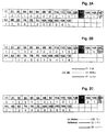
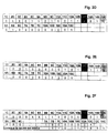
- a second positive input B of the second comparator (2) is connected to the output C of the voltage frequency converter circuit (8). How the circuit of the control logic assembly will now be described in link with the table of states and figures 2A to 2F.
- the operation of the device will be explained below.
- the goal of the system is to have a constant speed of rotation of the compressor (34) as long as the set temperature has not been reached and whatever or the engine rotation speed.
- the hydraulic pump and the control will make sure that we get to the compressor this constant speed which is for example 1500 rpm.
- the time required for the temperature is always longer than the system reaction time servo motor.
- the system works with two speed references, one (Z1) corresponding to the nominal speed of the compressor and the other (Z2) at a slightly lower speed, defined respectively by two zener diodes (151, 152).
- the pump turntable positions can also be modified by the signals of the comparators (1, 2) determining the direction rotation or stop of the servomotor, depending on the speed variation of the heat engine or propulsion engine.
- the switch (26) is used to switching the air conditioning on and off.
- the switch (24) indicates to the control system, when closed, that the displacement of the pump is zero, that is to say that the plate is in the neutral position. The basically will depend on six different situations represented by the various state tables of FIGS. 2A to 2F.
- the signal on the input (2B) is then higher than the signal on the input (2A) of the comparator (2) and the output (2C) is at logic level 1.
- the signals on the comparator inputs (1) are identical to the previous case as well as those on the comparator (3) since the set temperature is not yet reached.
- This situation at the comparator inputs generates the signals logic represented by the state table of figure (2B) in which we can see that the output (12C) and the output (14C) are both at level 1. This has the effect of stopping the rotation of the servo motor (45) and the pump plate (31) remains in the position it was in.
- We observe that in this state table the output of the door (13C) has passed from the logic state 1 in logic state 0 which causes the servo motor to stop by passing outputs (12C) and (14C) to 1.
- the determining values will be those fixed at the input (90A) of the inverter (90) which sets the output (90C) to the value 0 and the output (6C) to 0 and to the input (9B) of the door (9) which will fix the output (9C) to the value 1 imposing a direction of rotation with the servomotor corresponding to a reduction in displacement of the pump.
- the door (7) will have an input (7A) at logic level 1 and its output will only go to 1 when the entry (7B) has reached level 1. This is will occur when the switch (24) is closed, i.e. when the tray will reach the neutral position. During all the rest of the time the exit (7C) and the input (10A) being at zero, the output (10C) will remain at zero. The plateau therefore goes be brought to the neutral position before the system stops which places the system in good condition for restarting a cycle of cooling.
- the group hermetic type refrigeration machine driven by a hydraulic motor specific displacement which is itself actuated by a hydraulic pump variable displacement provides a better coefficient of performance because a hermetic compressor eliminates the sealing conditions of garnish.
- a hermetic group has a duration of longer than the life of the vehicle and does not require recharging in refrigeration gas.
- the constant rotation speed of the compressor allows to obtain a better yield which becomes independent of the speed of rotation of the heat engine or propulsion engine.
- the pump variable displacement hydraulic does the necessary to adapt the speed of constant rotation of the compressor. The device avoids any change brutal torque because when the set temperature is reached the compressor will see its speed decrease.
- thermodynamic cycle there will be no more need to start the complete thermodynamic cycle again, avoiding lose this thermodynamic irreversibility, no consumption additional electric because no more electromagnetic clutch.
- the choice of where the compressor is installed is not limited because of pipes between the hydraulic motor and the pump allow to move away the compressor for high heat sources.
Landscapes
- Physics & Mathematics (AREA)
- Thermal Sciences (AREA)
- Engineering & Computer Science (AREA)
- Mechanical Engineering (AREA)
- Control Of Positive-Displacement Pumps (AREA)
- Air-Conditioning For Vehicles (AREA)
- Auxiliary Drives, Propulsion Controls, And Safety Devices (AREA)
Claims (6)
- System zur Steuerung einer Fahrzeugklimaanlage mit hermetischem Kompressor,
dadurch gekennzeichnet, dass das Steuersystem ein System zur Regulierung der Drehzahl des hermetischen Kompressors (34) aufweist, derart, dass der Kompressor, der durch eine Verstellpumpeneinheit bzw. Pumpeneinheit (30) mit variablem Zylinderinhalt angetrieben wird, die an einen Hydrokonstantmotor (33) bzw. Hydromotor mit konstantem Hubraum gekoppelt ist, sich bei einer Drehzahl dreht, die so nahe wie möglich der Nenndrehzahl des Kompressors ist, unabhängig von der Drehzahl des Verbrennungsmotors oder des Antriebsmotors, und eine Messfühlereinrichtung (8) gestattet, die Drehzahl der Welle des Hydromotors (33) zu messen, der mit dem Kompressor (34) derart verbunden ist, dass durch den Komparator (1) die Richtung der Verlagerung der Scheibe (31) der Pumpe (30) variablen Zylinderinhalts als Funktion der Drehzahländerungen des Hydromotors bezogen auf eine Solldrehzahl variiert. - Klimaanlagesystem nach Anspruch 1,
dadurch gekennzeichnet, dass die Änderung des Zylinderinhalts der Pumpe (30) erfolgt, indem das Gefälle einer Pumpe (31) mit Scheibe durch eine Servomotoreinheit (45) modifiziert wird, der durch eine elektronische Logik gesteuert wird. - Klimaanlagesystem nach Anspruch 1 oder 2,
dadurch gekennzeichnet, dass ein Endschalter (24) der Scheibe, der die neutrale Position der Scheibe anzeigt, das Anhalten des Servomotors (45) bestimmt. - Klimaanlagesystem nach einem der vorhergehenden Ansprüche,
dadurch gekennzeichnet, dass ein Regulierungssystem den Zylinderinhalt der Pumpe als Funktion einer Solltemperatur (19) und der Temperatur variiert, die im Karrosseriegehäuse durch einen Messfühler (4) gemessen wird. - Klimaanlagesystem nach einem der vorhergehenden Ansprüche,
dadurch gekennzeichnet, dass ein weiterer Komparator (32) gestattet, zwei verschiedene Solldrehzahlen zu bestimmen, eine erste (Z2) nahe der Nenndrehzahl des Kompressors und geringer als diese, wenn die Solltemperatur erreicht wurde, wobei der Servomotor den Zylinderinhalt der Pumpe in umgekehrter Richtung von der Änderungsrichtung der Pumpengeschwindigkeit variiert, und eine zweite (Z1), die der Nenndrehzahl entspricht. - Klimaanlagesystem nach Anspruch 5,
dadurch gekennzeichnet, dass ein dritter Komparator (2) gestattet, für jede Solldrehzahl (Z1 oder Z2) einen Bereich (ε) zu bestimmen, in welchem der Servomotor abgestoppt ist, wobei der Zylinderinhalt der Pumpe nicht mehr variiert.
Applications Claiming Priority (3)
| Application Number | Priority Date | Filing Date | Title |
|---|---|---|---|
| FR9601644A FR2744675A1 (fr) | 1996-02-09 | 1996-02-09 | Systeme de commande d'air conditionne pour vehicule automobile |
| FR9601644 | 1996-02-09 | ||
| PCT/FR1997/000252 WO1997028976A1 (fr) | 1996-02-09 | 1997-02-07 | Systeme de commande d'air conditionne pour vehicule automobile |
Publications (2)
| Publication Number | Publication Date |
|---|---|
| EP0832001A1 EP0832001A1 (de) | 1998-04-01 |
| EP0832001B1 true EP0832001B1 (de) | 2000-10-18 |
Family
ID=9489051
Family Applications (1)
| Application Number | Title | Priority Date | Filing Date |
|---|---|---|---|
| EP97903428A Expired - Lifetime EP0832001B1 (de) | 1996-02-09 | 1997-02-07 | Steuerungssystem für eine fahrzeugklimaanlage |
Country Status (9)
| Country | Link |
|---|---|
| US (1) | US5904050A (de) |
| EP (1) | EP0832001B1 (de) |
| JP (1) | JP3992293B2 (de) |
| AT (1) | ATE197021T1 (de) |
| CA (1) | CA2218409C (de) |
| DE (1) | DE69703333T2 (de) |
| ES (1) | ES2151715T3 (de) |
| FR (1) | FR2744675A1 (de) |
| WO (1) | WO1997028976A1 (de) |
Families Citing this family (3)
| Publication number | Priority date | Publication date | Assignee | Title |
|---|---|---|---|---|
| NL2001192C1 (nl) * | 2008-01-17 | 2008-12-09 | Eeuwe Durk Kooi | Voertuig omvattende een luchtconditioneringssysteem. |
| CA2978930A1 (en) * | 2016-09-09 | 2018-03-09 | Terex Usa, Llc | System and method for idle mitigation on a utility truck with an electrically isolated hydraulically controlled aerial work platform |
| JP6981316B2 (ja) * | 2018-03-14 | 2021-12-15 | 株式会社豊田自動織機 | 車載用電動圧縮機 |
Family Cites Families (5)
| Publication number | Priority date | Publication date | Assignee | Title |
|---|---|---|---|---|
| US2101495A (en) * | 1935-10-23 | 1937-12-07 | Oilgear Co | Hydraulic transmission |
| JPH0717151B2 (ja) * | 1987-07-04 | 1995-03-01 | 株式会社豊田自動織機製作所 | 可変容量コンプレッサの運転制御方法 |
| DE3742569A1 (de) * | 1987-12-16 | 1989-07-06 | Klemm Gerhard Maschfab | Hydromechanische antriebsuebertragungsvorrichtung, wie kupplung, getriebe oder dgl. |
| US4976589A (en) * | 1988-04-22 | 1990-12-11 | Honda Giken Kogyo K.K. (Honda Motor Co., Ltd.) | Output control system for an I.C. engine responsive to compressor torque and engine speed |
| JPH061136A (ja) * | 1992-06-19 | 1994-01-11 | Toyota Autom Loom Works Ltd | 車両用空調装置 |
-
1996
- 1996-02-09 FR FR9601644A patent/FR2744675A1/fr active Pending
-
1997
- 1997-02-07 WO PCT/FR1997/000252 patent/WO1997028976A1/fr not_active Ceased
- 1997-02-07 JP JP52823597A patent/JP3992293B2/ja not_active Expired - Lifetime
- 1997-02-07 CA CA002218409A patent/CA2218409C/fr not_active Expired - Lifetime
- 1997-02-07 ES ES97903428T patent/ES2151715T3/es not_active Expired - Lifetime
- 1997-02-07 AT AT97903428T patent/ATE197021T1/de not_active IP Right Cessation
- 1997-02-07 EP EP97903428A patent/EP0832001B1/de not_active Expired - Lifetime
- 1997-02-07 DE DE69703333T patent/DE69703333T2/de not_active Expired - Lifetime
- 1997-02-07 US US08/930,760 patent/US5904050A/en not_active Expired - Lifetime
Also Published As
| Publication number | Publication date |
|---|---|
| DE69703333T2 (de) | 2001-05-23 |
| JP3992293B2 (ja) | 2007-10-17 |
| ATE197021T1 (de) | 2000-11-15 |
| WO1997028976A1 (fr) | 1997-08-14 |
| JPH11503510A (ja) | 1999-03-26 |
| CA2218409C (fr) | 2003-04-01 |
| CA2218409A1 (fr) | 1997-08-14 |
| FR2744675A1 (fr) | 1997-08-14 |
| ES2151715T3 (es) | 2001-01-01 |
| EP0832001A1 (de) | 1998-04-01 |
| US5904050A (en) | 1999-05-18 |
| DE69703333D1 (de) | 2000-11-23 |
Similar Documents
| Publication | Publication Date | Title |
|---|---|---|
| CN101946087B (zh) | 用于控制内燃机的起动器的方法及其应用 | |
| EP3870818B1 (de) | Verfahren zum kühlen eines ausrüstungsteils eines fahrzeugs und fahrzeug mit dieser ausrüstung | |
| EP0715979B1 (de) | Klimavorrichtung für ein abgestelltes und fahrendes Fahrzeug | |
| US7849840B2 (en) | Electric motor assisted mechanical supercharging system | |
| FR2984236A1 (fr) | Systeme de commande de compresseur destine a un conditionneur d'air de vehicule | |
| FR2839119A1 (fr) | Systeme de demarrage de moteur | |
| EP1072766B1 (de) | Kühlungssteuervorrichtung einer Brennkraftmaschine eines Kraftfahrzeugs | |
| CA2218409C (fr) | Systeme de commande d'air conditionne pour vehicule automobile | |
| FR2802151A1 (fr) | Systeme de conditionnement d'air pour vehicules | |
| JPH10159577A (ja) | 電動機駆動過給機の制御装置 | |
| FR2808304A1 (fr) | Dispositif de refroidissement a l'arret d'un moteur thermique de vehicule automobile | |
| FR2821121A1 (fr) | Procede et dispositif de commande d'un compresseur a entrainement mecanique d'un moteur a combustion interne | |
| FR2781197A1 (fr) | Mode de fonctionnement d'une installation de climatisation d'une cabine ou cockpit d'helicoptere | |
| FR2481424A1 (fr) | Systeme de reglage automatique de la vitesse du ventilateur d'un conditionneur d'air | |
| FR2743761A1 (fr) | Dispositif de commande de climatiseur de vehicules automobiles | |
| FR3123255A1 (fr) | Vehicule comprenant un dispositif de chauffage de l’habitacle | |
| WO2015063414A1 (fr) | Procédé et système de génération de puissance auxiliaire dans un aéronef | |
| FR2840961A1 (fr) | Procede et dispositif pour empecher un etat de calage dans un systeme de moteur a combustion interne equipe d'un ensemble a demarreur-alternateur | |
| WO2022064053A1 (fr) | Procédé de contrôle d'un compresseur a cylindrée fixe pour système de refroidissement d'un véhicule automobile a combustion | |
| FR3061744B1 (fr) | Systeme de gestion d'air d'admission pour un moteur thermique de vehicule automobile | |
| EP1924459A1 (de) | System zum antrieb von mit einer wärmekraftmaschine verbundenen elektrischen geräten | |
| FR2704906A1 (fr) | Système de commande d'un dispositif pour le refroidissement d'un moteur à combustion interne. | |
| FR2800529A1 (fr) | Moteur pour le deplacement d'un volet d'une installation de ventilation, chauffage et/ou climatisation d'un vehicule automobile, a commande perfectionnee | |
| JP2001329866A (ja) | スロットルシャフトの駆動装置 | |
| EP4719793A1 (de) | Wärmekonditionierungssystem |
Legal Events
| Date | Code | Title | Description |
|---|---|---|---|
| PUAI | Public reference made under article 153(3) epc to a published international application that has entered the european phase |
Free format text: ORIGINAL CODE: 0009012 |
|
| 17P | Request for examination filed |
Effective date: 19980121 |
|
| AK | Designated contracting states |
Kind code of ref document: A1 Designated state(s): AT BE CH DE DK ES FI FR GB GR IE IT LI LU MC NL PT SE |
|
| RAP1 | Party data changed (applicant data changed or rights of an application transferred) |
Owner name: TOUCHTUNES MUSIC CORPORATION |
|
| GRAG | Despatch of communication of intention to grant |
Free format text: ORIGINAL CODE: EPIDOS AGRA |
|
| 17Q | First examination report despatched |
Effective date: 19990802 |
|
| GRAG | Despatch of communication of intention to grant |
Free format text: ORIGINAL CODE: EPIDOS AGRA |
|
| GRAH | Despatch of communication of intention to grant a patent |
Free format text: ORIGINAL CODE: EPIDOS IGRA |
|
| GRAH | Despatch of communication of intention to grant a patent |
Free format text: ORIGINAL CODE: EPIDOS IGRA |
|
| GRAA | (expected) grant |
Free format text: ORIGINAL CODE: 0009210 |
|
| AK | Designated contracting states |
Kind code of ref document: B1 Designated state(s): AT BE CH DE DK ES FI FR GB GR IE IT LI LU MC NL PT SE |
|
| PG25 | Lapsed in a contracting state [announced via postgrant information from national office to epo] |
Ref country code: NL Free format text: LAPSE BECAUSE OF FAILURE TO SUBMIT A TRANSLATION OF THE DESCRIPTION OR TO PAY THE FEE WITHIN THE PRESCRIBED TIME-LIMIT Effective date: 20001018 Ref country code: IE Free format text: LAPSE BECAUSE OF NON-PAYMENT OF DUE FEES Effective date: 20001018 Ref country code: FI Free format text: LAPSE BECAUSE OF FAILURE TO SUBMIT A TRANSLATION OF THE DESCRIPTION OR TO PAY THE FEE WITHIN THE PRESCRIBED TIME-LIMIT Effective date: 20001018 Ref country code: AT Free format text: LAPSE BECAUSE OF FAILURE TO SUBMIT A TRANSLATION OF THE DESCRIPTION OR TO PAY THE FEE WITHIN THE PRESCRIBED TIME-LIMIT Effective date: 20001018 |
|
| REF | Corresponds to: |
Ref document number: 197021 Country of ref document: AT Date of ref document: 20001115 Kind code of ref document: T |
|
| REG | Reference to a national code |
Ref country code: CH Ref legal event code: EP |
|
| REG | Reference to a national code |
Ref country code: IE Ref legal event code: FG4D Free format text: FRENCH |
|
| REF | Corresponds to: |
Ref document number: 69703333 Country of ref document: DE Date of ref document: 20001123 |
|
| ITF | It: translation for a ep patent filed | ||
| GBT | Gb: translation of ep patent filed (gb section 77(6)(a)/1977) |
Effective date: 20001206 |
|
| REG | Reference to a national code |
Ref country code: ES Ref legal event code: FG2A Ref document number: 2151715 Country of ref document: ES Kind code of ref document: T3 |
|
| PG25 | Lapsed in a contracting state [announced via postgrant information from national office to epo] |
Ref country code: SE Free format text: LAPSE BECAUSE OF FAILURE TO SUBMIT A TRANSLATION OF THE DESCRIPTION OR TO PAY THE FEE WITHIN THE PRESCRIBED TIME-LIMIT Effective date: 20010118 Ref country code: PT Free format text: LAPSE BECAUSE OF FAILURE TO SUBMIT A TRANSLATION OF THE DESCRIPTION OR TO PAY THE FEE WITHIN THE PRESCRIBED TIME-LIMIT Effective date: 20010118 Ref country code: DK Free format text: LAPSE BECAUSE OF FAILURE TO SUBMIT A TRANSLATION OF THE DESCRIPTION OR TO PAY THE FEE WITHIN THE PRESCRIBED TIME-LIMIT Effective date: 20010118 |
|
| PG25 | Lapsed in a contracting state [announced via postgrant information from national office to epo] |
Ref country code: GR Free format text: LAPSE BECAUSE OF FAILURE TO SUBMIT A TRANSLATION OF THE DESCRIPTION OR TO PAY THE FEE WITHIN THE PRESCRIBED TIME-LIMIT Effective date: 20010119 |
|
| PG25 | Lapsed in a contracting state [announced via postgrant information from national office to epo] |
Ref country code: MC Free format text: LAPSE BECAUSE OF NON-PAYMENT OF DUE FEES Effective date: 20010228 |
|
| NLV1 | Nl: lapsed or annulled due to failure to fulfill the requirements of art. 29p and 29m of the patents act | ||
| PLBE | No opposition filed within time limit |
Free format text: ORIGINAL CODE: 0009261 |
|
| STAA | Information on the status of an ep patent application or granted ep patent |
Free format text: STATUS: NO OPPOSITION FILED WITHIN TIME LIMIT |
|
| REG | Reference to a national code |
Ref country code: IE Ref legal event code: FD4D |
|
| 26N | No opposition filed | ||
| REG | Reference to a national code |
Ref country code: GB Ref legal event code: IF02 |
|
| REG | Reference to a national code |
Ref country code: CH Ref legal event code: PL |
|
| REG | Reference to a national code |
Ref country code: CH Ref legal event code: AEN Free format text: LE BREVET A ETE REACTIVE SELON LA DEMANDE DE POURSUITE DE LA PROCEDURE DU 03.11.2003. |
|
| PGFP | Annual fee paid to national office [announced via postgrant information from national office to epo] |
Ref country code: GB Payment date: 20040212 Year of fee payment: 8 |
|
| PGFP | Annual fee paid to national office [announced via postgrant information from national office to epo] |
Ref country code: CH Payment date: 20040224 Year of fee payment: 8 |
|
| PG25 | Lapsed in a contracting state [announced via postgrant information from national office to epo] |
Ref country code: IT Free format text: LAPSE BECAUSE OF NON-PAYMENT OF DUE FEES Effective date: 20050207 Ref country code: GB Free format text: LAPSE BECAUSE OF NON-PAYMENT OF DUE FEES Effective date: 20050207 |
|
| PG25 | Lapsed in a contracting state [announced via postgrant information from national office to epo] |
Ref country code: LI Free format text: LAPSE BECAUSE OF NON-PAYMENT OF DUE FEES Effective date: 20050228 Ref country code: CH Free format text: LAPSE BECAUSE OF NON-PAYMENT OF DUE FEES Effective date: 20050228 |
|
| PGFP | Annual fee paid to national office [announced via postgrant information from national office to epo] |
Ref country code: LU Payment date: 20050718 Year of fee payment: 9 |
|
| PGFP | Annual fee paid to national office [announced via postgrant information from national office to epo] |
Ref country code: BE Payment date: 20050914 Year of fee payment: 9 |
|
| GBPC | Gb: european patent ceased through non-payment of renewal fee |
Effective date: 20050207 |
|
| REG | Reference to a national code |
Ref country code: CH Ref legal event code: PL |
|
| PG25 | Lapsed in a contracting state [announced via postgrant information from national office to epo] |
Ref country code: LU Free format text: LAPSE BECAUSE OF NON-PAYMENT OF DUE FEES Effective date: 20060228 Ref country code: BE Free format text: LAPSE BECAUSE OF NON-PAYMENT OF DUE FEES Effective date: 20060228 |
|
| BERE | Be: lapsed |
Owner name: *TOUCHTUNES MUSIC CORP. Effective date: 20060228 |
|
| REG | Reference to a national code |
Ref country code: FR Ref legal event code: GC |
|
| REG | Reference to a national code |
Ref country code: FR Ref legal event code: PLFP Year of fee payment: 20 |
|
| PGFP | Annual fee paid to national office [announced via postgrant information from national office to epo] |
Ref country code: DE Payment date: 20160302 Year of fee payment: 20 Ref country code: ES Payment date: 20160217 Year of fee payment: 20 |
|
| PGFP | Annual fee paid to national office [announced via postgrant information from national office to epo] |
Ref country code: FR Payment date: 20160125 Year of fee payment: 20 |
|
| REG | Reference to a national code |
Ref country code: DE Ref legal event code: R071 Ref document number: 69703333 Country of ref document: DE |
|
| REG | Reference to a national code |
Ref country code: ES Ref legal event code: FD2A Effective date: 20170526 |
|
| PG25 | Lapsed in a contracting state [announced via postgrant information from national office to epo] |
Ref country code: ES Free format text: LAPSE BECAUSE OF EXPIRATION OF PROTECTION Effective date: 20170208 |