EP0831988B1 - Procede permettant la realisation d'une extrusion par etirage par injection de resine en utilisant plusieurs resines - Google Patents
Procede permettant la realisation d'une extrusion par etirage par injection de resine en utilisant plusieurs resines Download PDFInfo
- Publication number
- EP0831988B1 EP0831988B1 EP96917007A EP96917007A EP0831988B1 EP 0831988 B1 EP0831988 B1 EP 0831988B1 EP 96917007 A EP96917007 A EP 96917007A EP 96917007 A EP96917007 A EP 96917007A EP 0831988 B1 EP0831988 B1 EP 0831988B1
- Authority
- EP
- European Patent Office
- Prior art keywords
- die
- interior
- resin material
- impregnated
- layers
- Prior art date
- Legal status (The legal status is an assumption and is not a legal conclusion. Google has not performed a legal analysis and makes no representation as to the accuracy of the status listed.)
- Expired - Lifetime
Links
Images


Classifications
-
- B—PERFORMING OPERATIONS; TRANSPORTING
- B29—WORKING OF PLASTICS; WORKING OF SUBSTANCES IN A PLASTIC STATE IN GENERAL
- B29C—SHAPING OR JOINING OF PLASTICS; SHAPING OF MATERIAL IN A PLASTIC STATE, NOT OTHERWISE PROVIDED FOR; AFTER-TREATMENT OF THE SHAPED PRODUCTS, e.g. REPAIRING
- B29C70/00—Shaping composites, i.e. plastics material comprising reinforcements, fillers or preformed parts, e.g. inserts
- B29C70/04—Shaping composites, i.e. plastics material comprising reinforcements, fillers or preformed parts, e.g. inserts comprising reinforcements only, e.g. self-reinforcing plastics
- B29C70/28—Shaping operations therefor
- B29C70/40—Shaping or impregnating by compression not applied
- B29C70/50—Shaping or impregnating by compression not applied for producing articles of indefinite length, e.g. prepregs, sheet moulding compounds [SMC] or cross moulding compounds [XMC]
- B29C70/52—Pultrusion, i.e. forming and compressing by continuously pulling through a die
- B29C70/521—Pultrusion, i.e. forming and compressing by continuously pulling through a die and impregnating the reinforcement before the die
-
- B—PERFORMING OPERATIONS; TRANSPORTING
- B29—WORKING OF PLASTICS; WORKING OF SUBSTANCES IN A PLASTIC STATE IN GENERAL
- B29C—SHAPING OR JOINING OF PLASTICS; SHAPING OF MATERIAL IN A PLASTIC STATE, NOT OTHERWISE PROVIDED FOR; AFTER-TREATMENT OF THE SHAPED PRODUCTS, e.g. REPAIRING
- B29C70/00—Shaping composites, i.e. plastics material comprising reinforcements, fillers or preformed parts, e.g. inserts
- B29C70/003—Shaping composites, i.e. plastics material comprising reinforcements, fillers or preformed parts, e.g. inserts characterised by the matrix material, e.g. material composition or physical properties
- B29C70/0035—Shaping composites, i.e. plastics material comprising reinforcements, fillers or preformed parts, e.g. inserts characterised by the matrix material, e.g. material composition or physical properties comprising two or more matrix materials
-
- B—PERFORMING OPERATIONS; TRANSPORTING
- B29—WORKING OF PLASTICS; WORKING OF SUBSTANCES IN A PLASTIC STATE IN GENERAL
- B29C—SHAPING OR JOINING OF PLASTICS; SHAPING OF MATERIAL IN A PLASTIC STATE, NOT OTHERWISE PROVIDED FOR; AFTER-TREATMENT OF THE SHAPED PRODUCTS, e.g. REPAIRING
- B29C70/00—Shaping composites, i.e. plastics material comprising reinforcements, fillers or preformed parts, e.g. inserts
- B29C70/04—Shaping composites, i.e. plastics material comprising reinforcements, fillers or preformed parts, e.g. inserts comprising reinforcements only, e.g. self-reinforcing plastics
- B29C70/28—Shaping operations therefor
- B29C70/40—Shaping or impregnating by compression not applied
- B29C70/50—Shaping or impregnating by compression not applied for producing articles of indefinite length, e.g. prepregs, sheet moulding compounds [SMC] or cross moulding compounds [XMC]
- B29C70/52—Pultrusion, i.e. forming and compressing by continuously pulling through a die
- B29C70/523—Pultrusion, i.e. forming and compressing by continuously pulling through a die and impregnating the reinforcement in the die
Definitions
- the present invention relates in general to resin injected pultrusion and, more particularly, to a method for performing resin injected pultrusion employing multiple resins.
- Pultrusion of resin-impregnated fibers is well known.
- pultrusion of resin-impregnated fibers involves impregnating a multitude of continuous fibers and/or continuous fiber/mat combinations with a suitable resin material and passing the impregnated fibers through a die.
- the continuous fibers were impregnated by passing the fibers through a bath of liquid resin material, thereby completely wetting or coating the fibers in the resin material.
- the coated fibers were then consolidated and passed through a pultrusion or cure die where the fibers were formed into a desired shaped and the resin material cured to fix the fibers in place.
- resin materials for the most part, comprise blends of organic compounds, a significant portion of which are volatile organic compounds or VOCs.
- VOCs volatile organic compounds
- the emission of VOCs is strictly monitored and limited by the various governmental agencies and regulations. Compliance with the regulations can become quite expensive.
- Resin baths, as employed in the prior-art impregnation processes, are open or partially open to the atmosphere and involve the use of large quantities of resin materials. The level of VOC emissions in these prior-art processes is much larger than desired.
- EP-A-0233171 describes a procedure in which a plurality of fiber strands are continuously impregnated with a Duroplast hardening resin, preferably polyester, the strands are combined into one bundle which is axially inserted in an elongated run-through mold whose inside is shaped accordingly to the shape of the profile shape to be produced, and the resin is hardened in the run-through mold.
- a resin material to constitute the outer surface of the final profile may be injected into the run-through mold, all of the individual fiber strands which are combined to form the bundle are themselves already impregnated with resin before entering the run-through mold.
- prior-art pultrusion processes have impregnated reinforcement packs with a single resin material. It would be desirable, however, to selectively impregnate one or more first reinforcement pack layers with a first resin, combine those impregnated first layers with second layers, and impregnate the reinforcement pack with a second resin material.
- a pultruded part may be formed having first layers with performance properties that differ from those of second layers of the pultruded part. Accordingly, the overall performance of a pultruded part may be more specifically tailored for its particular intended use.
- the exterior second layer may comprise at least two exterior second layers, and the interior first layer may comprise supplying two interior first layers.
- both the interior first and exterior second layers comprises layers of continuous filament mats, rovings, or veils.
- Each interior first layer may comprise an interior pack layer, and each exterior second layer may comprise an exterior pack layer.
- the step of impregnating the interior first layer preferably comprises the step of passing the interior first layer into an impregnation die and injecting the first strength-imparting resin material into the impregnation die.
- the step of impregnating the interior first layer may further comprise the step of impregnating the interior first layer with a second resin material prior to passing the pack into the injection die.
- all of the first, second, and final resin materials are substantially nonidentical.
- the step of impregnating the interior first layer comprises the steps of impregnating one interior first layer with a first strength-imparting resin material and another interior first layer with a second resin material.
- the step of passing the reinforcement pack into the injection die suitably comprises the steps of shaping and compressing the reinforcement pack before it is passed into the injection die.
- the method may further comprise the step of passing the impregnated pultrusion reinforcement pack to a curing die to cure the resin materials.
- the curing die is sealingly coupled to the injection die, and the impregnated reinforcement pack is maintained under compression as it is passed to the curing die.
- FIG. 1 shows schematically resin injected pultrusion apparatus 10 for forming a pultruded product 100.
- the apparatus 10 includes spools 12a and 12b having ' continuous reinforcement material 14 provided thereon, an impregnation die 16, a highpressure injection die 18, and a curing die 20.
- the continuous reinforcement material 14 comprises glass or polymer fibers, rovings or bundles of fibers, continuous filaments mats, fiber or polymer cloths, or veil.
- Spools 12a supply reinforcement material 14 to be used as interior layers 22 in a reinforcement pack 36
- spools 12b supply reinforcement material 14 to be used as exterior layers 24 in the reinforcement pack 36. While only four spools 12a and 12b are illustrated, more or less may be provided as desired.
- Interior layers 22 pass separately from the exterior layers 24 through an impregnation die 16.
- the interior layers 22 are impregnated with at least a first resin material in the die 16.
- Impregnation dies are well known in the art. One such die suitable in the present invention is disclosed in U.S. Patent 4,681,722.
- Impregnation die 16 includes a passageway 26 extending completely therethrough.
- Resin supply apparatus 28 communicates with the die 16 and supplies at least a first resin material under substantially constant pressure to the passageway 26.
- Supply apparatus 28 in the illustrated embodiment, includes supply devices 30a and 30b and supply lines 32a and 32b.
- Supply devices 30a and 30b may include any number of conventional constant-pressure pumps such as a double-action piston pump, a constant-pressure pot, or a multicomponent mixing chamber for in-line mixing of at least one uncatalyzed component and at least one catalyzed component of a multicomponent resin material just prior to injection into the impregnation die 16.
- Supply apparatus 28 further includes conventional heaters 34a and 34b which serve to heat the resin material to lower its viscosity prior to it being injected into the impregnation die 16. As shown in Figure 1, heaters 34a and 34b are located between supply devices 30a and 30b and the impregnation die 16.
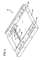
- the impregnation die 16 comprises a first die body 102 and a second die body 104, both of which may be formed from a metal or other appropriate material.
- the first die body 102 has two inner recesses 110 which are positioned opposite to two inner recesses 120 provided in the second die body 104.
- the inner recesses 110 and 120 define shim rail receiving channels 112. Shim rails (not shown) are placed in the receiving channels 112 and define the width and thickness of the passageway 26.
- the first die body 102 and the second die body 104 are coupled to one another.
- a plurality of apertures 122 extend through the first die body 102, and a plurality of apertures 124 extend through the second die body 104.
- the shim rails are provided with openings that are spaced and sized to correspond with apertures 122 and 124.
- Bolts 126 pass through the apertures 122 in the first die body 102, through the openings in the shim rails, and threadedly engage the apertures 124 in the second die body 104.
- Interior layers 22 pass into impregnation die 16 through an entry portion 128 of the inner passageway 26.
- the passageway 26, in the illustrated embodiment, is not tapered and is sized to correspond to the dimensions of the interior layers 22 when not compressed.
- a tapered passageway and compression of the interior layers 22 may be provided if desired.
- the interior layers 22 traveling through the passageway 26 pass by a weir 132. Resin material is injected into the weir 132 to impregnate the interior layers 22.
- the weir 132 comprises a channel or recess 134 formed, in the illustrated embodiment, in the second die body 104. Alternatively, the weir 132 may be formed in the first die body 102 or in both of the first and second die bodies 102 and 104.
- Channel 134 is positioned substantially perpendicular to the direction of travel of the interior layers 22 through the passageway 26.
- the channel 134 has a depth D equal to about 13 mm (1 ⁇ 2 inch), a width of W equal to about 13 mm (1 ⁇ 2 inch), and a length L which will vary depending upon the width of the interior layers 22.
- Resin material is injected into the weir 132 through injection ports 136 which communicate with the resin supply apparatus 28.
- the injection pressure of the resin material ranges from about 34 kPa to 103 kPa (5 to 15 pounds per square inch (psi)).
- psi pounds per square inch
- the injection pressure will vary depending upon the thickness and density of the interior layers 22, as well as the viscosity of the chosen resin material.
- the interior layers 22 are combined with the exterior layers 24 to form the reinforcement pack 36.
- a conventional shaping die 38 is provided for combining the interior layers 22 and exterior layers 24 to form the reinforcement pack 36.
- shaping die 38 properly aligns the layers relative to one another, and compresses the layers 22 and 24 to an appropriate thickness.
- the injection die 18 may comprise an injection die such as disclosed in U.S. Patent No. 5,073,413 to Koppernacs et al. or U.S. Patent No. 3,556,888 to Goldsworthy. However, particularly preferred is the injection die disclosed in U.S. Patent No. 5,747,075 entitled “Methods and Apparatus For Resin Impregnated Pultrusion,” filed June 7,1995, by Gauchel et al. and assigned to the same assignee as the present invention
- Injection die 18 generally comprises an entry portion 40, an internal passageway 42, and an exit portion 44.
- Reinforcement pack 36 enters the die 18 through the entry portion 40.
- Conventional pulling means (not shown) is provided downstream from the curing die 20 for pulling the reinforcement materials from the spools 12a and 12b and through the dies 16, 38, 18, and 20. As the reinforcement pack 36 is pulled through the passageway 42, the pack 36 is compressed and impregnated with a final resin material.
- Injection die 18 includes resin supply apparatus 46 for supplying the final resin material to the injection die 18.
- Supply apparatus 46 comprises supply lines 48a and 48b, supply devices 50a and 50b, and heaters 52a and 52b.
- the supply devices 50a and 50b may comprise any of the devices discussed above that may be used as supply devices 30a and 30b.
- Final resin material may be either a single resin composition injected into the die 18 through one or more injection ports (not shown) or may comprise different multiple resin materials injected into different injection ports (not shown) in the injection die 18.
- Injection die 18 is preferably sealingly coupled or integrally formed with the curing die 20.
- the reinforcement pack 36 leaves the injection die 18 through the exit portion 44, it directly enters the curing die 20 without being exposed to the surrounding environment. Further, the pack 36 is constantly maintained under pressure as it moves from the injection die 18 into the curing die 20.
- Curing die 20 includes an entry 54, a central passage 56, and an exit 58.
- Curing die 20 may comprise a curing die such as described in the above-referenced U.S. patent entitled “Methods and Apparatus For Resin Impregnated Pultrusion”.
- the curing die 20 acts to shape pack 36 to its final intended shape and to cure the resin materials to form the final pultruded product 100.
- first resin material is injected into the impregnation die 16 while a final resin material is injected into the injection die 18.
- the first resin material and the final resin material are substantially nonidentical or different resin materials.
- the first and final resin materials are not identical or the same. Indeed, by employing nonidentical resin materials, different properties may be imparted to the interior layers 22 and the exterior layers 24.
- a pultruded part intended for use as a motor vehicle bumper beam may include interior layers impregnated with a strength-imparting resin, while the outer layers are impregnated with a flexibility imparting resin so that those layers are capable of absorbing high quantities of energy resulting from an impact.
- a pultruded part intended for use as a chemical mixing blade may be impregnated with a final resin material which comprises a chemical-resistance-imparting resin, and the interior layers may be impregnated with a strength-imparting resin.
- the final resin material is applied before the first resin material has had sufficient time to substantially cure.
- a portion of the first resin material migrates into one or more of the exterior layers 24 while a portion of the final resin material migrates into one or more of the interior layers 22.
- This migration of resin materials reduces the likelihood of the formation of voids or zones of little or no resin material at the interface between the exterior layers 24 and the interior layers 22. Voids or zones of little or no resin material tend to weaken the product 100 and decrease its overall performance.
- impregnation of the pack 36 with the final resin material prior to the first resin material fully curing results in frictionior bonding of adjacent or interface interior and exterior layers 22 and 24.
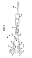
- FIG. 2 there is seen an additional embodiment of the present invention.
- Spools 12 having reinforcement materials 14, as described above, are provided.
- the reinforcement materials 14 pass through a shaping die 38 to form a pack 36, pass into an injection die 18 where a final resin material is injected and, finally, pass through a curing die 20, where the resin material is allowed to cure, all as described above.
- a first interior layer 60 passes through a first impregnation die 64 and a second interior layer 62 passes through a second impregnation die 66.
- the impregnation dies 64 and 66 are substantially the same as the impregnation die 16 discussed above.
- the resin materials injected into the injection dies 64 and 66 may be the same or different.
- the first interior layer 60 may be impregnated with a first resin material
- the second interior layer 62 may be impregnated with a second resin material which differs from the first resin material. At least one or both of the first and second resin materials is substantially nonidentical to the final resin material injected into the injection die 18.
Claims (14)
- Procédé pour réaliser une pultrusion avec injection de résine, comprenant les étapes qui consistent à :caractérisé en ce que la première couche intérieure est imprégnée avec la matière résineuse impartissant une résistance dans une filière d'imprégnation, en ce que le paquet de renforcement est imprégné avec la matière résineuse finale dans une filière d'injection, et en ce que la matière résineuse impartissant une résistance et la matière résineuse finale sont sensiblement différentes.délivrer au moins une première couche intérieure continue (22) et au moins une seconde couche extérieure continue (24);imprégner la première couche intérieure avec au moins une première matière résineuse impartissant une résistance;combiner la première couche intérieure imprégnée et la seconde couche extérieure pour former un paquet de renforcement de pultrusion (36); etimprégner le paquet de renforcement (36) avec la matière résineuse finale pour former un paquet de renforcement de pultrusion imprégné,
- Procédé selon la revendication 1, dans lequel au moins deux secondes couches extérieures (24) sont délivrées.
- Procédé selon la revendication 1 ou la revendication 2, dans lequel au moins deux premières couches intérieures (60, 62) sont délivrées.
- Procédé selon la revendication 3, dans lequel l'étape d'imprégnation comprend l'imprégnation de l'une des premières couches intérieures (60, 62) avec la première matière résineuse impartissant une résistance et l'imprégnation de l'autre première couche intérieure avec une seconde matière résineuse impartissant une résistance.
- Procédé selon l'une quelconque des revendications 1 à 4, dans lequel l'étape d'imprégnation de la première couche intérieure (22) comprend le passage de celle-ci dans une filière d'imprégnation (16) et l'injection de la première matière résineuse impartissant une résistance dans la filière d'imprégnation.
- Procédé selon l'une quelconque des revendications 1 à 5, comprenant également l'étape d'imprégnation de la première couche intérieure imprégnée avec une seconde matière résineuse préalablement au passage du paquet de renforcement dans la filière d'injection (18).
- Procédé selon la revendication 6, dans lequel les première et seconde matières résineuses ainsi que la matière résineuse finale sont toutes sensiblement différentes.
- Procédé selon l'une quelconque des revendications 1 à 7, dans lequel l'étape de passage du paquet de renforcement (36) dans une filière d'injection (18) comprend les étapes de mise en forme et de compression (38) du paquet de renforcement.
- Procédé selon l'une quelconque des revendications 1 à 8, dans lequel les couches sont choisies dans le groupe constitué par des mats à filaments continus, des stratifils et des voiles.
- Procédé selon la revendication 8 ou la revendication 9, dans lequel les première et seconde matières résineuses ainsi que la matière résineuse finale sont sensiblement différentes.
- Procédé selon l'une quelconque des revendications 1 à 10, dans lequel la résine finale est une résine impartissant une flexibilité.
- Procédé selon l'une quelconque des revendications 1 à 10, dans lequel la résine finale est une résine résistante aux produits chimiques.
- Procédé selon l'une quelconque des revendications 1 à 12, comprenant également l'étape de transfert du paquet de renforcement de pultrusion imprégné (36) à une filière de durcissement (20) pour durcir les matières résineuses présentes dans le paquet de renforcement de pultrusion imprégné.
- Procédé selon la revendication 13, dans lequel la filière de durcissement (20) est accouplée de manière étanche avec la filière d'injection (18) et le paquet de renforcement imprégné (36) est maintenu comprimé pendant son transfert à la filière de durcissement.
Applications Claiming Priority (3)
| Application Number | Priority Date | Filing Date | Title |
|---|---|---|---|
| US08/478,131 US5783013A (en) | 1995-06-07 | 1995-06-07 | Method for performing resin injected pultrusion employing multiple resins |
| US478131 | 1995-06-07 | ||
| PCT/US1996/008444 WO1996040489A1 (fr) | 1995-06-07 | 1996-06-03 | Procede permettant la realisation d'une extrusion par etirage par injection de resine en utilisant plusieurs resines |
Publications (2)
| Publication Number | Publication Date |
|---|---|
| EP0831988A1 EP0831988A1 (fr) | 1998-04-01 |
| EP0831988B1 true EP0831988B1 (fr) | 2003-03-19 |
Family
ID=23898657
Family Applications (1)
| Application Number | Title | Priority Date | Filing Date |
|---|---|---|---|
| EP96917007A Expired - Lifetime EP0831988B1 (fr) | 1995-06-07 | 1996-06-03 | Procede permettant la realisation d'une extrusion par etirage par injection de resine en utilisant plusieurs resines |
Country Status (8)
| Country | Link |
|---|---|
| US (1) | US5783013A (fr) |
| EP (1) | EP0831988B1 (fr) |
| JP (1) | JPH11512980A (fr) |
| KR (1) | KR19990022440A (fr) |
| CN (1) | CN1064307C (fr) |
| DE (1) | DE69626817T2 (fr) |
| TW (1) | TW393394B (fr) |
| WO (1) | WO1996040489A1 (fr) |
Families Citing this family (42)
| Publication number | Priority date | Publication date | Assignee | Title |
|---|---|---|---|---|
| US5866051A (en) * | 1997-04-23 | 1999-02-02 | Industrial Technology Research Institute | Method of making continuous glass fiber-reinforced thermoplastic foam sandwich composites |
| US6179945B1 (en) * | 1998-12-30 | 2001-01-30 | Owens Corning Fiberglas Technology, Inc. | Process for filament winding composite workpieces |
| US6395210B1 (en) | 1999-05-12 | 2002-05-28 | A&P Technology, Inc. | Pultrusion method and device for forming composites using pre-consolidated braids |
| US20020123288A1 (en) * | 1999-06-21 | 2002-09-05 | Pella Corporation | Pultruded part with reinforcing mat |
| US6872273B2 (en) * | 1999-06-21 | 2005-03-29 | Pella Corporation | Method of making a pultruded part with a reinforcing mat |
| US20020123287A1 (en) * | 1999-06-21 | 2002-09-05 | Pella Corporation | Reinforcing mat for a pultruded part |
| US6881288B2 (en) * | 1999-06-21 | 2005-04-19 | Pella Corporation | Method of making a reinforcing mat for a pultruded part |
| US9950452B1 (en) | 2002-06-05 | 2018-04-24 | Benjamin V. Booher | Composite friction elements and pultrusion method of making same |
| US6764057B2 (en) * | 2000-10-23 | 2004-07-20 | Kazak Composites, Incorporated | Low cost tooling technique for producing pultrusion dies |
| US7226559B2 (en) * | 2000-12-08 | 2007-06-05 | Toyota Motor Sales, U.S.A., Inc. | Method for molding structures |
| FR2847113B1 (fr) * | 2002-11-13 | 2007-03-16 | Electricite De France | Procede de fabrication d'une structure de chauffage par rayonnement |
| US6893524B2 (en) * | 2003-01-24 | 2005-05-17 | Glastic Corporation | Method and apparatus for manufacturing a reinforcement |
| US7875337B2 (en) * | 2003-01-24 | 2011-01-25 | Glastic Corporation | Fiber and resin composite reinforcement |
| WO2005010082A2 (fr) * | 2003-07-16 | 2005-02-03 | Corlyte Products, Llc | Composites renforces, et systeme et procede d'elaboration |
| CA2495596A1 (fr) | 2005-02-07 | 2006-08-07 | Resin Systems Inc. | Methode de construction d'un poteau modulaire et poteau modulaire |
| US8101107B2 (en) | 2005-11-23 | 2012-01-24 | Milgard Manufacturing Incorporated | Method for producing pultruded components |
| US7875675B2 (en) | 2005-11-23 | 2011-01-25 | Milgard Manufacturing Incorporated | Resin for composite structures |
| US7901762B2 (en) | 2005-11-23 | 2011-03-08 | Milgard Manufacturing Incorporated | Pultruded component |
| US8597016B2 (en) | 2005-11-23 | 2013-12-03 | Milgard Manufacturing Incorporated | System for producing pultruded components |
| CA2641050A1 (fr) * | 2006-02-07 | 2007-08-16 | Resin Systems Inc. | Procede de pultrusion utilisant de multiples resines |
| WO2007090259A1 (fr) * | 2006-02-07 | 2007-08-16 | Resin Systems Inc. | Procédé de pultrusion utilisant de multiples résines |
| US9266289B2 (en) * | 2006-02-21 | 2016-02-23 | Werner Co. | Fiberglass reinforced plastic products having increased weatherability, system and method |
| US8632708B2 (en) * | 2006-02-21 | 2014-01-21 | Werner Co. | Fiberglass reinforced plastic products having increased weatherability, system and method |
| US8357457B2 (en) * | 2008-08-08 | 2013-01-22 | Green David E | Reinforced wood for overcoming interlaminate shear failure |
| JP5792293B2 (ja) | 2010-06-11 | 2015-10-07 | ティコナ・エルエルシー | 中実で線状の形材から形成された構造部材 |
| EP2585279B8 (fr) | 2010-06-22 | 2016-07-27 | Ticona LLC | Préimprégné thermoplastique contenant des fibres longues et continues et procédé pour sa fabrication |
| KR20130112710A (ko) | 2010-06-22 | 2013-10-14 | 티코나 엘엘씨 | 보강된 속이 빈 프로파일 |
| EP2585277A2 (fr) | 2010-06-22 | 2013-05-01 | Ticona LLC | Procédé de fabrication de profilés pultrudés renforcés |
| WO2012016234A1 (fr) | 2010-07-30 | 2012-02-02 | Ocv Intellectual Capital, Llc | Article extrudé par étirage et son procédé de fabrication |
| EP2922690B1 (fr) * | 2012-11-20 | 2017-04-19 | Vestas Wind Systems A/S | Pales pour éoliennes et leur procédé de fabrication |
| CA2911176C (fr) | 2013-05-07 | 2021-08-10 | Neuvokas Corporation | Procede de fabrication d'un materiau composite |
| RU2702548C2 (ru) | 2015-07-02 | 2019-10-08 | Неувокас Корпорейшн | Способ изготовления композитного материала |
| EP3445572A4 (fr) * | 2016-04-20 | 2019-11-20 | FPInnovations | Procédés de production de structures continues composites en sandwich par pultrusion |
| CN106393739A (zh) * | 2016-08-03 | 2017-02-15 | 内蒙古文德茵莱节能门窗有限公司 | 一种玻璃钢型材的加工生产线 |
| US20210122125A1 (en) * | 2017-06-01 | 2021-04-29 | 3M Innovative Properties Company | Polymer composites and methods of making |
| CN209508726U (zh) * | 2017-09-14 | 2019-10-18 | 洛阳双瑞橡塑科技有限公司 | 一种纤维增强合成轨枕 |
| EP3703937B1 (fr) * | 2017-10-31 | 2021-12-08 | Basf Se | Procédé de pultrusion pour former des structures multicouches de matériaux dissemblables à l'aide d'un dispositif de pultrusion à matrices multiples |
| WO2020106766A1 (fr) * | 2018-11-19 | 2020-05-28 | Shape Corp. | Poutre pultrudée dotée d'un élément traceur visant à localiser une position de renfort de fibres |
| KR102168785B1 (ko) * | 2019-01-29 | 2020-10-22 | (주)카본메카 | 복합소재 이중 인발성형장치 |
| WO2021097058A1 (fr) | 2019-11-12 | 2021-05-20 | Neuvokas Corporation | Procédé de fabrication d'un matériau composite |
| CN111216381A (zh) * | 2020-01-19 | 2020-06-02 | 南京聚发新材料有限公司 | 纤维增强双层树脂复合材料、及其挤成型装置和工艺 |
| US20230415430A1 (en) * | 2020-10-30 | 2023-12-28 | China Petroleum & Chemical Corporation | Thermoplastic composite material, preparation method therefor and use thereof |
Family Cites Families (13)
| Publication number | Priority date | Publication date | Assignee | Title |
|---|---|---|---|---|
| US3033729A (en) * | 1957-08-05 | 1962-05-08 | Samuel M Shobert | Method of continuously making glassreinforced plastic tubing |
| BE606062A (fr) * | 1960-01-15 | |||
| US3244784A (en) * | 1960-01-15 | 1966-04-05 | Universal Moulded Fiber Glass | Method for forming fibre reinforced resin articles |
| FR1539577A (fr) * | 1966-10-11 | 1968-09-13 | English Electric Co Ltd | Procédé et appareillage pour la production continue de matière plastique armée de fibres |
| DE1704787A1 (de) * | 1968-02-07 | 1971-07-29 | Herwig Kepka | Verfahren zur kontinuierlichen Herstellung von Profilen aller Art aus faserverstaerkten Kunststoffen und Einrichtungen hierzu |
| US3684622A (en) * | 1970-06-29 | 1972-08-15 | Glastrusions | Pultrusion machine |
| DK131330B (da) * | 1970-07-30 | 1975-06-30 | H F Drostholm | Fremgangsmåde og apparat til fremstilling af fiberarmerede harpiksprofiler. |
| US3895896A (en) * | 1972-11-03 | 1975-07-22 | Pultrusions Corp | Apparatus for pultruding hollow objects |
| US4681722A (en) * | 1985-10-07 | 1987-07-21 | Owens-Corning Fiberglas Corporation | Method of making a lineal structural member |
| AT391514B (de) * | 1986-01-30 | 1990-10-25 | Interprofil Gfk Gmbh | Fensterrahmenprofil und verfahren zur herstellung eines solchen fensterrahmenprofils |
| US5225020A (en) * | 1991-08-20 | 1993-07-06 | W. R. Grace & Co.-Conn. | Pultrusion mandrel with integral, intercooled resin injector and method of using the same |
| GB9117964D0 (en) * | 1991-08-20 | 1991-10-09 | Caledonia Composites | Pultrude profile surface finishing method |
| US5322582A (en) * | 1992-11-27 | 1994-06-21 | Omniglass Ltd. | Pultruded part with localized regions of different resin materials |
-
1995
- 1995-06-07 US US08/478,131 patent/US5783013A/en not_active Expired - Lifetime
-
1996
- 1996-05-25 TW TW085106242A patent/TW393394B/zh not_active IP Right Cessation
- 1996-06-03 JP JP9501045A patent/JPH11512980A/ja active Pending
- 1996-06-03 EP EP96917007A patent/EP0831988B1/fr not_active Expired - Lifetime
- 1996-06-03 WO PCT/US1996/008444 patent/WO1996040489A1/fr not_active Application Discontinuation
- 1996-06-03 DE DE69626817T patent/DE69626817T2/de not_active Expired - Fee Related
- 1996-06-03 KR KR1019970708921A patent/KR19990022440A/ko not_active Application Discontinuation
- 1996-06-03 CN CN96194649A patent/CN1064307C/zh not_active Expired - Fee Related
Also Published As
| Publication number | Publication date |
|---|---|
| US5783013A (en) | 1998-07-21 |
| CN1187157A (zh) | 1998-07-08 |
| TW393394B (en) | 2000-06-11 |
| DE69626817D1 (de) | 2003-04-24 |
| DE69626817T2 (de) | 2003-12-24 |
| JPH11512980A (ja) | 1999-11-09 |
| CN1064307C (zh) | 2001-04-11 |
| EP0831988A1 (fr) | 1998-04-01 |
| WO1996040489A1 (fr) | 1996-12-19 |
| KR19990022440A (ko) | 1999-03-25 |
Similar Documents
| Publication | Publication Date | Title |
|---|---|---|
| EP0831988B1 (fr) | Procede permettant la realisation d'une extrusion par etirage par injection de resine en utilisant plusieurs resines | |
| US6179945B1 (en) | Process for filament winding composite workpieces | |
| US6048427A (en) | Methods for resin impregnated pultrusion | |
| US5114633A (en) | Method for the resin-impregnation of fibers | |
| DE19536675C1 (de) | Vorrichtung und Verfahren zur Herstellung von großflächigen Bauelementen nach dem RTM-Verfahren | |
| WO1991000171A1 (fr) | Composites rigidifies par zones, avec deux resines differentes | |
| EP2489499B1 (fr) | Procédé de fabrication d'un composant composite en fibres | |
| US20070013096A1 (en) | Multistage method and apparatus for continuously forming a composite article | |
| EP0542709A1 (fr) | Procédé et dispositif pour la fabrication de matériaux composites | |
| DE102013114770A1 (de) | Verfahren zur in situ Herstellung von mit Verstärkungsfasern verstärkten Sandwichbauteilen | |
| EP2919968B1 (fr) | Structure de siège et son procédé de fabrication | |
| EP0513927B1 (fr) | Imprégnation de fibres avec de la résine | |
| EP3535115B1 (fr) | Pale de rotor courbe comportant des produits pultrudés, et procédé de fabrication de ladite pale | |
| US5112206A (en) | Apparatus for the resin-impregnation of fibers | |
| DE69722427T2 (de) | Verfahren zum herstellen von einem thermoplastischen formteil | |
| EP3463825A1 (fr) | Procédé pour la fabrication d'un élément en matériau composite à base de fibres | |
| EP2842729B1 (fr) | Procédé de fabrication d'éléments composites en fibres dotés d'une isolation intégrée | |
| DE102019204427B4 (de) | Verfahren zur Herstellung von mit Fasern verstärkten Bauteilen aus Kunststoff | |
| EP0747204A2 (fr) | Procédé et appareil pour la fabrication d'objets pultrudés | |
| DE2135181B2 (de) | Herstellung von faserverstärkten, hochfesten, starren Formkörpern | |
| EP2011633B1 (fr) | Procédé de fabrication d'un ressort à lame à partir d'une matière composite fibreuse dotée d'un thermoplastique et ressort à lame ainsi fabriqué | |
| DE102020133803A1 (de) | Prozessanordnung sowie Verfahren zur Herstellung eines Endlosprofils aus Faserverbundkunststoff | |
| EP0051245B1 (fr) | Procédé pour fabriquer des produits moulés en matière plastique renforcée de fibres | |
| RU2112649C1 (ru) | Устройство для формования наполненных профильных изделий | |
| WO2021232079A1 (fr) | Procédé de fabrication d'un matériau composite renforcé par des fibres |
Legal Events
| Date | Code | Title | Description |
|---|---|---|---|
| PUAI | Public reference made under article 153(3) epc to a published international application that has entered the european phase |
Free format text: ORIGINAL CODE: 0009012 |
|
| 17P | Request for examination filed |
Effective date: 19980105 |
|
| AK | Designated contracting states |
Kind code of ref document: A1 Designated state(s): BE DE FR GB IT NL |
|
| 17Q | First examination report despatched |
Effective date: 19990722 |
|
| GRAG | Despatch of communication of intention to grant |
Free format text: ORIGINAL CODE: EPIDOS AGRA |
|
| GRAG | Despatch of communication of intention to grant |
Free format text: ORIGINAL CODE: EPIDOS AGRA |
|
| GRAH | Despatch of communication of intention to grant a patent |
Free format text: ORIGINAL CODE: EPIDOS IGRA |
|
| GRAH | Despatch of communication of intention to grant a patent |
Free format text: ORIGINAL CODE: EPIDOS IGRA |
|
| GRAA | (expected) grant |
Free format text: ORIGINAL CODE: 0009210 |
|
| AK | Designated contracting states |
Designated state(s): BE DE FR GB IT NL |
|
| REG | Reference to a national code |
Ref country code: GB Ref legal event code: FG4D |
|
| REF | Corresponds to: |
Ref document number: 69626817 Country of ref document: DE Date of ref document: 20030424 Kind code of ref document: P |
|
| PG25 | Lapsed in a contracting state [announced via postgrant information from national office to epo] |
Ref country code: GB Free format text: LAPSE BECAUSE OF NON-PAYMENT OF DUE FEES Effective date: 20030619 |
|
| PG25 | Lapsed in a contracting state [announced via postgrant information from national office to epo] |
Ref country code: BE Free format text: LAPSE BECAUSE OF NON-PAYMENT OF DUE FEES Effective date: 20030630 |
|
| ET | Fr: translation filed | ||
| BERE | Be: lapsed |
Owner name: *OWENS CORNING Effective date: 20030630 |
|
| PG25 | Lapsed in a contracting state [announced via postgrant information from national office to epo] |
Ref country code: NL Free format text: LAPSE BECAUSE OF NON-PAYMENT OF DUE FEES Effective date: 20040101 Ref country code: DE Free format text: LAPSE BECAUSE OF NON-PAYMENT OF DUE FEES Effective date: 20040101 |
|
| PLBE | No opposition filed within time limit |
Free format text: ORIGINAL CODE: 0009261 |
|
| STAA | Information on the status of an ep patent application or granted ep patent |
Free format text: STATUS: NO OPPOSITION FILED WITHIN TIME LIMIT |
|
| GBPC | Gb: european patent ceased through non-payment of renewal fee |
Effective date: 20030619 |
|
| NLV4 | Nl: lapsed or anulled due to non-payment of the annual fee |
Effective date: 20040101 |
|
| 26N | No opposition filed |
Effective date: 20031222 |
|
| PG25 | Lapsed in a contracting state [announced via postgrant information from national office to epo] |
Ref country code: IT Free format text: LAPSE BECAUSE OF NON-PAYMENT OF DUE FEES;WARNING: LAPSES OF ITALIAN PATENTS WITH EFFECTIVE DATE BEFORE 2007 MAY HAVE OCCURRED AT ANY TIME BEFORE 2007. THE CORRECT EFFECTIVE DATE MAY BE DIFFERENT FROM THE ONE RECORDED. Effective date: 20050603 |
|
| REG | Reference to a national code |
Ref country code: FR Ref legal event code: ST Effective date: 20080229 |
|
| PG25 | Lapsed in a contracting state [announced via postgrant information from national office to epo] |
Ref country code: FR Free format text: LAPSE BECAUSE OF NON-PAYMENT OF DUE FEES Effective date: 20030630 |