EP0831198A1 - Padlock - Google Patents
Padlock Download PDFInfo
- Publication number
- EP0831198A1 EP0831198A1 EP97115634A EP97115634A EP0831198A1 EP 0831198 A1 EP0831198 A1 EP 0831198A1 EP 97115634 A EP97115634 A EP 97115634A EP 97115634 A EP97115634 A EP 97115634A EP 0831198 A1 EP0831198 A1 EP 0831198A1
- Authority
- EP
- European Patent Office
- Prior art keywords
- bracket
- driver
- lock according
- shackle
- lock
- Prior art date
- Legal status (The legal status is an assumption and is not a legal conclusion. Google has not performed a legal analysis and makes no representation as to the accuracy of the status listed.)
- Granted
Links
Images


Classifications
-
- E—FIXED CONSTRUCTIONS
- E05—LOCKS; KEYS; WINDOW OR DOOR FITTINGS; SAFES
- E05B—LOCKS; ACCESSORIES THEREFOR; HANDCUFFS
- E05B67/00—Padlocks; Details thereof
- E05B67/06—Shackles; Arrangement of the shackle
- E05B67/063—Padlocks with removable shackles
-
- E—FIXED CONSTRUCTIONS
- E05—LOCKS; KEYS; WINDOW OR DOOR FITTINGS; SAFES
- E05B—LOCKS; ACCESSORIES THEREFOR; HANDCUFFS
- E05B67/00—Padlocks; Details thereof
- E05B67/06—Shackles; Arrangement of the shackle
- E05B67/22—Padlocks with sliding shackles, with or without rotary or pivotal movement
- E05B67/24—Padlocks with sliding shackles, with or without rotary or pivotal movement with built- in cylinder locks
-
- E—FIXED CONSTRUCTIONS
- E05—LOCKS; KEYS; WINDOW OR DOOR FITTINGS; SAFES
- E05C—BOLTS OR FASTENING DEVICES FOR WINGS, SPECIALLY FOR DOORS OR WINDOWS
- E05C9/00—Arrangements of simultaneously actuated bolts or other securing devices at well-separated positions on the same wing
- E05C9/04—Arrangements of simultaneously actuated bolts or other securing devices at well-separated positions on the same wing with two sliding bars moved in opposite directions when fastening or unfastening
Abstract
Description
Die Erfindung betrifft ein Bügelschloß, insbesondere Zweiradschloß, mit einem Schloßkörper und einem in diesem bei abgezogenem Schlüssel verriegelbaren Bügel, wobei die beiden Bügelenden in der Verriegelungsstellung in jeweils einer Bügelaufnahme gehalten sind und zumindest ein Bügelende mittels eines in eine im Endbereich des Bügels vorgesehene Ausnehmung eingreifenden Riegels verriegelbar ist.The invention relates to a padlock, in particular a two-wheel lock, with a lock body and one in this when the Key lockable bracket, the two Temple ends in the locking position in one bracket receptacle are held and by means of at least one temple end one in a recess provided in the end region of the bracket engaging bolt is lockable.
Bei bekannten Schlössern der genannten Art steht der in die Ausnehmung des Bügels eingreifende Riegel in der Verriegelungsstellung unter der Vorspannung einer Feder, was bedeutet, daß in der Verriegelungsstellung lediglich diese Feder dafür sorgt, daß der Riegel in der Ausnehmung des Bügels verbleibt. Dies bedingt auf nachteilige Weise eine erhebliche Aufbruchgefahr, da der Riegel beispielsweise mittels eines geeigneten Werkzeuges oder durch Ausübung einer entsprechenden Beschleunigungskraft auf den Schloßkörper aus der Ausnehmung des Bügels herausbewegt werden kann, wodurch der Bügel dann ohne die Verwendung eines Schlüssels entriegelt und vom Schloßkörper trennbar ist.In known locks of the type mentioned is in the Recess of the bracket engaging bolt in the locked position under the bias of a spring which means that in the locked position only this spring ensures that the bolt in the recess of the bracket remains. This disadvantageously requires a considerable amount Risk of breaking open, as the bolt is used, for example a suitable tool or by exercising a corresponding one Accelerating force on the lock body the recess of the bracket can be moved out, whereby the bracket then unlocks without using a key and is separable from the lock body.
Eine Aufgabe der Erfindung besteht darin, ein Bügelschloß der eingangs genannten Art derart weiterzubilden, daß die Aufbruchgefahr verringert wird.An object of the invention is a padlock of the type mentioned in such a way that the Risk of breaking open is reduced.
Erfindungsgemäß wird diese Aufgabe dadurch gelöst, daß die Riegel in ihrer Verriegelungsstellung durch ein Blockierelement blockiert sind.According to the invention this object is achieved in that the Latch in its locked position by a blocking element are blocked.
Erfindungsgemäß wird also der Riegel bei im Schloßkörper verriegeltem Bügel nicht nur lediglich mittels einer Feder in der Ausnehmung des Bügels gehalten, sondern zusätzlich mittels eines Blockierelements in seiner Verriegelungsstellung gesichert. Durch den Einsatz dieses Blockierelements ist es bei einem erfindungsgemäßen Bügelschloß nicht mehr möglich, den Riegel bei im Schloßkörper verriegeltem Bügel mittels eines Werkzeuges oder mittels einer geeigneten Beschleunigung des Schloßkörpers entgegen der Federkraft aus den Ausnehmungen des Bügels herauszubewegen, da eine derartige Bewegung durch das Blockierelement verhindert wird.According to the invention, the bolt is in the lock body locked bracket not only by means of a spring held in the recess of the bracket, but additionally by means of a blocking element in its locking position secured. By using this blocking element it is no longer with a padlock according to the invention possible, the bolt with the shackle locked in the lock body by means of a tool or by means of a suitable acceleration the lock body against the spring force to move out the recesses of the bracket, as such Movement is prevented by the blocking element.
Die Erfindung läßt sich auch bei solchen Bügelschlössern realisieren, bei denen an beiden Bügelenden jeweils Ausnehmungen vorgesehen sind, in welche jeweils ein Riegel eingreift. In diesem Fall können beide Riegel entweder mittels separater Blockierelemente oder mittels eines gemeinsamen Blockierelements in ihrer Verriegelungsstellung blockiert werden.The invention can also be used with such padlocks Realize with recesses at both ends of the bracket are provided, in each of which a bolt engages. In this case both bars can either be used separate blocking elements or by means of a common Blocking element blocked in its locking position will.
Die nachstehend geschilderten bevorzugten Ausführungsformen der Erfindung können sowohl auf solche Schlösser bezogen werden, bei denen lediglich ein Riegel in eine Ausnehmung des Bügels eingreift als auch auf solche Schlösser, bei denen zwei Riegel in jeweils eine Ausnehmung an beiden Bügelenden eingreifen.The preferred embodiments described below the invention can be applied to such locks, where only a bolt in a recess of the Bügels intervenes as well on such locks where two latches in one recess at each end of the bracket intervention.
Bei einer besonders bevorzugten Ausführungsform der Erfindung wird ein in seine Verriegelungsstellung vorgespannter Mitnehmer vorgesehen, welcher mittels eines Schließzylinders beaufschlagbar ist und mittels welchem die Riegel in ihre Entriegelungsstellung bewegbar sind. Der Mitnehmer wird dabei so ausgebildet, daß er in seiner Verriegelungsstellung die Riegel in Ihrer Verriegelungsstellung blockiert, so daß er die erfindungsgemäße Funktion des Blockierelements übernimmt. In a particularly preferred embodiment of the invention is biased into its locking position Driver provided, which by means of a locking cylinder is acted upon and by means of which the latches in their Unlocking position are movable. The driver will trained so that it is in its locked position the latches are locked in their locked position so that he takes over the function of the blocking element according to the invention.
Der Mitnehmer erfüllt bei dieser Ausführungsform folglich eine Doppelfunktion, da er sowohl als Blockierelement in der Verriegelungsstellung wirkt, als auch für die Bewegung der Riegel während des Entriegelungsvorgangs sorgt.The driver therefore fulfills in this embodiment a double function as it acts as a blocking element in the Locked position acts, as well as for the movement of the Latch ensures during the unlocking process.
Vorteilhaft ist es weiterhin, wenn ein Mitnehmer-Sperrelement vorgesehen wird, welches den Mitnehmer bei vom Schloßkörper gelöstem Bügel entgegen seiner Vorspannung in der Entriegelungsstellung hält. Dieses Mitnehmer-Sperrelement stellt eine mögliche Ausführungsform eines Mittels dar, welches sicherstellt, daß das Schloß auch bei abgezogenem Schlüssel verriegelt werden kann. Es sind im Rahmen der Erfindung jedoch auch andere Ausbildungsformen dieses Mittels realisierbar.It is also advantageous if a driver blocking element is provided, which the driver from the lock body loosened bracket against its bias in the unlocked position holds. This driver locking element represents a possible embodiment of an agent, which ensures that the lock is also removed Key can be locked. It is under the Invention, however, other forms of training this means realizable.
Der Einsatz dieses Mitnehmer-Sperrelements ist deshalb sinnvoll, da sich die Riegel bei vom Schloßkörper gelöstem Bügel in ihrer Verriegelungsstellung befinden und in dieser Verriegelungsstellung nicht vom Mitnehmer blockiert werden dürfen, da anderenfalls ein Einführen des Bügels ohne Verwendung eines Schlüssels nicht möglich wäre. Demzufolge sorgt das Mitnehmer-Sperrelement dafür, daß der Mitnehmer in einer Entriegelungs- oder Bereitschaftsstellung bleibt, wenn der Bügel vom Schloßkörper gelöst ist. In dieser Stellung sind die Riegel nicht durch den Mitnehmer blockiert und können beim Einführen des Bügels durch geeignete Verdrängungsflächen verschoben werden, ohne daß hierfür der Mitnehmer mittels des Schlüssels betätigt werden muß.The use of this driver locking element is therefore useful since the latches when the bracket is detached from the lock body are in their locking position and in this locking position must not be blocked by the carrier, otherwise an insertion of the bracket without use a key would not be possible. As a result, it cares Driver locking element for the driver in a Unlocking or standby position remains when the The bracket is released from the lock body. Are in this position the bolts are not blocked by the driver and can when inserting the bracket through suitable displacement surfaces be moved without the driver using the key must be operated.
Während des Einführens des Bügels bzw. während die Riegel die hierfür erforderliche Bewegung ausführen, wird das Mitnehmer-Sperrelement in eine Position verschoben, in der der Mitnehmer freigegeben wird. In dieser Position bleibt das Mitnehmer-Sperrelement dann auch bei vollständig eingeführtem Bügel, so daß der nun nicht mehr durch das Mitnehmer-Sperrelement blockierte Mitnehmer frei beweglich ist und aufgrund seiner Vorspannung eine Bewegung in eine Position ausführt, in der die Riegel in ihrer Verriegelungsstellung blockiert sind.During the insertion of the bracket or during the latch The driver blocking element will perform the required movement moved to a position where the Carrier is released. It stays in this position Carrier locking element then even when fully inserted Bracket, so that the no longer by the driver locking element blocked driver is freely movable and due to its preload, a movement into one position executes in the latch in its locked position are blocked.
Die Bewegung des Mitnehmer-Sperrelements beim Einführen des Bügels wird bevorzugt durch eine an einem Bügelende vorgesehene Verdrängungsfläche bewirkt. Diese Bewegung des Mitnehmer-Sperrelements beim Einführen des Bügels erfolgt entgegen seiner Vorspannung.The movement of the driver locking element when inserting the Strap is preferably provided by one on one end of the strap Displacement surface causes. This movement of the driver locking element when inserting the bracket takes place in the opposite direction its bias.
Ein erfindungsgemäßes Bügelschloß kann derart ausgebildet werden, daß die Riegel in ihre Verriegelungsstellung vorgespannt sind, was bedeutet, daß sie bei vom Schloßkörper gelöstem Bügel in die Bügelaufnahmen hineinragen. Bei derart ausgebildeten Bügelschlössern ist es von Vorteil, daß beim Einführen der Bügelenden in die Bügelaufnahmen die Riegel erst zurückgedrängt werden müssen und anschließend in die an den Bügelenden vorgesehene Ausnehmungen einschnappen, da durch das Zurückdrängen der Riegel beim Einführen des Bügels ein zwar merklicher, jedoch nicht störender Widerstand erzeugt wird, nach dessen Überwindung ein Einschnappen der Riegel erfolgt. Durch die Überwindung des genannten Widerstandes wird dem Benutzer des Bügelschlosses auf einfache Weise signalisiert, daß die Verriegelungsstellung erreicht ist. Diese Signalwirkung führt also dazu, daß eine Fehlbedienung des Bügelschlosses bzw. ein nicht vollständiges Einführen der Bügelenden in die Bügelaufnahmen beim Verriegeln ausgeschlossen werden kann, da der Benutzer weiß, daß eine ordnungsgemäße Verriegelung erst dann stattgefunden hat, wenn der der Einführbewegung entgegengesetzte und durch die Riegel bewirkte Widerstand vollständig überwunden ist. A padlock according to the invention can be designed in this way be that the latch is biased into its locked position are, which means that when detached from the lock body Project the bracket into the bracket receptacles. With such trained padlocks, it is advantageous that when Insert the bar ends into the bar receptacles the latches must first be pushed back and then into the Snap the recesses provided in the temple ends because by pushing back the bolts when inserting the bracket a noticeable but not disturbing resistance is generated after overcoming a snap of the latch he follows. By overcoming the resistance mentioned is the user of the U-lock in a simple way signals that the locking position has been reached. This signal effect therefore leads to incorrect operation of the padlock or an incomplete insertion the temple ends in the bracket mounts excluded when locking can be, since the user knows that a proper Locking only took place when the opposite of the insertion movement and by the latch caused resistance is completely overcome.
Bei einer weiteren bevorzugten Ausführungsform der Erfindung werden in den Bügelaufnahmen jeweils unter Vorspannung stehende Bügelbeaufschlagungsmittel vorgesehen, mittels derer der vom Schloßkörper vollständig lösbare Bügel beim mit dem Schlüssel auslösbaren Entriegelungsvorgang aus den Bügelaufnahmen herausbewegbar ist.In a further preferred embodiment of the invention are always pre-stressed in the bracket recordings Strap loading means provided by means of which the bracket completely detachable from the lock body when using Key-triggered unlocking process from the bracket holders can be moved out.
Die erfindungsgemäßen Bügelbeaufschlagungsmittel bewirken folglich, daß immer dann, wenn die Riegel durch eine entsprechende Schloßbetätigung aus den Ausnehmungen an den Bügelenden herausbewegt werden, bzw. wenn die Riegel den Bügel freigeben, eine Kraft auf die Bügelenden einwirkt, die selbige aus den im Schloßkörper vorgesehenen Aufnahmen herausbewegt. Das manuelle und aktive Herausbewegen des Bügels aus den im Schloßkörper vorgesehenen Aufnahmen erfolgt - wenn überhaupt - also nur noch über eine geringe Wegstrecke. Durch diese Ausbildung des Bügelschlosses wird der Entriegelungsvorgang wesentlich vereinfacht.The strap loading means according to the invention bring about consequently, that whenever the latch is replaced by an appropriate one Lock actuation from the recesses on the temple ends be moved out, or when the latches release the bracket, a force acts on the temple ends, the same moved out of the recordings provided in the lock body. The manual and active moving the bracket out of the in Lock body provided recordings - if at all - So only over a short distance. By this formation of the padlock becomes the unlocking process much simplified.
Eine besonders vorteilhafte und einfache Ausführungsform der erfindungsgemäßen Bügelbeaufschlagungsmittel besteht darin, daß in den im Schloßkörper vorgesehenen Bügelaufnahmen an deren unteren Enden jeweils eine Spiralfeder vorgesehen ist, welche auf der der Öffnung der Bügelaufnahmen zugewandten Seite mit einer Bügel-Kontaktscheibe gekoppelt ist, über die die zum Herausbewegen des Bügels aus den Bügelaufnahmen erforderliche Kraft auf die Bügelenden ausgeübt wird.A particularly advantageous and simple embodiment of the strap loading means according to the invention consists in that in the bracket receptacles provided in the lock body the lower ends of which are each provided with a spiral spring, which facing the opening of the bracket receptacles Side is coupled with a bracket contact disc, via the to move the bracket out of the bracket receptacles required force is exerted on the temple ends.
Weiterhin ist es vorteilhaft, wenn die Riegel an ihrem den Bügelaufnahmen zugewandten Endbereich an die Verdrängungsfläche der Bügelenden angepaßte Kontaktflächen aufweisen. Vorzugsweise werden diese Enden der Riegel abgeschrägt oder abgerundet, so daß ein problemloses Gleiten der Riegelenden an den Verdrängungsflächen möglich ist. Dieser positive Effekt kann gegebenenfalls auch durch eine Beschichtung von Verdrängungsflächen und/oder Riegelenden mit einem entsprechend geeigneten Material verstärkt werden.It is also advantageous if the latch on the End area facing bracket receptacles to the displacement surface have adapted contact surfaces of the temple ends. Preferably if these ends of the bars are chamfered or rounded, so that the bolt ends slide smoothly the displacement surfaces is possible. This positive effect can optionally also by coating displacement surfaces and / or transom ends with a suitable one Material to be reinforced.
Zudem wird im Rahmen der Erfindung auch durch geeignete Mittel erreicht, daß ein Einführen des Bügels in den Schloßkörper, d.h. ein Verriegeln des Schlosses auch bei abgezogenem Schlüssel möglich ist, was die Bedienung des erfindungsgemäßen Schlosses erheblich vereinfacht. Beim Verriegeln des Schlosses sind hier also lediglich Bügel und Schlosskörper zu verbinden. Der Schlüssel wird hierfür in keiner Weise benötigt.In addition, in the context of the invention also by suitable means ensures that the shackle is inserted into the lock body, i.e. locking the lock even when the lock is removed Key is possible, what is the operation of the invention Castle significantly simplified. When locking the The lock are here only the shackle and lock body connect to. The key to this is in no way needed.
Besonders bevorzugt ist es, wenn alle beweglichen Teile des Schlosses, insbesondere die Bügelbeaufschlagungsmittel, die Riegel, der Mitnehmer und das Mitnehmer-Sperrelement unter Vorspannung stehen, da in diesem Fall beispielsweise während des Fahrens mit einem Zweirad, an dem ein erfindungsgemäßes Schloß befestigt ist, keine störenden Geräusche auftreten.It is particularly preferred if all moving parts of the Lock, in particular the strap loading means, the Bolt, the driver and the driver locking element under Prestress, because in this case, for example, during of riding a two-wheeler on which an inventive Lock is attached, no disturbing noises occur.
Ein erfindungsgemäßes Schloß kann beispielsweise insgesamt drei unterschiedliche Betriebsstellungen aufweisen:A lock according to the invention can, for example, as a whole have three different operating positions:
In einer Verriegelungsstellung greift der Riegel in die Ausnehmung des Bügels ein und ist mittels des Blockierelements blockiert. In einer Öffnungsstellung ist bei entgegen einer Federkraft bewegtem Schlüssel der Riegel aus der Ausnehmung des Bügels bzw. aus der jeweiligen Bügelaufnahme zurückgezogen. In einer Bereitschaftsstellung schließlich ragt der Riegel bei vom Schloßkörper gelöstem Bügel in die jeweilige Bügelaufnahme hinein, wobei er vom Blockierelement freigegeben ist.In a locking position, the bolt engages in the recess of the bracket and is by means of the blocking element blocked. In an open position is opposite to one Spring force moves the key of the bolt out of the recess the bracket or withdrawn from the bracket holder. In a standby position, the bolt finally protrudes with the shackle detached from the lock body into the respective Bracket receptacle into it, being released by the blocking element is.
Weitere bevorzugte Ausführungsformen der Erfindung sind in den Unteransprüchen angegeben. Further preferred embodiments of the invention are in specified in the subclaims.
Die Erfindung wird nachfolgend anhand eines Ausführungsbeispiels unter Bezugnahme auf die Zeichnungen erläutert; in diesen zeigen:
- Fig. 1
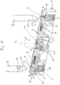
- eine perspektivische Ansicht eines erfindungsgemäß aufgebauten Schloßkörpers und erfindungsgemäß einsetzbarer Bügelenden,
- Fig. 2
- die Ansicht einer geöffneten Gehäusehälfte eines Schlosses gemäß Fig. 1 in der Verriegelungsstellung, und
- Fig. 3
- eine Ansicht gemäß Fig. 2 in einer geöffneten Bereitschaftsstellung des Schlosses.
- Fig. 1
- 2 shows a perspective view of a lock body constructed according to the invention and shackle ends that can be used according to the invention,
- Fig. 2
- the view of an open housing half of a lock according to FIG. 1 in the locked position, and
- Fig. 3
- a view of FIG. 2 in an open standby position of the castle.
Fig. 1 zeigt einen Schloßkörper 1, welcher mit zwei im wesentlichen zylindrischen Bügelaufnahmen 2 versehen ist.Fig. 1 shows a lock body 1, which with two essentially cylindrical bracket receptacles 2 is provided.
Aus Gründen der Übersichtlichkeit ist in Fig. 1 eine
Betriebsstellung des Schlosses gezeigt, welche in der Praxis
nicht gegeben sein kann. Das Mitnehmer-Sperrelement 15 ist
in einer Position gezeichnet, in der es sich bei eingeführtem
Bügel 9 befindet. Ebenso entspricht die Stellung der
Riegel 6 sowie des Mitnehmers 12 der Betriebsstellung bei im
Schloßkörper 1 verriegeltem Bügel 9, bei dem der Mitnehmer
12 der Riegel 6 blockiert. Die Bügelbeaufschlagungsmittel
3, 4 befinden sich in einer Stellung, in der sie bei vom
Schloßkörper 1 gelöstem Bügel 9 zu liegen kommen.1 for reasons of clarity
Operating position of the lock shown, which in practice
cannot be given. The
Das in Fig. 1 dargestellte Schloß wird wie folgt beschrieben:The lock shown in Fig. 1 is described as follows:
Am unteren Ende der beiden Bügelaufnahmen 2 ist jeweils eine
Druckfeder 3 angeordnet, an deren oberen Enden jeweils eine
Bügel-Kontaktscheibe 4 vorgesehen ist, die im wesentlichen
Kreisringform aufweist.At the lower end of the two bracket receptacles 2 is one
In der in Fig. 1 dargestellten Position liegen die Bügel-Kontaktscheiben
4 an einem in den Bügelaufnahmen 2 vorgesehenen
Flansch 5 an, welcher verhindert, daß Druckfeder 3 und Bügelkontaktscheibe
4 sich aus dem dafür vorgesehenen Bereich
der Bügelaufnahme 2 herausbewegen können.In the position shown in Fig. 1, the bracket contact disks are
4 on one provided in the bracket receptacles 2
Quer zu den Achsen der Bügelaufnahmen 2 erstrecken sich im
Schloßkörper 1 in entgegengesetzten Richtungen zwei Riegel
6, die mittels jeweils einer Druckfeder 7 in ihre Verriegelungsstellung
vorgespannt sind. Die Vorspannung der Riegel 6
ist durch die Pfeile A veranschaulicht.Transverse to the axes of the bracket receptacles 2 extend in the
Lock body 1 in opposite directions two
In ihren den Bügelaufnahmen 2 zugewandten Endbereichen weisen
die Riegel 6 im wesentlichen Streifenform auf, wobei die
Endbereiche der Riegel 6 umgebogen sind. Der Biegewinkel beträgt
hierbei 180°.Point in their end regions facing the bracket receptacles 2
the
Durch die umgebogenen Enden der Riegel 6 wird erreicht, daß
der in der Verriegelungsstellung in die Bügelaufnahmen 2
hineinragende Bereich der Riegel 6 einen abgerundeten Endbereich
8 aufweist, welcher auf die bereits erläuterte Weise
das Einführen der Bügelenden in die Bügelaufnahmen 2 erleichtert.The bent ends of the
In Fig. 1 sind oberhalb der Bügelaufnahmen 2 die Endbereiche
eines Bügels 9 dargestellt, der im Querschnitt kreisförmig
ist.In Fig. 1, the end regions are above the bracket receptacles 2
shown a
Beide Bügelenden weisen jeweils eine Ausnehmung 10 auf, wobei
beide Ausnehmungen 10 jeweils auf der Innenseite des Bügels
9 angeordnet sind. Both temple ends each have a
Die Ausnehmungen 10 sind komplementär zu den Endbereichen
der Riegel 6 ausgebildet, so daß in den Ausnehmungen 10 die
Endbereiche der Riegel 6 in ihrer Verriegelungsstellung zu
liegen kommen können.The
Der unterhalb der Ausnehmungen 10 liegende Endbereich des
Bügels 9 ist jeweils kegelstumpfförmig ausgebildet, wobei
die Mantelfläche dieses kegelstumpfförmigen Bereichs die
erfindungsgemäße Verdrängungsfläche 11 zur Betätigung der
Riegel 6 bildet.The end region of the
Im Zentralbereich des Schloßkörpers 1 ist ein länglicher Mitnehmer
12 vorgesehen, welcher mittels einer nicht dargestellten
Spiralfeder in seine in Fig. 1 gezeichnete Position entsprechend
Pfeil B vorgespannt ist.In the central area of the lock body 1 is an
Der Mitnehmer 12 ist durch einen in Fig. 1 aus Gründen der
Übersichtlichkeit nicht dargestellten Schließzylinder betätig- und um die Achse C drehbar. Die Achse C erstreckt sich
dabei parallel zu den Enden des Bügels 9 und zu den Längsachsen
der Bügelaufnahmen 2.The
Der Mitnehmer 12 besitzt an seinen Schmalseiten jeweils eine
Blockierfläche 13, die in der in Fig. 1 dargestellten Position
eine Bewegung der Riegel 6 aus der Verriegelungsstellung
in die Entriegelungsstellung unmöglich macht.The
Bei Betätigung des Mitnehmers über den Schließzylinder in
seine Entriegelungsstellung kommt der Mitnehmer 12 zur Anlage
mit einer an den Riegeln 6 jeweils ausgebildeten Mitnehmerlasche
14, über die der Mitnehmer 12 den Riegel 6 entgegen
der durch die Druckfedern 7 bewirkten Vorspannung in seine
Entriegelungsstellung bewegt. When the driver is actuated via the locking cylinder in
the
Unterhalb eines der beiden Riegel 6 ist ein Mitnehmer-Sperrelement
15 vorgesehen, welches in Fig. 1 in derjenigen Position
gezeichnet ist, in der es sich bei in den Bügelaufnahmen
2 verriegeltem Bügel befinden würde.Below one of the two
Das Mitnehmer-Sperrelement 15 ist durch eine nicht dargestellte
Druckfeder in Richtung des Pfeiles D vorgespannt und
weist an seinem im Bereich der Bügelaufnahme 2 liegenden
Ende eine ösenförmige Öffnung 16 auf, die so bemessen ist,
daß die Bügelenden durch diese Öffnung 16 hindurchbewegt
werden können.The
An seinem der Öffnung 16 abgewandten Ende ist das Mitnehmer-Sperrelement
15 mit einem Sperrbereich 17 versehen, welcher
bei in Richtung des Pfeiles D verschobenem Mitnehmer-Sperrelement
den Mitnehmer 13 in seiner in Fig. 1 dargestellten
Position hält.At its end facing away from the
Das in Fig. 1 dargestellte Bügelschloß funktioniert wie folgt:The U-lock shown in Fig. 1 works like follows:
In der in Fig. 2 gezeigten verriegelten Stellung des erfindungsgemäßen
Bügelschlosses ist der Bügel 9 mit seinen beiden
Enden 11 in den Schloßkörper 1 eingeführt.In the locked position of the invention shown in Fig. 2
U-lock is the
Dabei greift der untere Endbereich des kegelförmigen Endes
der beiden Bügelschenkel in das in der Mitte der Bügel-Kontaktscheibe
4 ausgebildete Loch ein. Durch die Bügelenden 9
wird die Bügel-Kontaktscheibe 4 entgegen der durch die Feder
3 bewirkten Vorspannung nach unten verschoben. In dieser Verriegelungsstellung
steht die Bügel-Kontaktscheibe 4 also unter
einer erhöhten, durch die Druckfeder 3 bewirkten Vorspannung,
welche beim Entriegeln in Richtung einer Lösung des
Bügels 9 vom Schloßkörper 1 wirkt. The lower end area of the conical end engages
the two stirrup legs in the middle of the
Die abgerundeten Endbereiche 8 der Riegel 6 greifen in der
in Fig. 2 dargestellten Verriegelungsstellung in die Ausnehmungen
10 der beiden Bügelenden 9 ein und verriegeln auf diese
Weise den Bügel 9 im Schloßkörper 1. Eine unerwünschte Bewegung
der Riegel 6 aus den Ausnehmungen 10 wird dabei durch
den in seiner Verriegelungsstellung befindlichen Mitnehmer
12 blockiert. Die Stellung des Mitnehmers 12 gemäß Fig. 2
entspricht der in Fig. 1 gezeichneten Position.The
Ebenso entspricht die Position des Mitnehmer-Sperrelements
15 gemäß Fig. 2 der in Fig. 1 gezeichneten Position, so daß
der Mitnehmer 12 in der in Fig. 2 dargestellten Verriegelungsposition
nicht durch das Mitnehmer-Sperrelement 15
blockiert, sondern entgegen seiner Vorspannung frei beweglich
ist. So kann das Schloß mittels eines in Fig. 2 aus
Gründen der Übersichtlichkeit nicht dargestellten Schlüssels
aufgeschlossen werden, indem mittels des genannten Schlüssels
der Mitnehmer 12 beispielsweise um 90° in eine Öffnungsstellung
verdreht werden kann.The position of the driver blocking element also corresponds
15 of FIG. 2 of the position shown in FIG. 1, so that
the
In der in Fig. 2 dargestellten Position sind alle beweglichen
Teile des Schlosses, insbesondere die Bügel-Kontaktscheiben
4, die Riegel 6, der Mitnehmer 12 sowie das Mitnehmer-Sperrelement
15 mittels entsprechender Federn vorgespannt,
so daß hier bei Erschütterungen des Schlosses keine
störenden Geräusche auftreten können.In the position shown in Fig. 2, all are movable
Parts of the lock, especially the
Wenn nun das Schloß mittels eines Schlüssels aufgesperrt werden
soll, wird der Mitnehmer 12 im Vergleich zu der in Fig.
1 und 2 dargestellten Position um 90° verdreht, wodurch der
Mitnehmer 12 die beiden Mitnehmerlaschen 14 linear in einer
Weise bewegt, daß die Riegel 6 entgegen der durch die Druckfedern
7 bewirkten Vorspannung aus den Ausnehmungen 10 des
Bügels 9 herausbewegt werden. If the lock is now unlocked using a key
should, the
Sobald die Riegel 6 den Bügel 9 freigeben, entspannen sich
die Druckfedern 3 und bewirken dadurch eine Aufwärtsbewegung
der Bügel-Kontaktscheiben 4.As soon as the
Durch diese Aufwärtsbewegung der Bügel-Kontaktscheiben 4
wird der Bügel 9 nach oben aus dem Schloßkörper 1 herausgedrückt,
und das durch die Druckfeder 18 ebenfalls unter Vorspannung
gesetzte Mitnehmer-Sperrelement 15 bewegt sich in
die in Fig. 3 dargestellte Position, da es durch den Bügel 9
nicht mehr in der in den Fig. 1 und 2 dargestellten Position
gehalten wird. In der in Fig. 3 gezeigten Position des Mitnehmer-Sperrelements
15 blockiert dieses den Mitnehmer 14
nach dem Entriegelungsvorgang in einer Bereitschaftsstellung,
so daß die Riegel 6 weiterhin entgegen ihrer Vorspannung
frei beweglich sind und bei einem neuerlichen Einführen
des Bügels 9 nicht blockiert, sondern durch die Verdrängungsflächen
11 verschiebbar sind.This upward movement of the
Fig. 3 zeigt die Position des erfindungsgemäßen Schlosses,
nachdem der Bügel 9 vom Schloßkörper 1 gelöst und der Schlüssel
aus dem nicht dargestellten, mit dem Mitnehmer 12 in
Wirkverbindung stehenden Schließzylinder abgezogen wurde.
Diese Position kann als Bereitschaftsstellung bezeichnet
werden.3 shows the position of the lock according to the invention,
after the
In dieser Position befinden sich die Riegel 6 in ihrer Verriegelungsstellung,
sind jedoch - da sie durch die Mitnehmer
12 nicht blockiert sind - in ihre Entriegelungsposition verschiebbar.
Der Mitnehmer 12 ist in der Bereitschaftsstellung
gegenüber seiner in Fig.1 gezeigten Position um ungefähr 45°
entgegen dem Uhrzeigersinn verdreht und wird vom Mitnehmer-Sperrelement
15 in dieser Position gehalten. In this position the
Die Bügel-Kontaktscheiben 4 befinden sich in der in Fig. 3
dargestellten Position in ihrer oberen Anschlagsstellung, in
der sie am jeweiligen Flansch 5 anliegen.The
Auch in der in Fig. 3 dargestellten Position sind alle beweglichen
Teile des Schlosses, insbesondere die Bügel-Kontaktscheiben
4, die Riegel 6, der Mitnehmer 12 sowie das Mitnehmer-Sperrelement
15 mittels der genannten Federn vorgespannt,
so daß auch hier bei Erschütterungen des Schlosses
keine störenden Geräusche auftreten können.Also in the position shown in Fig. 3, all are movable
Parts of the lock, especially the
Wenn nun ausgehend von der in Fig. 3 dargestellten Position
der Bügel 9 wiederum in den Schloßkörper 1 eingeführt wird,
werden die Riegel 6 durch die gegenseitige Berührung von deren
abgerundeten Endbereichen 8 und den Verdrängungsflächen
11 des Bügels 9 in ihre Entriegelungsposition verschoben.
Gleichzeitig bewirkt die Verdrängungsfläche 11 des linken
Bügelendes, welches in die Öffnung 16 des Mitnehmer-Sperrelements
15 eindringt, eine Verschiebung des Mitnehmer-Sperrelements
in die in Fig. 1 und 2 dargestellte Position, in der
der Mitnehmer 12 entgegen seiner Vorspannung beweglich ist,
so daß er mittels des Schlüssels bzw. des Schließzylinders
beaufschlagbar ist.If now starting from the position shown in Fig. 3
the
Gleichzeitig werden beim Einführen des Bügels 9 die Federn 3
gestaucht und die Bügel-Kontaktscheiben nach unten verschoben,
bis sie sich in der in Fig. 2 dargestellten Position befinden.
In dieser Position schnappen dann die Riegel 6 in
die Ausnehmungen 10 des Bügels 9 ein, werden durch den
Mitnehmer 12 blockiert und das Schloß ist verriegelt.At the same time, when the
Claims (16)
dadurch gekennzeichnet,
characterized by
dadurch gekennzeichnet,
characterized by
dadurch gekennzeichnet,
characterized by
dadurch gekennzeichnet,
characterized by
dadurch gekennzeichnet,
characterized by
dadurch gekennzeichnet,
characterized by
dadurch gekennzeichnet,
characterized by
dadurch gekennzeichnet,
characterized by
dadurch gekennzeichnet,
characterized by
dadurch gekennzeichnet,
characterized by
dadurch gekennzeichnet,
characterized by
dadurch gekennzeichnet,
characterized by
dadurch gekennzeichnet,
characterized by
dadurch gekennzeichnet,
characterized by
dadurch gekennzeichnet,
characterized by
dadurch gekennzeichnet,
characterized by
Applications Claiming Priority (2)
| Application Number | Priority Date | Filing Date | Title |
|---|---|---|---|
| DE19638188A DE19638188A1 (en) | 1996-09-18 | 1996-09-18 | U-lock |
| DE19638188 | 1996-09-18 |
Publications (2)
| Publication Number | Publication Date |
|---|---|
| EP0831198A1 true EP0831198A1 (en) | 1998-03-25 |
| EP0831198B1 EP0831198B1 (en) | 2003-03-26 |
Family
ID=7806093
Family Applications (1)
| Application Number | Title | Priority Date | Filing Date |
|---|---|---|---|
| EP97115634A Expired - Lifetime EP0831198B1 (en) | 1996-09-18 | 1997-09-09 | Padlock |
Country Status (2)
| Country | Link |
|---|---|
| EP (1) | EP0831198B1 (en) |
| DE (2) | DE19638188A1 (en) |
Cited By (2)
| Publication number | Priority date | Publication date | Assignee | Title |
|---|---|---|---|---|
| DE102007035122A1 (en) * | 2007-07-27 | 2009-01-29 | ABUS August Bremicker Söhne KG | lock |
| EP3591147A1 (en) * | 2018-07-06 | 2020-01-08 | ABUS August Bremicker Söhne KG | Bicycle lock with alarm function |
Families Citing this family (4)
| Publication number | Priority date | Publication date | Assignee | Title |
|---|---|---|---|---|
| FR2982302B1 (en) * | 2011-11-09 | 2014-11-07 | Thirard Ets | ELECTROMECHANICAL LATCH |
| DE102013114055B4 (en) * | 2013-12-13 | 2016-02-04 | Sheng Yung Lock Industrial Co., Ltd. | Lock with a separable latch |
| WO2015192013A1 (en) * | 2014-06-12 | 2015-12-17 | Schlage Lock Company Llc | Hoop lock with dual locking |
| CN112539004B (en) * | 2020-12-10 | 2023-01-31 | 潘永旺 | U-shaped lock |
Citations (5)
| Publication number | Priority date | Publication date | Assignee | Title |
|---|---|---|---|---|
| US2433114A (en) * | 1945-10-22 | 1947-12-23 | Illinois Lock Co | Padlock |
| US4621509A (en) * | 1983-10-20 | 1986-11-11 | Kabushiki Kaisha Saikousha | Combination locking device having removable U-shaped retaining rod |
| EP0550412A2 (en) * | 1988-05-06 | 1993-07-07 | Aug. Winkhaus GmbH & Co. KG | Padlock |
| US5394712A (en) * | 1994-01-11 | 1995-03-07 | Nigostar Industry Co., Ltd. | Motorcycle lock |
| NL9401601A (en) * | 1994-09-29 | 1996-05-01 | Chen Kuei Hsieh | U-Shaped padlock |
Family Cites Families (4)
| Publication number | Priority date | Publication date | Assignee | Title |
|---|---|---|---|---|
| DE9013187U1 (en) * | 1990-09-17 | 1991-05-23 | Aug. Winkhaus Gmbh & Co Kg, 4404 Telgte, De | |
| DE4329511A1 (en) * | 1993-09-01 | 1995-03-02 | Winkhaus Fa August | Long shackle lock with self-locking clamping of a bolt element |
| US5417092A (en) * | 1994-06-02 | 1995-05-23 | Iu; Chien-Chzh | Padlock |
| DE29520227U1 (en) * | 1995-12-20 | 1996-02-29 | Rerlly Industry Co | Lock, especially for motorcycles |
-
1996
- 1996-09-18 DE DE19638188A patent/DE19638188A1/en not_active Withdrawn
-
1997
- 1997-09-09 EP EP97115634A patent/EP0831198B1/en not_active Expired - Lifetime
- 1997-09-09 DE DE59709608T patent/DE59709608D1/en not_active Expired - Fee Related
Patent Citations (5)
| Publication number | Priority date | Publication date | Assignee | Title |
|---|---|---|---|---|
| US2433114A (en) * | 1945-10-22 | 1947-12-23 | Illinois Lock Co | Padlock |
| US4621509A (en) * | 1983-10-20 | 1986-11-11 | Kabushiki Kaisha Saikousha | Combination locking device having removable U-shaped retaining rod |
| EP0550412A2 (en) * | 1988-05-06 | 1993-07-07 | Aug. Winkhaus GmbH & Co. KG | Padlock |
| US5394712A (en) * | 1994-01-11 | 1995-03-07 | Nigostar Industry Co., Ltd. | Motorcycle lock |
| NL9401601A (en) * | 1994-09-29 | 1996-05-01 | Chen Kuei Hsieh | U-Shaped padlock |
Cited By (6)
| Publication number | Priority date | Publication date | Assignee | Title |
|---|---|---|---|---|
| DE102007035122A1 (en) * | 2007-07-27 | 2009-01-29 | ABUS August Bremicker Söhne KG | lock |
| US8127577B2 (en) | 2007-07-27 | 2012-03-06 | Abus August Bremicker Soehne Kg | Lock |
| EP3591147A1 (en) * | 2018-07-06 | 2020-01-08 | ABUS August Bremicker Söhne KG | Bicycle lock with alarm function |
| CN110685513A (en) * | 2018-07-06 | 2020-01-14 | Abus·奥古斯特·布莱梅克·索恩有限股份两合公司 | Two-wheel lock with alarm function |
| CN110685513B (en) * | 2018-07-06 | 2022-04-26 | Abus·奥古斯特·布莱梅克·索恩有限股份两合公司 | Two-wheel lock with alarm function |
| US11447976B2 (en) | 2018-07-06 | 2022-09-20 | ABUS August Bremicker Söhne KG | Two-wheeler lock having an alarm function |
Also Published As
| Publication number | Publication date |
|---|---|
| EP0831198B1 (en) | 2003-03-26 |
| DE59709608D1 (en) | 2003-04-30 |
| DE19638188A1 (en) | 1998-03-19 |
Similar Documents
| Publication | Publication Date | Title |
|---|---|---|
| DE3906473C2 (en) | Locking device | |
| WO2002029185A1 (en) | Tool for releasing a locking cylinder | |
| EP0369107A2 (en) | Cylinder lock | |
| DE2942789C2 (en) | Permutation lock | |
| DE2441463C3 (en) | Cylinder lock with an axially displaceable cylinder core, especially for a steering lock in motor vehicles | |
| DE4408024C5 (en) | safety switch | |
| EP1171895B1 (en) | Blocking device for a switch mechanism | |
| DE3717778C2 (en) | ||
| DE3126761A1 (en) | PERMUTATION LOCK | |
| EP2993090B1 (en) | Steering wheel locking system | |
| DE102011050226A1 (en) | Locking actuator for wing of frame of e.g. door, has primary operating element comprising lever and pivotably attached at wing around pivotal axis that runs parallel to plane of wing and perpendicular to longitudinal direction of bar | |
| EP0831198B1 (en) | Padlock | |
| EP1637679A1 (en) | Padlock, in particular for bicycles | |
| DE69909676T2 (en) | Steering wheel lock device for vehicle steering | |
| DE2931698A1 (en) | PERMUTATION LOCK, ESPECIALLY FOR BAGS AND CASES | |
| DE2743769A1 (en) | LOCK AND CODED KEY TO OPERATE THE LOCK | |
| EP0434922B1 (en) | Storage holder for magnetic tape cassette | |
| DE202007016091U1 (en) | Espagnolette | |
| EP0428029B1 (en) | Lock | |
| EP1785558B1 (en) | Lock, in particular for safe | |
| DE2322330C3 (en) | Motor vehicle steering lock | |
| DE2047702C3 (en) | Anti-theft devices for motor vehicles | |
| CH671603A5 (en) | ||
| DE3421094A1 (en) | SAFETY LOCK | |
| WO2001061130A1 (en) | Locking system, especially for motor vehicles |
Legal Events
| Date | Code | Title | Description |
|---|---|---|---|
| PUAI | Public reference made under article 153(3) epc to a published international application that has entered the european phase |
Free format text: ORIGINAL CODE: 0009012 |
|
| AK | Designated contracting states |
Kind code of ref document: A1 Designated state(s): DE FR NL SE |
|
| AX | Request for extension of the european patent |
Free format text: AL;LT;LV;RO;SI |
|
| 17P | Request for examination filed |
Effective date: 19980902 |
|
| AKX | Designation fees paid |
Free format text: DE FR NL SE |
|
| RBV | Designated contracting states (corrected) |
Designated state(s): DE FR NL SE |
|
| 17Q | First examination report despatched |
Effective date: 20010831 |
|
| GRAH | Despatch of communication of intention to grant a patent |
Free format text: ORIGINAL CODE: EPIDOS IGRA |
|
| GRAH | Despatch of communication of intention to grant a patent |
Free format text: ORIGINAL CODE: EPIDOS IGRA |
|
| GRAA | (expected) grant |
Free format text: ORIGINAL CODE: 0009210 |
|
| AK | Designated contracting states |
Designated state(s): DE FR NL SE |
|
| REF | Corresponds to: |
Ref document number: 59709608 Country of ref document: DE Date of ref document: 20030430 Kind code of ref document: P |
|
| REG | Reference to a national code |
Ref country code: SE Ref legal event code: TRGR |
|
| PGFP | Annual fee paid to national office [announced via postgrant information from national office to epo] |
Ref country code: NL Payment date: 20030917 Year of fee payment: 7 |
|
| PGFP | Annual fee paid to national office [announced via postgrant information from national office to epo] |
Ref country code: FR Payment date: 20030918 Year of fee payment: 7 |
|
| PGFP | Annual fee paid to national office [announced via postgrant information from national office to epo] |
Ref country code: SE Payment date: 20030923 Year of fee payment: 7 |
|
| PGFP | Annual fee paid to national office [announced via postgrant information from national office to epo] |
Ref country code: DE Payment date: 20031016 Year of fee payment: 7 |
|
| ET | Fr: translation filed | ||
| PLBE | No opposition filed within time limit |
Free format text: ORIGINAL CODE: 0009261 |
|
| STAA | Information on the status of an ep patent application or granted ep patent |
Free format text: STATUS: NO OPPOSITION FILED WITHIN TIME LIMIT |
|
| 26N | No opposition filed |
Effective date: 20031230 |
|
| PG25 | Lapsed in a contracting state [announced via postgrant information from national office to epo] |
Ref country code: SE Free format text: LAPSE BECAUSE OF NON-PAYMENT OF DUE FEES Effective date: 20040910 |
|
| PG25 | Lapsed in a contracting state [announced via postgrant information from national office to epo] |
Ref country code: NL Free format text: LAPSE BECAUSE OF NON-PAYMENT OF DUE FEES Effective date: 20050401 Ref country code: DE Free format text: LAPSE BECAUSE OF NON-PAYMENT OF DUE FEES Effective date: 20050401 |
|
| EUG | Se: european patent has lapsed | ||
| PG25 | Lapsed in a contracting state [announced via postgrant information from national office to epo] |
Ref country code: FR Free format text: LAPSE BECAUSE OF NON-PAYMENT OF DUE FEES Effective date: 20050531 |
|
| NLV4 | Nl: lapsed or anulled due to non-payment of the annual fee |
Effective date: 20050401 |
|
| REG | Reference to a national code |
Ref country code: FR Ref legal event code: ST |