EP3591147A1 - Bicycle lock with alarm function - Google Patents
Bicycle lock with alarm function Download PDFInfo
- Publication number
- EP3591147A1 EP3591147A1 EP19184447.1A EP19184447A EP3591147A1 EP 3591147 A1 EP3591147 A1 EP 3591147A1 EP 19184447 A EP19184447 A EP 19184447A EP 3591147 A1 EP3591147 A1 EP 3591147A1
- Authority
- EP
- European Patent Office
- Prior art keywords
- locking
- lock
- locking mechanism
- bracket
- alarm
- Prior art date
- Legal status (The legal status is an assumption and is not a legal conclusion. Google has not performed a legal analysis and makes no representation as to the accuracy of the status listed.)
- Granted
Links
- 230000007246 mechanism Effects 0.000 claims abstract description 139
- 230000004913 activation Effects 0.000 claims abstract description 43
- 230000001133 acceleration Effects 0.000 claims description 14
- 238000011156 evaluation Methods 0.000 claims description 11
- 230000005540 biological transmission Effects 0.000 claims description 8
- 230000000007 visual effect Effects 0.000 claims description 4
- 238000003780 insertion Methods 0.000 description 14
- 230000037431 insertion Effects 0.000 description 14
- 230000008859 change Effects 0.000 description 9
- 230000001681 protective effect Effects 0.000 description 6
- 238000001514 detection method Methods 0.000 description 5
- 230000003287 optical effect Effects 0.000 description 5
- 238000012544 monitoring process Methods 0.000 description 4
- 230000036316 preload Effects 0.000 description 4
- 230000003213 activating effect Effects 0.000 description 3
- 238000012790 confirmation Methods 0.000 description 3
- 235000014676 Phragmites communis Nutrition 0.000 description 2
- 238000013461 design Methods 0.000 description 2
- 239000000463 material Substances 0.000 description 2
- 239000002184 metal Substances 0.000 description 2
- 230000003068 static effect Effects 0.000 description 2
- 239000003086 colorant Substances 0.000 description 1
- 230000001419 dependent effect Effects 0.000 description 1
- 230000017027 detection of gravity Effects 0.000 description 1
- 230000000694 effects Effects 0.000 description 1
- 238000000034 method Methods 0.000 description 1
- 239000011295 pitch Substances 0.000 description 1
- 230000008569 process Effects 0.000 description 1
- 230000009467 reduction Effects 0.000 description 1
- 230000008054 signal transmission Effects 0.000 description 1
- 230000036962 time dependent Effects 0.000 description 1
- 230000001960 triggered effect Effects 0.000 description 1
- 238000009423 ventilation Methods 0.000 description 1
Images


Classifications
-
- E—FIXED CONSTRUCTIONS
- E05—LOCKS; KEYS; WINDOW OR DOOR FITTINGS; SAFES
- E05B—LOCKS; ACCESSORIES THEREFOR; HANDCUFFS
- E05B45/00—Alarm locks
- E05B45/005—Chain-locks, cable-locks or padlocks with alarms
-
- E—FIXED CONSTRUCTIONS
- E05—LOCKS; KEYS; WINDOW OR DOOR FITTINGS; SAFES
- E05B—LOCKS; ACCESSORIES THEREFOR; HANDCUFFS
- E05B67/00—Padlocks; Details thereof
- E05B67/06—Shackles; Arrangement of the shackle
- E05B67/22—Padlocks with sliding shackles, with or without rotary or pivotal movement
- E05B67/24—Padlocks with sliding shackles, with or without rotary or pivotal movement with built- in cylinder locks
-
- E—FIXED CONSTRUCTIONS
- E05—LOCKS; KEYS; WINDOW OR DOOR FITTINGS; SAFES
- E05B—LOCKS; ACCESSORIES THEREFOR; HANDCUFFS
- E05B45/00—Alarm locks
- E05B45/06—Electric alarm locks
-
- E—FIXED CONSTRUCTIONS
- E05—LOCKS; KEYS; WINDOW OR DOOR FITTINGS; SAFES
- E05B—LOCKS; ACCESSORIES THEREFOR; HANDCUFFS
- E05B47/00—Operating or controlling locks or other fastening devices by electric or magnetic means
- E05B47/0001—Operating or controlling locks or other fastening devices by electric or magnetic means with electric actuators; Constructional features thereof
- E05B47/0012—Operating or controlling locks or other fastening devices by electric or magnetic means with electric actuators; Constructional features thereof with rotary electromotors
-
- E—FIXED CONSTRUCTIONS
- E05—LOCKS; KEYS; WINDOW OR DOOR FITTINGS; SAFES
- E05B—LOCKS; ACCESSORIES THEREFOR; HANDCUFFS
- E05B67/00—Padlocks; Details thereof
- E05B67/06—Shackles; Arrangement of the shackle
- E05B67/063—Padlocks with removable shackles
-
- E—FIXED CONSTRUCTIONS
- E05—LOCKS; KEYS; WINDOW OR DOOR FITTINGS; SAFES
- E05B—LOCKS; ACCESSORIES THEREFOR; HANDCUFFS
- E05B71/00—Locks specially adapted for bicycles, other than padlocks
-
- E—FIXED CONSTRUCTIONS
- E05—LOCKS; KEYS; WINDOW OR DOOR FITTINGS; SAFES
- E05B—LOCKS; ACCESSORIES THEREFOR; HANDCUFFS
- E05B45/00—Alarm locks
- E05B45/06—Electric alarm locks
- E05B2045/065—Switch or sensor type used in alarm locks
- E05B2045/0665—Magnetic switches, e.g. reed- or hall-switch
-
- E—FIXED CONSTRUCTIONS
- E05—LOCKS; KEYS; WINDOW OR DOOR FITTINGS; SAFES
- E05B—LOCKS; ACCESSORIES THEREFOR; HANDCUFFS
- E05B47/00—Operating or controlling locks or other fastening devices by electric or magnetic means
- E05B47/0001—Operating or controlling locks or other fastening devices by electric or magnetic means with electric actuators; Constructional features thereof
Definitions
- the present invention relates to a lock with an alarm function for a two-wheeler, with a lock body and a securing bracket which can be moved relative to the lock body between a securing position for securing the two-wheeler and an open position for releasing the two-wheeler, the lock body having a locking mechanism to prevent the Locking the safety bracket in the locking position optionally on the lock body, the lock body further comprising an alarm device for outputting an alarm signal.
- Such a lock can be designed, for example, as a U-bracket lock, which has a rigid, essentially U-shaped securing bracket, or as an articulated lock with an articulated rod as a securing bracket, which has a plurality of pivoting rods which are pivotally connected to one another.
- a two-wheel lock of the type mentioned can also be designed as a so-called frame lock, in which a rotating bracket or swivel bracket engages between the spokes of one of the wheels of a bicycle.
- such a lock can be designed, for example, as a brake disc lock, in which the securing bracket engages in a ventilation opening of a brake disc of a motorcycle or a motor scooter.
- the securing bracket can also be flexible, for example in the form of a chain or a wire rope, which can optionally be locked on the lock body.
- a lock of the type mentioned is used, for example, to secure a two-wheeler to a bicycle stand, a lamppost or another stationary object, or to secure a two-wheeler against unauthorized driving away.
- the securing bracket When the securing bracket is unlocked, the securing bracket can be brought into an open position in which the securing bracket is released from the lock body at one end or completely. Starting from the open position, the securing bracket can be guided, for example, around a frame section of the two-wheeler and a bicycle stand, lamppost or the like, or the securing bracket is only guided through a movable part (e.g. rim, brake disc) of the two-wheeler. The safety bracket can then be (completely) closed and locked on the lock body, in order to secure the two-wheeler against unauthorized removal or unauthorized driving away.
- the safety bracket can be unlocked by the authorized user actuating the locking mechanism of the lock by means of an assigned key or other identification means (e.g. transponder).
- An alarm device that is sensitive to vibrations, for example, must not trigger the output of an alarm signal during the transport of the lock, and activation of the alarm device is not desirable each time the bicycle is locked (e.g. securing the bicycle to a bicycle rack of a motor vehicle).
- a two-wheel lock with an alarm function with the features of claim 1, and in particular in that the locking mechanism can be brought optionally into an unlocking position, a locking position or an alarm activation position, the locking bracket being released for movement into the open position in the unlocking position , wherein in the locking position the locking bracket located in the locking position is locked to the lock body, and wherein the alarm device can be activated or activated by moving the locking mechanism into the alarm activation position.
- the locking mechanism can also - at least temporarily - be brought into an alarm activation position.
- the alarm device of the two-wheel lock can be activated as long as the locking mechanism is in the alarm activation position. Provision can also be made for the alarm device to be activated by temporarily moving the locking mechanism into the alarm activation position, the alarm device being able to remain activated even if the locking mechanism is immediately moved to another position.
- the alarm activation position can form a further (i.e. second) locking position with regard to the locking mechanism, as will be explained below.
- actuation of the locking mechanism of the two-wheel lock by the authorized user is provided in any case, in particular for unlocking or locking, for example by means of an assigned key, by means of an electronic identification means, by transmission a code or a combination thereof.
- actuation of the locking mechanism namely by placing the locking mechanism in an alarm activation position
- the authorized user can not only select the locking state or unlocking state of the locking mechanism, but also determine whether or not the alarm device should be activated or activated.
- the alarm activation position can be determined indirectly (for example from a control signal for the locking mechanism) or directly (for example by a position detector). This results in a comfortable and, in particular, also fail-safe operation of the two-wheel lock and in particular the alarm device.
- the two-wheel lock can be configured such that the alarm device is automatically activated by moving the locking mechanism into the alarm activation position.
- the locking mechanism is designed to be purely mechanical.
- the locking mechanism can have a locking cylinder which can be rotated by means of a key.
- the locking cylinder can be directly or indirectly coupled to one or more bolts to release the locking bracket in the unlocked position and to lock the locking bracket (if it is in the locking position) to the lock body in the locking position.
- the alarm device by turning the lock cylinder by means of the key, the alarm device can be activated directly or indirectly by turning the lock cylinder into a Alarm activation position is brought, which differs from the unlocking position and the locking position or a first locking position.
- the locking cylinder can have a cylinder housing and a cylinder core rotatably mounted in the cylinder housing, the locking position of the locking mechanism corresponding to a first rotational position of the cylinder core, the alarm activation position of the locking mechanism corresponding to a second rotational position of the cylinder core, and the unlocking position of the locking mechanism of a third rotational position corresponds to the cylinder core.
- the user can easily differentiate the different positions or states of the locking mechanism from one another and select them without incorrect operation.
- the locking cylinder can be actuated from the unlocking position in a first direction of rotation or in a second direction of rotation opposite thereto.
- the unlocking position thus forms a central position for the actuation of the locking cylinder in order to bring the locking mechanism or the locking cylinder optionally into another position.
- the locking cylinder can be actuated from the locking position in a first direction of rotation or in a second direction of rotation opposite thereto. The locking position thus forms a central position for the actuation of the locking cylinder.
- the first rotational position, the second rotational position and the third rotational position of the cylinder core can each be offset by 90 ° to one another. This provides the user with a clear, clearly visible distinction between the different rotational positions in order to be able to operate the locking mechanism without errors.
- the first rotational position of the cylinder core with respect to the third rotational position of the cylinder core by an angle of 90 ° the second rotational position of the cylinder core with respect to the third rotational position of the cylinder core by an angle of 90 ° and with respect to the first rotational position of the cylinder core by an angle of 180 ° ,
- the key can be inserted into the cylinder core in two different positions of the cylinder core and can be removed from the cylinder core.
- two different positions of the locking mechanism can be selected, in which the assigned key can be removed from the locking cylinder.
- These two different positions can in particular be two locking positions in order to lock the safety bracket on the lock body (when the alarm device is activated or the alarm device is deactivated).
- the assigned key can be inserted into the cylinder core and removed from the cylinder core both in the first rotational position of the cylinder core and in the second rotational position of the cylinder core.
- the lock cylinder can have a plurality of tumblers which are displaced by inserting the key into the cylinder core.
- a specific locking secret of the respective locking cylinder can be encoded by the multiple tumblers.
- the locking cylinder can be designed as a plate cylinder with a plurality of plate tumblers, as is generally the case, for example DE 102014108355 A1 is known.
- a plate cylinder enables a configuration in which the assigned key can be removed from the cylinder core in two different rotational positions, in particular offset by 180 ° to one another.
- the locking mechanism can have one or more bolts which lock the locking bracket, if this is in the securing position, on the lock body.
- the locking mechanism can have at least one bolt which can be driven by means of the associated key (in particular via a locking cylinder) and which engages with the securing bracket in the locking position of the locking mechanism in order to lock the securing bracket on the lock body.
- the bolt or another bolt that is drivable by means of the locking cylinder can engage the securing bracket in the alarm activation position of the locking mechanism.
- the alarm activation position can form a further locking position of the locking mechanism.
- the securing bracket may have at least one locking recess, with a latch engaging the locking recess when the locking mechanism is in the locking position (or another locking position). In the unlocked position of the locking mechanism, however, the respective latch does not engage in the associated locking recess (s) in the securing bracket.
- the respective locking recess can be designed, for example, as a groove or as a bore.
- the locking cylinder can be coupled to the at least one bolt via a deflection device which deflects a rotary movement of the locking cylinder into a linear movement of the bolt.
- the deflection devices can have at least one eccentric extension (eg pin), another type of cam, or a ramp, an associated one Counter element can be provided (eg guideway, backdrop or counter ramp).
- One element of the deflection device can be assigned to the locking cylinder and another element of the deflection device can be assigned to the respective bolt.
- the linear movement of the bolt can be a lateral, in particular radial, movement with respect to the axis of rotation of the locking cylinder, or an axial movement, in particular offset coaxially or parallel to the axis of rotation of the locking cylinder.
- a rotary movement or pivoting movement of the respective bolt can also be provided, the locking cylinder being able to be coupled to the at least one bolt directly or indirectly, in particular via a deflection device.
- the locking mechanism can be designed electromechanically in some embodiments.
- the locking mechanism can have an electric motor that serves as a servomotor, in particular to drive at least one bolt of the locking mechanism.
- an electric motor can be directly or indirectly coupled to one or more bolts to release the locking bracket in the unlocking position and to lock the locking bracket (if it is in the locking position) to the lock body in the locking position.
- the alarm device can be activated directly or indirectly by bringing the electric motor or a downstream drive element into an alarm activation position that differs from the unlocked position and the locked position or a first locked position.
- the locking mechanism can therefore have at least one bolt which can be driven electrically for a locking movement and / or an unlocking movement and which, in the locking position of the locking mechanism, engages with the securing bracket in order to lock the securing bracket on the lock body.
- the authorized user can actuate an electromechanical locking mechanism, for example, by means of an electronic identification means (e.g. transponder), by transmitting a code (e.g. by radio, in particular via a mobile terminal), by actuating a switch provided on the two-wheel lock or by a combination thereof ,
- an electronic identification means e.g. transponder
- a code e.g. by radio, in particular via a mobile terminal
- an electromechanical locking mechanism can have, for example, an electromagnetic drive device.
- the alarm activation position of the locking mechanism can form a further locking position, ie both in the locking position and in the alarm activation position, the securing bracket, insofar as it is in the securing position, can be locked on the lock body.
- the alarm device can be deactivated in one locking position, the alarm device being activated in the other locking position.
- the user in addition to the unlocking position, in which the alarm device can be deactivated, the user can select one of two different locking positions in which the safety bracket is equally mechanically locked (in particular purely mechanical or electromechanical), but the alarm device is either activated or deactivated.
- Such an embodiment is particularly suitable for a two-wheel lock with a so-called forced locking, in which the locking mechanism must be brought into a locking position in order to be able to remove an assigned key.
- the locking mechanism By actuating the locking mechanism by means of the assigned key for the purpose of locking the securing bracket, the user can thus not only bring about a desired mechanical locking, but can also select in a simple manner whether the alarm device should be activated or not.
- the securing bracket may have at least a first locking recess and at least a second locking recess, the securing bracket being locked to the first locking recess in the locking position of the locking mechanism, and the locking bracket being locked to the second locking recess in the further locking position of the locking mechanism.
- the locking mechanism can have two bolts, wherein in the locking position of the locking mechanism one of the two bolts engages in the first locking recess of the securing bracket, and in the further locking position of the locking mechanism the other of the two locking bolts engages in the second locking recess of the securing bracket.
- the securing bracket has a first bracket end and a second bracket end, each of which has a first locking recess and a second locking recess, wherein in the locking position of the locking mechanism, the one of the two bolts in the first locking recess of the first bracket end engages and the other of the two latches engages in the first locking recess of the second bracket end, and wherein in the further locking position of the locking mechanism one of the two latches engages in the second locking recess of the second bracket end and the other of the two latches in the second locking recess of the first bracket end intervenes.
- the locking mechanism can have only a single latch, which, starting from the unlocked position of the locking mechanism, is moved in the same direction regardless of the direction of a locking actuation of the locking mechanism (in particular regardless of the direction of a rotary actuation of a lock cylinder or electric motor).
- an actuation can take place in two different directions in order to move the locking mechanism into a respective locking position, for example a rotary actuation in two different directions of rotation by means of the assigned key.
- the two different actuation directions can effect the same locking movement direction of the bolt.
- the locking mechanism has a deflection device (in particular the already mentioned deflection device) with mutually symmetrical drive sections which drive the bolt in the same direction regardless of an actuation direction of the locking mechanism.
- a deflection device can have two ramps which are symmetrical to one another and through which the bolt is driven.
- two different actuation directions of the locking mechanism can be distinguished from one another with regard to controlling the alarm device, for example by only addressing a corresponding position detector (for example sensor or switch) in one of two possible actuation directions (for example via a permanent magnet or an elevation).
- the alarm device can be activated and deactivated alternately by repeatedly moving the locking mechanism into the alarm activation position.
- a desired state of the alarm device can be selected by temporarily moving the locking mechanism into the alarm activation position without the locking mechanism having to remain in the alarm activation position.
- a switch between an activated state of the alarm device and a deactivated state of the alarm device can be effected by a respective movement of the locking mechanism into the alarm activation position. This makes it possible, for example, for two positions of the locking mechanism (locking position and unlocking position) to be provided exclusively for the mechanical locking function and that a further position (alarm activation position) is provided exclusively for activating the alarm device.
- Such an embodiment is particularly suitable for a two-wheel lock with a so-called automatic function, in which - unlike the above-mentioned locking requirement - the locking bracket is automatically locked to the lock body by moving the locking bracket from the open position to the locking position, the locking mechanism brought briefly from the locking position into the unlocking position and automatically returns to the locking position.
- This automatic return to the locking position can take place in particular due to a spring preload on the locking mechanism.
- at least one spring-loaded bolt can be pushed back briefly by the securing bracket while the securing bracket is being inserted into the lock body, and the respective latch can then engage in a latching manner on the securing bracket.
- the alarm activation position of the locking mechanism can be set by actuating the locking mechanism, for example by means of an assigned key, this being possible against a spring preload (in particular against a spring preload which is provided for the automatic function in addition to the spring preload).
- the authorized user can thus also select the desired state of the alarm device (activated or deactivated) by means of a key which is required in any case for unlocking the locking mechanism.
- various types of actuation of an electromechanical locking mechanism can be provided to selectively activate the alarm device.
- the two-wheel lock can have a position detector which is designed to determine whether the locking mechanism is in the alarm activation position.
- the position detector can thus serve to determine whether a specific state of the alarm device should be set in accordance with the set state of the locking mechanism.
- the position detector can have a suitable sensor system for this.
- the position detector may be configured to generate a positive detection signal if the position detector detects that the locking mechanism is in the alarm activation position.
- the position detector can be part of an evaluation and control circuit of the alarm device.
- the position detector may help or be configured to activate the alarm device when it is determined that the locking mechanism is in the alarm activation position. For this, it may be sufficient in some embodiments if the position detector determines that the locking mechanism has only been found in the alarm activation position for a short time.
- the position detector can include a magnetic field sensor, a magnetic switch (eg reed switch) or a contact switch.
- the magnetic field sensor or the magnetic switch can in particular interact with a permanent magnet which is connected to an element of the locking mechanism (for example a bolt, lock cylinder, electric motor, drive element or deflection device) and moves relative to the magnetic field sensor or magnetic switch when the locking mechanism is actuated.
- an element of the locking mechanism for example a bolt, lock cylinder, electric motor, drive element or deflection device
- the contact switch can in particular cooperate with an elevation on an element of the locking mechanism (For example, latch, lock cylinder, electric motor, drive element or deflection device) is formed and moves relative to the contact switch when the locking mechanism is actuated.
- the alarm device of the two-wheel lock can be designed to emit an acoustic and / or visual alarm signal as soon as an attempt to tamper with the lock is detected, for example by detecting a change in position or vibration of the lock, while the alarm device is activated and is in a monitoring mode.
- the energy source can include one or more commercially available batteries and / or an electrical accumulator.
- the acceleration sensor can be designed as a static acceleration sensor and / or as a dynamic acceleration sensor, the static acceleration sensor being designed as an inclination sensor for detecting an orientation and / or a change in position (detection of gravity) and the dynamic acceleration sensor for detecting a time-dependent one Acceleration (eg due to a blow applied to the lock) can be used.
- the acceleration sensor or an assigned evaluation and control circuit compares one or more detected acceleration value (s) with a respective threshold value.
- the acceleration sensor can also be configured as a vibration sensor.
- a different type of vibration sensor can also be provided, which in particular can directly detect a predetermined vibration.
- the evaluation and control circuit can be designed to evaluate the signal of the position detector mentioned. Furthermore, the evaluation and control circuit can be designed to also evaluate the signal of the aforementioned acceleration sensor or vibration sensor in order to trigger the output of an alarm signal, in particular when a change in position or vibration is detected during a monitoring operation (for example on the basis of a comparison with a threshold value). In some embodiments, the evaluation and control circuit can be designed to first trigger the output of a pre-alarm signal upon detection of a change in position or vibration and only after a main alarm delay interval has elapsed and continued detection of the change in position or vibration to trigger the output of a main alarm signal. The evaluation and control circuit can also be designed to take into account a movement detection delay interval, as is the case, for example, for a brake disc lock DE 102005043927 A1 is known.
- the acoustic and / or optical signal transmitter can comprise, for example, a loudspeaker, in particular a piezo loudspeaker, and / or a light-emitting diode.
- the two-wheel lock can have a radio transmission unit for wireless transmission of an alarm signal, in particular to a radio reception unit of the authorized user.
- a radio reception unit can be a dedicated device assigned to the two-wheel lock (for example the radio remote control unit already mentioned) or a mobile phone.
- the signal transmission can take place according to a common standard (eg Bluetooth, WLAN, GSM).
- the alarm device in particular also in those with a forced closing or automatic function of the locking mechanism, it can be provided that the alarm device emits an acoustic and / or optical confirmation signal when a specific state of the alarm device is set.
- different confirmation signals for example different tone sequences or pitches or different colors of a light signal
- the output of such confirmation signals can be triggered in particular by the evaluation and control circuit mentioned.
- the securing bracket can be completely detachable from the lock body in the open position (for example in the case of a so-called U-bracket).
- the securing bracket can be permanently attached to the lock body, but can be movably mounted.
- the securing bracket can be permanently attached at one end to the lock body (in particular rigid or rotatable or pivotable), another free end of the securing bracket can optionally be locked on the lock body.
- the securing bracket can be U-shaped and have two bracket ends, the lock body having two insertion openings for receiving the bracket ends.
- the securing bracket can be rigid. In other embodiments, the securing bracket can be flexible (in particular in the form of a wire rope or a chain). In some embodiments, the securing bracket can be designed as an articulated rod which has a plurality of articulated rods which are pivotally connected to one another.
- the two-wheel lock can be made as a U-shaped lock (such as, for example, from DE 100 26 701 A1 or DE 10 2007 035 122 A1 known), as a folding lock with an articulated rod (such as from DE 102005040066 A1 known), as a brake disc lock (such as from DE 102005043927 A1 known) or be designed as a frame lock.
- a frame lock can in particular be a rotating bracket (such as from DE 10252080 A1 known), a swivel bracket (such as from DE 102011015313 A1 known) or a linearly movable bracket (such as from DE 102012002903 A1 known).
- the two-wheel lock can be a portable lock or can be fixedly mounted on the two-wheeler.
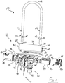
- Fig. 1 shows an exploded view of an embodiment of a two-wheel lock 10 according to the invention with alarm function.
- the two-wheel lock 10 comprises a lock body 22 and a securing bracket 12, which can be made in particular of metal.
- the securing bracket 12 of this embodiment is rigid and U-shaped and has a first end 14 and a second end 16 which can be inserted into the lock body 22.
- the securing bracket 12 on the in Fig. 1 shown front a first locking recess 18 and on the back (in Fig. 1 not visible) a second locking recess 20.
- the securing bracket 12 has a second locking recess 20 on the front and a first locking recess 18 on the rear.
- the first and the second locking recess 18, 20 can each cooperate with a locking mechanism 40 in order to lock the securing bracket 12 on the lock body 22.
- the lock body 22 comprises a tubular housing 26, which can be formed in particular from metal.
- the housing 26 has a first end 28 and a second end 30 on the longitudinal side. At the ends 28, 30, an access opening 32 is formed through which an interior 34 of the housing 26 is accessible. In an alternative embodiment, one of the access openings 32 can also be closed; in this case the housing 26 forms a cylinder open on one side. On the circumferential side, the housing 26 has close to its respective ends 28, 30 insertion openings 24.
- the ends 14, 16 of the securing bracket 12 can be guided into the interior 34 of the housing 26 through the insertion openings in order to close the two-wheel lock 10 and to lock the securing bracket 12 on the lock body 22.
- the interior 34 of the housing 26 houses the locking mechanism 40 and an alarm device 60.
- the locking mechanism 40 comprises a lock cylinder with a cylinder core 44, which can be rotated by an assigned key 42, a drive extension 46, a first bolt 50 and a second bolt 52.
- the cylinder core 44 is rotatably mounted in a cylinder housing 45.
- the locking cylinder can be designed, for example, as a plate cylinder with a plurality of plate tumblers, which enables a configuration in which the key 42 can be removed from the cylinder core 44 in two different rotational positions, in particular offset by 180 ° to one another.
- the locking cylinder is coupled via the drive extension 46 to the first bolt 50 and the second bolt 52 in order to drive the bolts 50, 52 for an unlocking movement or a locking movement.
- the drive extension 46 is arranged between the cylinder core 44 of the locking cylinder and the bolts 50, 52 and acts as a deflection device which deflects a rotary movement of the cylinder core 44 into a linear movement of the bolts 50, 52.
- the drive extension 46 has a plurality of eccentrically arranged pins 48 which can engage in corresponding guideways 54 of the first and second bolts 50, 52 in order to move them laterally when the cylinder core 44 rotates.
- the alarm device 60 comprises an acceleration sensor or vibration sensor (not shown) and a position detector 62 for determining the position of the locking mechanism 40.
- the position detector 62 can have, for example, a magnetic field sensor, a magnetic switch (e.g. a reed switch) or a contact switch.
- the position detector 62 determines, in particular, a position of a permanent magnet 64 arranged on the first latch 50.
- the measured value of the magnetic field strength is used to determine the position of the permanent magnet 64 and thus the position of the first latch 50 relative to the position detector 62.
- further permanent magnets can be provided, which can for example be connected to the second latch 52 in order to also detect the position of the second latch 52.
- embodiments are also conceivable that do without permanent magnets 64 in order to determine the position of the first bolt 50 and / or the second bolt 52 by means of the position detector 62, for example by using a contact switch.
- a contact switch can interact, for example, with an elevation on one of the bolts 50, 52 or with a cam of the drive extension 46.
- the alarm device 60 further comprises an energy source 66, for example one or more commercially available batteries and / or electrical accumulators, an evaluation and control circuit, an acoustic and / or optical signal transmitter, for example a loudspeaker and / or a light-emitting diode, and / or a radio transmitter unit for wireless transmission of an alarm signal (not shown).
- an energy source 66 for example one or more commercially available batteries and / or electrical accumulators
- an evaluation and control circuit for example acoustic and / or optical signal transmitter, for example a loudspeaker and / or a light-emitting diode, and / or a radio transmitter unit for wireless transmission of an alarm signal (not shown).
- the first end 28 and the second end 30 of the housing 26 are each closed by a first closure 70 and a second closure 72.
- the first closure 70 is a substantially semi-cylindrical carrier body.
- the carrier body is positively inserted along a cylindrical circumference into the access opening 32 of the housing 26 formed at the first end 28 of the housing 26.
- the first closure 70 has a first securing section 74 with an insertion opening 76, which in an assembled state of the first closure 70, in which the first closure 70 closes the first end 28 of the housing 26, is aligned with one of the insertion openings 24 of the housing 26.
- the first closure 70 comprises the cylinder housing 45, which forms a receptacle 78 in the carrier body, in which the cylinder core 44 is mounted.
- the alarm device 60 is essentially arranged in the second closure 72 of the housing 26.
- the second closure 72 is positively inserted into the access opening 32 of the housing 26 formed at the second end 30 of the housing 26.
- the second closure 72 is designed as an essentially cylindrical body, which removably closes the second end 30 of the housing 26 in an assembled state.
- the second closure 72 has a second securing section 80 with an insertion opening 82, which in the assembled state of the second closure 72 is aligned with one of the insertion openings 24 of the housing 26.
- the second closure 72 is non-positively locked against inadvertent loosening by at least one (in the case shown two) permanent magnets 84, which are arranged on an outside of the second closure 72 and can establish a magnetic connection with the material of the housing 26 the housing 26 secured.
- the first end 28 and the second end 30 of the housing 26 are surrounded on the outside by a respective protective cover 86.
- the protective sleeves 86 have insertion openings 88, which are aligned with the insertion openings 24 of the housing 26.
- the protective sleeves 86 can be designed as a cap and, for example, made of a flexible material, in particular plastic.
- the protective sleeves 86 are designed to be detachable, ie they can be removed from the housing 26 by pulling or pushing or pulled onto the housing 26.
- Fig. 2 shows a perspective view of the embodiment of FIG Fig. 1 , wherein the locking mechanism 40 is in an unlocked position.
- the housing 26 and the protective cover 86 have been removed to clarify the locking mechanism 40.
- the unlocked position neither the first bolt 50 nor the second bolt 52 of the locking mechanism 40 engages with the first and second locking recesses 18, 20 of the securing bracket 12.
- the securing bracket 12 is thus released for movement into the open position shown, in which it is completely released from the lock body 22 with its two ends 14, 16.
- the alarm device 60 is not activated in the unlocked position of the locking mechanism 40.
- the cylinder core 44 can be rotated by means of the key 42 either in a first direction of rotation or in an opposite second direction of rotation.
- the unlocking position thus forms a central position for the actuation of the locking cylinder in order to selectively bring the locking mechanism 40 or the locking cylinder into a different position.
- the lock cylinder or the cylinder core 44 can be brought into a first rotational position, corresponding to a first locking position, by a rotary actuation in the first direction of rotation (cf. Fig. 3 ).
- the lock cylinder or the cylinder core 44 can be brought into a second rotational position, corresponding to a second locking position, by a rotary actuation in the second direction of rotation (cf. Fig. 4 ).
- the first rotational position, the second rotational position and the third rotational position can each be offset by 90 ° to one another.
- the first rotational position of the cylinder core 44 can be offset by an angle of 90 ° with respect to the third rotational position
- the second rotational position of the cylinder core 44 with respect to the third rotational position by an angle of 90 ° and with respect to the first rotational position by an angle of 180 ° can be offset.
- the first bolt 50 and the second bolt 52 are each driven in opposite directions to one another both in the first direction of rotation and in the second direction of rotation.
- a similar, mutually opposite movement of the first and the second latch 50, 52 is provided, the user being able to select a desired locking position by means of the actuation direction.
- the opposite movement of the first and second bolts 50, 52 is brought about by the drive extension 46 of the locking cylinder, the pins 48 of which engage in the guideways 54 of the first and second bolts 50, 52 in order to laterally counteract these when the locking cylinder 44 is actuated move.
- Fig. 3 shows a perspective view of the embodiment of FIG Fig. 2 , wherein the locking mechanism 40 is in the first locking position.
- the securing bracket 12 assumes the closed position, its first end 14 engaging in the insertion opening 76 of the first closure 70 and its second end 16 engaging in the insertion opening 82 of the second closure 72.
- the first latch 50 stands with the first Locking recess 18 of the first end 14 of the securing bracket 12 engages, while the second latch 52 engages with the (rear) first locking recess 18 of the second end 16 of the securing bracket 12.
- the securing bracket is thus mechanically secured in the lock body 22 in the first locking position.
- the alarm device 60 is also not activated in the first locking position of the locking mechanism 40.
- Fig. 4 shows a perspective view of the embodiment of FIG Fig. 2 , wherein the locking mechanism 40 is, however, in the second locking position, which at the same time corresponds to an alarm activation position of the locking mechanism 40.
- the key 42 is opposite to the rotational position Fig. 3 rotated by 180 °.
- the first latch 50 engages with the second locking recess 20 of the second end 16 of the securing bracket 12, while the second latch 52 engages with the (rear) second locking recess 20 of the first end 14 of the securing bracket 12.
- a detection signal corresponding to the position of the first latch 50 is generated in the position detector 62, which can be forwarded, for example, to the evaluation and control circuit of the alarm device 60 in order to activate the alarm device 60.
- This activation of the alarm device 60 can take place immediately or with a time delay, for example in order to enable the authorized user to end a locking process.
- the securing bracket 14 is thus mechanically secured to the lock body 22 and is also protected against possible manipulation by the activated alarm device 60.
- the alarm device 60 can be transferred to a monitoring mode in which the alarm device 60 is based on the signals from the acceleration sensor or vibration sensor and For example, a comparison with a respective threshold value constantly checks whether an impermissible change in position or other movement has taken place. If applicable, the alarm device 60 outputs an acoustic and / or optical alarm signal. It can be provided that a pre-alarm signal is output first, a main alarm signal, which can be louder than the pre-alarm signal, for example, only after a main alarm delay interval has elapsed and as a result of a change in position that is still detected.
- the user can thus not only bring about a desired mechanical locking, but can also select in a simple manner whether the alarm device 60 should be activated or not.
- the locking mechanism 40 is brought into an alarm activation position by means of the assigned key 42, which is provided in addition to an unlocking position and a locking position of the locking mechanism 40.
- the key 42 can be inserted into the cylinder core 44 in three different positions of the cylinder core 44 and can be removed from the cylinder core 44, namely in the first locking position (alarm device 60 deactivated), in the second locking position (alarm activation position) and in the unlocking position.
- two different positions of the locking mechanism 40 can be selected, in which the assigned key 42 can be removed from the locking cylinder, the alarm device 60 being deactivated in one position and the alarm device 60 being activated in the other position.
- the locking mechanism 40 comprises a lock cylinder which can be actuated by an associated key 42 and has a cylinder core 44 and a drive extension 46.
- the lock cylinder could be replaced, for example, by an electric motor, which in particular has a reduction gear and an associated control device can have and can drive the drive extension 46 to a rotational movement. This can happen, for example, on the basis of a coded control signal which is transmitted by the authorized user by means of a radio remote control unit.
- the authorized user can indirectly select or control an activation state of the alarm device via the locking mechanism by moving the locking mechanism into an alarm activation position.
Abstract
Ein Schloss mit Alarmfunktion für ein Zweirad umfasst einen Schlosskörper und einen Sicherungsbügel, der relativ zu dem Schlosskörper zwischen einer Sicherungsstellung zum Sichern des Zweirads und einer Offenstellung zum Freigeben des Zweirads bewegbar ist, wobei der Schlosskörper einen Verriegelungsmechanismus aufweist, um den Sicherungsbügel in der Sicherungsstellung wahlweise an dem Schlosskörper zu verriegeln, wobei der Schlosskörper ferner eine Alarmeinrichtung zum Ausgeben eines Alarmsignals umfasst. Der Verriegelungsmechanismus ist wahlweise in eine Entriegelungsstellung, eine Verriegelungsstellung oder eine Alarmaktivierungsstellung bringbar, wobei in der Entriegelungsstellung der Sicherungsbügel für eine Bewegung in die Offenstellung freigegeben ist, wobei in der Verriegelungsstellung der in der Sicherungsstellung befindliche Sicherungsbügel an dem Schlosskörper verriegelt ist, und wobei durch Versetzen des Verriegelungsmechanismus in die Alarmaktivierungsstellung die Alarmeinrichtung aktiviert oder aktivierbar ist.A lock with an alarm function for a two-wheeler comprises a lock body and a securing bracket, which can be moved relative to the lock body between a securing position for securing the two-wheeler and an open position for releasing the two-wheeler, the lock body having a locking mechanism to selectively secure the securing bracket in the securing position to lock on the lock body, the lock body further comprising an alarm device for outputting an alarm signal. The locking mechanism can optionally be brought into an unlocking position, a locking position or an alarm activation position, the locking bracket being released for movement into the open position in the unlocking position, the locking bracket located in the locking position being locked on the lock body in the locking position, and being moved of the locking mechanism in the alarm activation position, the alarm device is activated or can be activated.
Description
Die vorliegende Erfindung betrifft ein Schloss mit Alarmfunktion für ein Zweirad, mit einem Schlosskörper und einem Sicherungsbügel, der relativ zu dem Schlosskörper zwischen einer Sicherungsstellung zum Sichern des Zweirads und einer Offenstellung zum Freigeben des Zweirads bewegbar ist, wobei der Schlosskörper einen Verriegelungsmechanismus aufweist, um den Sicherungsbügel in der Sicherungsstellung wahlweise an dem Schlosskörper zu verriegeln, wobei der Schlosskörper ferner eine Alarmeinrichtung zum Ausgeben eines Alarmsignals umfasst.The present invention relates to a lock with an alarm function for a two-wheeler, with a lock body and a securing bracket which can be moved relative to the lock body between a securing position for securing the two-wheeler and an open position for releasing the two-wheeler, the lock body having a locking mechanism to prevent the Locking the safety bracket in the locking position optionally on the lock body, the lock body further comprising an alarm device for outputting an alarm signal.
Ein derartiges Schloss kann beispielsweise als ein U-Bügel-Schloss ausgebildet sein, das einen starren, im Wesentlichen U-förmigen Sicherungsbügel besitzt, oder als ein Gelenkschloss mit einem Gelenkstab als Sicherungsbügel, der mehrere schwenkbar miteinander verbundene Gelenkstäbe aufweist. Ein Zweiradschloss der genannten Art kann auch als ein sogenanntes Rahmenschloss ausgebildet sein, bei dem ein Drehbügel oder Schwenkbügel zwischen die Speichen eines der Laufräder eines Fahrrads greift. Ferner kann ein derartiges Schloss beispielsweise als ein Bremsscheibenschloss ausgebildet sein, bei dem der Sicherungsbügel in eine Belüftungsöffnung einer Bremsscheibe eines Motorrads oder eines Motorrollers eingreift. Der Sicherungsbügel kann auch flexibel sein, beispielsweise in Form einer Kette oder eines Drahtseils, die bzw. das wahlweise an dem Schlosskörper verriegelt werden kann.Such a lock can be designed, for example, as a U-bracket lock, which has a rigid, essentially U-shaped securing bracket, or as an articulated lock with an articulated rod as a securing bracket, which has a plurality of pivoting rods which are pivotally connected to one another. A two-wheel lock of the type mentioned can also be designed as a so-called frame lock, in which a rotating bracket or swivel bracket engages between the spokes of one of the wheels of a bicycle. Furthermore, such a lock can be designed, for example, as a brake disc lock, in which the securing bracket engages in a ventilation opening of a brake disc of a motorcycle or a motor scooter. The securing bracket can also be flexible, for example in the form of a chain or a wire rope, which can optionally be locked on the lock body.
Ein Schloss der genannten Art dient beispielsweise zum Sichern eines Zweirads an einem Fahrradständer, einem Laternenpfosten oder einem sonstigen stationären Objekt, oder zum Sichern eines Zweirads gegen ein unbefugtes Wegfahren.A lock of the type mentioned is used, for example, to secure a two-wheeler to a bicycle stand, a lamppost or another stationary object, or to secure a two-wheeler against unauthorized driving away.
Wenn der Sicherungsbügel entriegelt ist, kann der Sicherungsbügel in eine Offenstellung gebracht werden, in der der Sicherungsbügel mit einem Ende oder vollständig von dem Schlosskörper gelöst ist. Ausgehend von der Offenstellung kann der Sicherungsbügel beispielsweise um einen Rahmenabschnitt des Zweirads und einen Fahrradständer, Laternenpfosten oder dergleichen geführt werden, oder der Sicherungsbügel wird lediglich durch ein bewegliches Teil (z.B. Felge, Bremsscheibe) des Zweirads geführt. Der Sicherungsbügel kann sodann (vollständig) geschlossen und an dem Schlosskörper verriegelt werden, um somit das Zweirad gegen eine unbefugte Entnahme bzw. ein unbefugtes Wegfahren zu sichern. Das Entriegeln des Sicherungsbügels kann dadurch erfolgen, dass der befugte Benutzer den Verriegelungsmechanismus des Schlosses mittels eines zugeordneten Schlüssels oder eines sonstigen Identmittels (z.B. Transponder) betätigt.When the securing bracket is unlocked, the securing bracket can be brought into an open position in which the securing bracket is released from the lock body at one end or completely. Starting from the open position, the securing bracket can be guided, for example, around a frame section of the two-wheeler and a bicycle stand, lamppost or the like, or the securing bracket is only guided through a movable part (e.g. rim, brake disc) of the two-wheeler. The safety bracket can then be (completely) closed and locked on the lock body, in order to secure the two-wheeler against unauthorized removal or unauthorized driving away. The safety bracket can be unlocked by the authorized user actuating the locking mechanism of the lock by means of an assigned key or other identification means (e.g. transponder).
Im Falle eines Manipulationsversuchs an einem Schloss der genannten Art, um ein hierdurch gesichertes Zweirad zu entwenden, ist die benötigte Zeit zum unbefugten Öffnen des Schlosses ein wichtiger Aspekt. Je weniger Zeit einem Dieb zur Verfügung steht, umso schwieriger gestaltet sich der erfolgreiche Manipulationsversuch. Es ist daher denkbar, das Schloss mit einer Alarmeinrichtung auszustatten, die ein akustisches und/oder optisches Alarmsignal ausgibt, sobald ein Manipulationsversuch detektiert wird, beispielsweise durch Feststellen einer Lageänderung oder Erschütterung während eines Überwachungsbetriebs. In der Praxis gestaltet sich jedoch eine komfortable Bedienung einer solchen Alarmeinrichtung durch den befugten Benutzer als schwierig, insbesondere was das Scharfschalten der Alarmeinrichtung betrifft (nachfolgend als "Aktivieren" der Alarmeinrichtung bezeichnet). Eine beispielsweise auf Erschütterung sensible Alarmeinrichtung darf nicht während des Transports des Schlosses die Ausgabe eines Alarmsignals auslösen, und nicht bei jedem Absperren des Zweirads ist auch eine Aktivierung der Alarmeinrichtung erwünscht (z.B. Sichern des Zweirads an einem Fahrradträger eines Kraftfahrzeugs).In the event of a manipulation attempt on a lock of the type mentioned in order to steal a two-wheeler secured thereby, the time required for unauthorized opening of the lock is an important aspect. The less time a thief has, the more difficult it is to attempt manipulation. It is therefore conceivable to equip the lock with an alarm device which emits an acoustic and / or visual alarm signal as soon as a manipulation attempt is detected, for example by detecting a change in position or vibration during a monitoring operation. In practice, however, convenient operation of such an alarm device by the authorized user is difficult, in particular with regard to arming the alarm device (hereinafter referred to as "activating" the alarm device). An alarm device that is sensitive to vibrations, for example, must not trigger the output of an alarm signal during the transport of the lock, and activation of the alarm device is not desirable each time the bicycle is locked (e.g. securing the bicycle to a bicycle rack of a motor vehicle).
Es ist deshalb eine Aufgabe der Erfindung, ein Zweiradschloss mit Alarmfunktion anzugeben, das eine komfortable und zuverlässige Bedienung der Alarmeinrichtung ermöglicht.It is therefore an object of the invention to provide a two-wheel lock with an alarm function which enables convenient and reliable operation of the alarm device.
Diese Aufgabe wird durch ein Zweiradschloss mit Alarmfunktion mit den Merkmalen des Anspruchs 1 gelöst, und insbesondere dadurch, dass der Verriegelungsmechanismus wahlweise in eine Entriegelungsstellung, eine Verriegelungsstellung oder eine Alarmaktivierungsstellung bringbar ist, wobei in der Entriegelungsstellung der Sicherungsbügel für eine Bewegung in die Offenstellung freigegeben ist, wobei in der Verriegelungsstellung der in der Sicherungsstellung befindliche Sicherungsbügel an dem Schlosskörper verriegelt ist, und wobei durch Versetzen des Verriegelungsmechanismus in die Alarmaktivierungsstellung die Alarmeinrichtung aktiviert oder aktivierbar ist.This object is achieved by a two-wheel lock with an alarm function with the features of
Der Verriegelungsmechanismus kann zusätzlich zu seiner Entriegelungsstellung und seiner Verriegelungsstellung auch - zumindest temporär - in eine Alarmaktivierungsstellung gebracht werden. Die Alarmeinrichtung des Zweiradschlosses kann aktiviert sein, solange der Verriegelungsmechanismus sich in der Alarmaktivierungsstellung befindet. Es kann auch vorgesehen sein, dass durch temporäres Versetzen des Verriegelungsmechanismus in die Alarmaktivierungsstellung die Alarmeinrichtung aktiviert wird, wobei die Alarmeinrichtung aktiviert bleiben kann, selbst wenn der Verriegelungsmechanismus sogleich in eine andere Stellung gebracht wird. Die Alarmaktivierungsstellung kann hinsichtlich des Verriegelungsmechanismus eine weitere (d.h. zweite) Verriegelungsstellung bilden, wie nachstehend noch erläutert wird.In addition to its unlocked position and its locked position, the locking mechanism can also - at least temporarily - be brought into an alarm activation position. The alarm device of the two-wheel lock can be activated as long as the locking mechanism is in the alarm activation position. Provision can also be made for the alarm device to be activated by temporarily moving the locking mechanism into the alarm activation position, the alarm device being able to remain activated even if the locking mechanism is immediately moved to another position. The alarm activation position can form a further (i.e. second) locking position with regard to the locking mechanism, as will be explained below.
Jedenfalls kann ausgenutzt werden, dass ohnehin eine Betätigung des Verriegelungsmechanismus des Zweiradschlosses durch den befugten Benutzer vorgesehen ist, insbesondere für ein Entriegeln oder Verriegeln, zum Beispiel mittels eines zugeordneten Schlüssels, mittels eines elektronischen Identmittels, durch Übermittlung eines Kodes oder durch eine Kombination hiervon. Durch eine geeignete Betätigung des Verriegelungsmechanismus, nämlich durch das Versetzen des Verriegelungsmechanismus in eine Alarmaktivierungsstellung, kann der befugte Benutzer nicht nur den Verriegelungszustand oder Entriegelungszustand des Verriegelungsmechanismus auswählen, sondern auch festlegen, ob die Alarmeinrichtung aktiviert werden bzw. aktiviert sein soll, oder nicht. Die Alarmaktivierungsstellung kann hierbei indirekt (beispielsweise aus einem Steuersignal für den Verriegelungsmechanismus) oder unmittelbar (beispielsweise durch einen Stellungsdetektor) ermittelt werden. Hierdurch ergibt sich eine komfortable und insbesondere auch fehlersichere Bedienung des Zweiradschlosses und insbesondere der Alarmeinrichtung.In any case, use can be made of the fact that actuation of the locking mechanism of the two-wheel lock by the authorized user is provided in any case, in particular for unlocking or locking, for example by means of an assigned key, by means of an electronic identification means, by transmission a code or a combination thereof. By a suitable actuation of the locking mechanism, namely by placing the locking mechanism in an alarm activation position, the authorized user can not only select the locking state or unlocking state of the locking mechanism, but also determine whether or not the alarm device should be activated or activated. The alarm activation position can be determined indirectly (for example from a control signal for the locking mechanism) or directly (for example by a position detector). This results in a comfortable and, in particular, also fail-safe operation of the two-wheel lock and in particular the alarm device.
Vorteilhafte Ausführungsformen der Erfindung sind den abhängigen Ansprüchen, der Beschreibung und der Zeichnung zu entnehmen.Advantageous embodiments of the invention can be found in the dependent claims, the description and the drawing.
Bei einigen Ausführungsformen kann das Zweiradschloss dazu ausgebildet sein, dass durch Versetzen des Verriegelungsmechanismus in die Alarmaktivierungsstellung die Alarmeinrichtung automatisch aktiviert wird.In some embodiments, the two-wheel lock can be configured such that the alarm device is automatically activated by moving the locking mechanism into the alarm activation position.
Bei einigen Ausführungsformen ist der Verriegelungsmechanismus rein mechanisch ausgebildet.In some embodiments, the locking mechanism is designed to be purely mechanical.
Insbesondere kann der Verriegelungsmechanismus einen Schließzylinder aufweisen, der mittels eines Schlüssels drehbetätigbar ist. Der Schließzylinder kann direkt oder indirekt mit einem oder mehreren Riegel(n) gekoppelt sein, um in der Entriegelungsstellung der Sicherungsbügel freizugeben und in der Verriegelungsstellung den Sicherungsbügel (sofern dieser sich in der Sicherungsstellung befindet) an dem Schlosskörper zu verriegeln. Bei einigen Ausführungsformen kann durch Drehbetätigung des Schließzylinders mittels des Schlüssels die Alarmeinrichtung direkt oder indirekt aktiviert werden, indem der Schließzylinder in eine Alarmaktivierungsstellung gebracht wird, die sich von der Entriegelungsstellung und der Verriegelungsstellung oder einer ersten Verriegelungsstellung unterscheidet.In particular, the locking mechanism can have a locking cylinder which can be rotated by means of a key. The locking cylinder can be directly or indirectly coupled to one or more bolts to release the locking bracket in the unlocked position and to lock the locking bracket (if it is in the locking position) to the lock body in the locking position. In some embodiments, by turning the lock cylinder by means of the key, the alarm device can be activated directly or indirectly by turning the lock cylinder into a Alarm activation position is brought, which differs from the unlocking position and the locking position or a first locking position.
Der Schließzylinder kann bei einigen Ausführungsformen ein Zylindergehäuse und einen in dem Zylindergehäuse drehbar gelagerten Zylinderkern aufweisen, wobei die Verriegelungsstellung des Verriegelungsmechanismus einer ersten Drehstellung des Zylinderkerns entspricht, wobei die Alarmaktivierungsstellung des Verriegelungsmechanismus einer zweiten Drehstellung des Zylinderkerns entspricht, und die Entriegelungsstellung des Verriegelungsmechanismus einer dritten Drehstellung des Zylinderkerns entspricht. Hierdurch kann der Benutzer die verschiedenen Stellungen bzw. Zustände des Verriegelungsmechanismus leicht voneinander unterscheiden und ohne Fehlbedienung auswählen.In some embodiments, the locking cylinder can have a cylinder housing and a cylinder core rotatably mounted in the cylinder housing, the locking position of the locking mechanism corresponding to a first rotational position of the cylinder core, the alarm activation position of the locking mechanism corresponding to a second rotational position of the cylinder core, and the unlocking position of the locking mechanism of a third rotational position corresponds to the cylinder core. As a result, the user can easily differentiate the different positions or states of the locking mechanism from one another and select them without incorrect operation.
Bei einigen Ausführungsformen kann vorgesehen sein, dass der Schließzylinder ausgehend von der Entriegelungsstellung in eine erste Drehrichtung oder in eine hierzu entgegengesetzte zweite Drehrichtung betätigbar ist. Somit bildet die Entriegelungsstellung eine Mittelstellung für die Betätigung des Schließzylinders, um den Verriegelungsmechanismus bzw. den Schließzylinder wahlweise in eine andere Stellung zu bringen. Bei anderen Ausführungsformen kann vorgesehen sein, dass der Schließzylinder ausgehend von der Verriegelungsstellung in eine erste Drehrichtung oder in eine hierzu entgegengesetzte zweite Drehrichtung betätigbar ist. Somit bildet die Verriegelungsstellung eine Mittelstellung für die Betätigung des Schließzylinders.In some embodiments, it can be provided that the locking cylinder can be actuated from the unlocking position in a first direction of rotation or in a second direction of rotation opposite thereto. The unlocking position thus forms a central position for the actuation of the locking cylinder in order to bring the locking mechanism or the locking cylinder optionally into another position. In other embodiments, it can be provided that the locking cylinder can be actuated from the locking position in a first direction of rotation or in a second direction of rotation opposite thereto. The locking position thus forms a central position for the actuation of the locking cylinder.
Bei einigen Ausführungsformen können die erste Drehstellung, die zweite Drehstellung und die dritte Drehstellung des Zylinderkerns um jeweils 90° zueinander versetzt sein. Hierdurch ergibt sich für den Benutzer eine klare, gut ersichtliche Unterscheidung der verschiedenen Drehstellungen, um den Verriegelungsmechanismus fehlerfrei bedienen zu können. Beispielsweise kann die erste Drehstellung des Zylinderkerns bezüglich der dritten Drehstellung des Zylinderkerns um einen Winkel von 90° versetzt sein, wobei die zweite Drehstellung des Zylinderkerns bezüglich der dritten Drehstellung des Zylinderkerns um einen Winkel von 90° und bezüglich der ersten Drehstellung des Zylinderkerns um einen Winkel von 180° versetzt ist.In some embodiments, the first rotational position, the second rotational position and the third rotational position of the cylinder core can each be offset by 90 ° to one another. This provides the user with a clear, clearly visible distinction between the different rotational positions in order to be able to operate the locking mechanism without errors. For example, the first rotational position of the cylinder core with respect to the third rotational position of the cylinder core by an angle of 90 °, the second rotational position of the cylinder core with respect to the third rotational position of the cylinder core by an angle of 90 ° and with respect to the first rotational position of the cylinder core by an angle of 180 ° ,
Bei einigen Ausführungsformen kann der Schlüssel in zwei verschiedenen Stellungen des Zylinderkerns in den Zylinderkern einführbar und aus dem Zylinderkern entnehmbar sein. Hierdurch können zwei verschiedene Stellungen des Verriegelungsmechanismus ausgewählt werden, in denen der zugeordnete Schlüssel aus dem Schließzylinder entfernt werden kann. Bei diesen zwei verschiedenen Stellungen kann es sich insbesondere um zwei Verriegelungsstellungen handeln, um jeweils den Sicherungsbügel an dem Schlosskörper zu verriegeln (bei aktivierter Alarmeinrichtung bzw. deaktivierter Alarmeinrichtung). Beispielsweise kann vorgesehen sein, dass sowohl in der ersten Drehstellung des Zylinderkerns als auch in der zweiten Drehstellung des Zylinderkerns der zugeordnete Schlüssel in den Zylinderkern einführbar und aus dem Zylinderkern entnehmbar ist.In some embodiments, the key can be inserted into the cylinder core in two different positions of the cylinder core and can be removed from the cylinder core. As a result, two different positions of the locking mechanism can be selected, in which the assigned key can be removed from the locking cylinder. These two different positions can in particular be two locking positions in order to lock the safety bracket on the lock body (when the alarm device is activated or the alarm device is deactivated). For example, it can be provided that the assigned key can be inserted into the cylinder core and removed from the cylinder core both in the first rotational position of the cylinder core and in the second rotational position of the cylinder core.
Bei einigen Ausführungsformen kann der Schließzylinder mehrere Zuhaltungen aufweisen, die durch Einführen des Schlüssels in den Zylinderkern versetzt werden. Durch die mehreren Zuhaltungen kann ein spezifisches Schließgeheimnis des jeweiligen Schließzylinders kodiert sein.In some embodiments, the lock cylinder can have a plurality of tumblers which are displaced by inserting the key into the cylinder core. A specific locking secret of the respective locking cylinder can be encoded by the multiple tumblers.
Insbesondere kann der Schließzylinder als ein Plättchenzylinder mit mehreren Plättchenzuhaltungen ausgebildet sein, wie dies generell beispielsweise aus
Was die mechanische Verriegelung des Sicherungsbügels an dem Schlosskörper betrifft, kann bei einigen Ausführungsformen der Verriegelungsmechanismus einen oder mehrere Riegel aufweisen, der bzw. die den Sicherungsbügel, sofern dieser sich in der Sicherungsstellung befindet, an dem Schlosskörper verriegelt/verriegeln. Insbesondere kann der Verriegelungsmechanismus wenigstens einen Riegel aufweisen, der mittels des zugeordneten Schlüssels (insbesondere über einen Schließzylinder) antreibbar ist und in der Verriegelungsstellung des Verriegelungsmechanismus mit dem Sicherungsbügel in Eingriff steht, um den Sicherungsbügel an dem Schlosskörper zu verriegeln.With regard to the mechanical locking of the securing bracket on the lock body, in some embodiments the locking mechanism can have one or more bolts which lock the locking bracket, if this is in the securing position, on the lock body. In particular, the locking mechanism can have at least one bolt which can be driven by means of the associated key (in particular via a locking cylinder) and which engages with the securing bracket in the locking position of the locking mechanism in order to lock the securing bracket on the lock body.
Bei einigen Ausführungsformen kann der Riegel oder ein weiterer Riegel, der mittels des Schließzylinders antreibbar ist, in der Alarmaktivierungsstellung des Verriegelungsmechanismus mit dem Sicherungsbügel in Eingriff stehen. Die Alarmaktivierungsstellung kann hierbei eine weitere Verriegelungsstellung des Verriegelungsmechanismus bilden.In some embodiments, the bolt or another bolt that is drivable by means of the locking cylinder can engage the securing bracket in the alarm activation position of the locking mechanism. The alarm activation position can form a further locking position of the locking mechanism.
Bei einigen Ausführungsformen kann der Sicherungsbügel wenigstens eine Verriegelungsvertiefung aufweisen, wobei ein Riegel in die Verriegelungsvertiefung eingreift, wenn der Verriegelungsmechanismus sich in der Verriegelungsstellung (oder einer weiteren Verriegelungsstellung) befindet. In der Entriegelungsstellung des Verriegelungsmechanismus greift der jeweilige Riegel hingegen nicht in die zugeordnete(n) Verriegelungsvertiefung(en) des Sicherungsbügels. Die jeweilige Verriegelungsvertiefung kann beispielsweise als Nut oder als Bohrung ausgebildet sein.In some embodiments, the securing bracket may have at least one locking recess, with a latch engaging the locking recess when the locking mechanism is in the locking position (or another locking position). In the unlocked position of the locking mechanism, however, the respective latch does not engage in the associated locking recess (s) in the securing bracket. The respective locking recess can be designed, for example, as a groove or as a bore.
Bei einigen Ausführungsformen kann der Schließzylinder mit dem wenigstens einen Riegel über eine Umlenkeinrichtung gekoppelt sein, die eine Drehbewegung des Schließzylinders in eine lineare Bewegung des Riegels umlenkt. Die Umlenkeinrichtungen kann wenigstens einen exzentrischen Fortsatz (z.B. Zapfen), eine sonstige Art von Nocken, oder eine Rampe aufweisen, wobei ein zugeordnetes Gegenelement vorgesehen sein kann (z.B. Führungsbahn, Kulisse oder Gegenrampe). Ein Element der Umlenkeinrichtung kann dem Schließzylinder zugeordnet sein und ein weiteres Element der Umlenkeinrichtung kann dem jeweiligen Riegel zugeordnet sein. Die lineare Bewegung des Riegels kann bezüglich der Drehachse des Schließzylinders eine seitliche, insbesondere radiale, Bewegung sein, oder eine axiale Bewegung, insbesondere koaxial oder parallel versetzt zu der Drehachse des Schließzylinders.In some embodiments, the locking cylinder can be coupled to the at least one bolt via a deflection device which deflects a rotary movement of the locking cylinder into a linear movement of the bolt. The deflection devices can have at least one eccentric extension (eg pin), another type of cam, or a ramp, an associated one Counter element can be provided (eg guideway, backdrop or counter ramp). One element of the deflection device can be assigned to the locking cylinder and another element of the deflection device can be assigned to the respective bolt. The linear movement of the bolt can be a lateral, in particular radial, movement with respect to the axis of rotation of the locking cylinder, or an axial movement, in particular offset coaxially or parallel to the axis of rotation of the locking cylinder.
Bei anderen Ausführungsformen kann allerdings auch eine Drehbewegung oder Schwenkbewegung des jeweiligen Riegels vorgesehen sein, wobei der Schließzylinder mit dem wenigstens einen Riegel direkt oder indirekt, insbesondere über eine Umlenkeinrichtung, gekoppelt sein kann.In other embodiments, however, a rotary movement or pivoting movement of the respective bolt can also be provided, the locking cylinder being able to be coupled to the at least one bolt directly or indirectly, in particular via a deflection device.
Alternativ zu einer rein mechanischen Ausgestaltung kann der Verriegelungsmechanismus bei einigen Ausführungsformen elektromechanisch ausgebildet sein.As an alternative to a purely mechanical configuration, the locking mechanism can be designed electromechanically in some embodiments.
Insbesondere kann der Verriegelungsmechanismus einen Elektromotor aufweisen, der als ein Stellmotor dient, insbesondere um wenigstens einen Riegel des Verriegelungsmechanismus anzutreiben. Ein derartiger Elektromotor kann direkt oder indirekt mit einem oder mehreren Riegel(n) gekoppelt sein, um in der Entriegelungsstellung den Sicherungsbügel freizugeben und in der Verriegelungsstellung den Sicherungsbügel (sofern dieser sich in der Sicherungsstellung befindet) an dem Schlosskörper zu verriegeln. Bei einigen Ausführungsformen kann durch eine Drehbewegung des Elektromotors die Alarmeinrichtung direkt oder indirekt aktiviert werden, indem der Elektromotor oder ein nachgeordnetes Antriebselement in eine Alarmaktivierungsstellung gebracht wird, die sich von der Entriegelungsstellung und der Verriegelungsstellung oder einer ersten Verriegelungsstellung unterscheidet.In particular, the locking mechanism can have an electric motor that serves as a servomotor, in particular to drive at least one bolt of the locking mechanism. Such an electric motor can be directly or indirectly coupled to one or more bolts to release the locking bracket in the unlocking position and to lock the locking bracket (if it is in the locking position) to the lock body in the locking position. In some embodiments, by rotating the electric motor, the alarm device can be activated directly or indirectly by bringing the electric motor or a downstream drive element into an alarm activation position that differs from the unlocked position and the locked position or a first locked position.
Auch bei einer elektromechanischen Ausgestaltung kann der Verriegelungsmechanismus also wenigstens einen Riegel aufweisen, der elektrisch zu einer Verriegelungsbewegung und/oder einer Entriegelungsbewegung antreibbar ist und der in der Verriegelungsstellung des Verriegelungsmechanismus mit dem Sicherungsbügel in Eingriff steht, um den Sicherungsbügel an dem Schlosskörper zu verriegeln.Even in the case of an electromechanical configuration, the locking mechanism can therefore have at least one bolt which can be driven electrically for a locking movement and / or an unlocking movement and which, in the locking position of the locking mechanism, engages with the securing bracket in order to lock the securing bracket on the lock body.
Die Betätigung eines elektromechanischen Verriegelungsmechanismus durch den befugten Benutzer kann beispielsweise durch ein elektronisches Identmittel (z.B. Transponder), durch Übermittlung eines Kodes (z.B. per Funk, insbesondere über ein mobiles Endgerät), durch Betätigung eines an dem Zweiradschloss vorgesehenen Schalters oder durch eine Kombination hiervon erfolgen.The authorized user can actuate an electromechanical locking mechanism, for example, by means of an electronic identification means (e.g. transponder), by transmitting a code (e.g. by radio, in particular via a mobile terminal), by actuating a switch provided on the two-wheel lock or by a combination thereof ,
Alternativ zu einem Elektromotor kann ein elektromechanischer Verriegelungsmechanismus beispielsweise eine elektromagnetische Antriebseinrichtung aufweisen.As an alternative to an electric motor, an electromechanical locking mechanism can have, for example, an electromagnetic drive device.
Bei einigen Ausführungsformen kann die Alarmaktivierungsstellung des Verriegelungsmechanismus, wie bereits erwähnt, eine weitere Verriegelungsstellung bilden, d.h. sowohl in der Verriegelungsstellung als auch in der Alarmaktivierungsstellung kann der Sicherungsbügel, soweit dieser sich in der Sicherungsstellung befindet, an dem Schlosskörper verriegelt werden. Bei diesen Ausführungsformen kann in der einen Verriegelungsstellung die Alarmeinrichtung deaktiviert sein, wobei in der anderen Verriegelungsstellung die Alarmeinrichtung aktiviert ist. Somit kann der Benutzer zusätzlich zu der Entriegelungsstellung, in der die Alarmeinrichtung deaktiviert sein kann, eine von zwei verschiedenen Verriegelungsstellungen auswählen, in denen der Sicherungsbügel zwar gleichermaßen mechanisch verriegelt ist (insbesondere rein mechanisch oder elektromechanisch), die Alarmeinrichtung jedoch entweder aktiviert oder deaktiviert ist.In some embodiments, as already mentioned, the alarm activation position of the locking mechanism can form a further locking position, ie both in the locking position and in the alarm activation position, the securing bracket, insofar as it is in the securing position, can be locked on the lock body. In these embodiments, the alarm device can be deactivated in one locking position, the alarm device being activated in the other locking position. Thus, in addition to the unlocking position, in which the alarm device can be deactivated, the user can select one of two different locking positions in which the safety bracket is equally mechanically locked (in particular purely mechanical or electromechanical), but the alarm device is either activated or deactivated.
Eine derartige Ausgestaltung eignet sich insbesondere für ein Zweiradschloss mit einem sogenannten Schließzwang, bei dem der Verriegelungsmechanismus zwingend in eine Verriegelungsstellung gebracht werden muss, um einen zugeordneten Schlüssel entfernen zu können. Durch Betätigung des Verriegelungsmechanismus mittels des zugeordneten Schlüssels zum Zwecke des Verriegelns des Sicherungsbügels kann der Benutzer somit nicht nur eine erwünschte mechanische Verriegelung herbeiführen, sondern auf einfache Weise zugleich auswählen, ob die Alarmeinrichtung aktiviert sein soll oder nicht.Such an embodiment is particularly suitable for a two-wheel lock with a so-called forced locking, in which the locking mechanism must be brought into a locking position in order to be able to remove an assigned key. By actuating the locking mechanism by means of the assigned key for the purpose of locking the securing bracket, the user can thus not only bring about a desired mechanical locking, but can also select in a simple manner whether the alarm device should be activated or not.
Bei einigen Ausführungsformen kann der Sicherungsbügel wenigstens eine erste Verriegelungsvertiefung und wenigstens eine zweite Verriegelungsvertiefung aufweisen, wobei der Sicherungsbügel in der Verriegelungsstellung des Verriegelungsmechanismus an der ersten Verriegelungsvertiefung verriegelt ist, und wobei der Sicherungsbügel in der weiteren Verriegelungsstellung des Verriegelungsmechanismus an der zweiten Verriegelungsvertiefung verriegelt ist. Hierdurch ist es möglich, dass der Verriegelungsmechanismus verschiedene Verriegelungsstellungen einnehmen kann (beispielsweise verschiedene Drehstellungen eines Schließzylinders, eines Elektromotors oder eines nachgeordneten Antriebselements), in denen ein Verriegeln des Sicherungsbügels erfolgt, wobei durch die verschiedenen Verriegelungsstellungen unterschiedliche Zustände der Alarmeinrichtung eingestellt sein können bzw. ausgewählt werden können.In some embodiments, the securing bracket may have at least a first locking recess and at least a second locking recess, the securing bracket being locked to the first locking recess in the locking position of the locking mechanism, and the locking bracket being locked to the second locking recess in the further locking position of the locking mechanism. This makes it possible for the locking mechanism to be able to assume different locking positions (for example, different rotational positions of a locking cylinder, an electric motor or a downstream drive element) in which the locking bracket is locked, whereby different states of the alarm device can be set or selected by the different locking positions can be.
Bei einigen Ausführungsformen kann der Verriegelungsmechanismus zwei Riegel aufweisen, wobei in der Verriegelungsstellung des Verriegelungsmechanismus der eine der zwei Riegel in die erste Verriegelungsvertiefung des Sicherungsbügels eingreift, und wobei in der weiteren Verriegelungsstellung des Verriegelungsmechanismus der andere der zwei Riegel in die zweite Verriegelungsvertiefung des Sicherungsbügels eingreift.In some embodiments, the locking mechanism can have two bolts, wherein in the locking position of the locking mechanism one of the two bolts engages in the first locking recess of the securing bracket, and in the further locking position of the locking mechanism the other of the two locking bolts engages in the second locking recess of the securing bracket.
Bei derartigen Ausführungsformen mit zwei Riegeln kann insbesondere vorgesehen sein, dass bei einer Betätigung des Verriegelungsmechanismus in einer ersten Drehrichtung die zwei Riegel gegenläufig zueinander angetrieben werden, wobei auch bei einer Betätigung des Verriegelungsmechanismus in einer zu der ersten Drehrichtung entgegengesetzten Drehrichtung die zwei Riegel gegenläufig zueinander angetrieben werden. Somit ist trotz einer unterschiedlichen Betätigungsrichtung des Verriegelungsmechanismus eine gleichartige (nämlich zueinander gegenläufige) Bewegung der Riegel vorgesehen, wobei durch die Betätigungsrichtung ein erwünschter Zustand der Alarmeinrichtung ausgewählt werden kann.In such embodiments with two bolts, it can in particular be provided that when the locking mechanism is actuated in a first direction of rotation, the two bolts are driven in opposite directions to one another, and when the locking mechanism is actuated in a direction of rotation opposite to the first direction of rotation, the two bolts are driven in opposite directions to one another become. In spite of a different actuation direction of the locking mechanism, a similar (namely opposite movement) of the bolts is provided, whereby a desired state of the alarm device can be selected by the actuation direction.
Insbesondere kann bei einigen Ausführungsformen vorgesehen sein, dass der Sicherungsbügel ein erstes Bügelende und ein zweites Bügelende aufweist, von denen jedes eine erste Verriegelungsvertiefung und eine zweite Verriegelungsvertiefung aufweist, wobei in der Verriegelungsstellung des Verriegelungsmechanismus der eine der zwei Riegel in die erste Verriegelungsvertiefung des ersten Bügelendes eingreift und der andere der zwei Riegel in die erste Verriegelungsvertiefung des zweiten Bügelendes eingreift, und wobei in der weiteren Verriegelungsstellung des Verriegelungsmechanismus der eine der zwei Riegel in die zweite Verriegelungsvertiefung des zweiten Bügelendes eingreift und der andere der zwei Riegel in die zweite Verriegelungsvertiefung des ersten Bügelendes eingreift.In particular, it can be provided in some embodiments that the securing bracket has a first bracket end and a second bracket end, each of which has a first locking recess and a second locking recess, wherein in the locking position of the locking mechanism, the one of the two bolts in the first locking recess of the first bracket end engages and the other of the two latches engages in the first locking recess of the second bracket end, and wherein in the further locking position of the locking mechanism one of the two latches engages in the second locking recess of the second bracket end and the other of the two latches in the second locking recess of the first bracket end intervenes.
Es ist allerdings nicht zwingend erforderlich, dass der Verriegelungsmechanismus zwei Riegel aufweist. Bei einigen Ausführungsformen kann der Verriegelungsmechanismus lediglich einen einzigen Riegel aufweisen, der ausgehend von der Entriegelungsstellung des Verriegelungsmechanismus unabhängig von der Richtung einer Verriegelungsbetätigung des Verriegelungsmechanismus (insbesondere unabhängig von der Richtung einer Drehbetätigung eines Schließzylinders oder Elektromotors) in dieselbe Richtung bewegt wird. Insbesondere kann vorgesehen sein, dass ausgehend von der Entriegelungsstellung des Verriegelungsmechanismus eine Betätigung in zwei verschiedene Richtungen erfolgen kann, um den Verriegelungsmechanismus in eine jeweilige Verriegelungsstellung zu versetzen, beispielsweise eine Drehbetätigung mittels des zugeordneten Schlüssels in zwei verschiedene Drehrichtungen. Hierbei können die zwei verschiedenen Betätigungsrichtungen dieselbe Verriegelungsbewegungsrichtung des Riegels bewirken. Hierfür kann vorgesehen sein, dass der Verriegelungsmechanismus eine Umlenkeinrichtung (insbesondere die bereits genannte Umlenkeinrichtung) mit zueinander symmetrischen Antriebsabschnitten aufweist, die den Riegel unabhängig von einer Betätigungsrichtung des Verriegelungsmechanismus in dieselbe Richtung antreiben. Beispielsweise kann eine solche Umlenkeinrichtung zwei zueinander symmetrische Rampen aufweisen, durch die der Riegel angetrieben wird. Gleichwohl können zwei verschiedene Betätigungsrichtungen des Verriegelungsmechanismus hinsichtlich einer Steuerung der Alarmeinrichtung voneinander unterschieden werden, beispielsweise indem lediglich in einer von zwei möglichen Betätigungsrichtungen ein entsprechender Stellungsdetektor (zum Beispiel Sensor oder Schalter) angesprochen wird (zum Beispiel über einen Permanentmagneten oder eine Erhebung).However, it is not absolutely necessary for the locking mechanism to have two bolts. In some embodiments, the locking mechanism can have only a single latch, which, starting from the unlocked position of the locking mechanism, is moved in the same direction regardless of the direction of a locking actuation of the locking mechanism (in particular regardless of the direction of a rotary actuation of a lock cylinder or electric motor). In particular, it can be provided that starting from the unlocked position of the locking mechanism an actuation can take place in two different directions in order to move the locking mechanism into a respective locking position, for example a rotary actuation in two different directions of rotation by means of the assigned key. Here, the two different actuation directions can effect the same locking movement direction of the bolt. For this purpose it can be provided that the locking mechanism has a deflection device (in particular the already mentioned deflection device) with mutually symmetrical drive sections which drive the bolt in the same direction regardless of an actuation direction of the locking mechanism. For example, such a deflection device can have two ramps which are symmetrical to one another and through which the bolt is driven. Nevertheless, two different actuation directions of the locking mechanism can be distinguished from one another with regard to controlling the alarm device, for example by only addressing a corresponding position detector (for example sensor or switch) in one of two possible actuation directions (for example via a permanent magnet or an elevation).
Bei einigen Ausführungsformen kann die Alarmeinrichtung durch mehrmaliges Versetzen des Verriegelungsmechanismus in die Alarmaktivierungsstellung abwechselnd aktivierbar und deaktivierbar sein. Hierdurch kann durch ein temporäres Versetzen des Verriegelungsmechanismus in die Alarmaktivierungsstellung ein erwünschter Zustand der Alarmeinrichtung ausgewählt werden, ohne dass der Verriegelungsmechanismus in der Alarmaktivierungsstellung verbleiben muss. Insbesondere kann durch ein jeweiliges Versetzen des Verriegelungsmechanismus in die Alarmaktivierungsstellung ein Umschalten zwischen einem aktivierten Zustand der Alarmeinrichtung und einem deaktivierten Zustand der Alarmeinrichtung bewirkt werden. Hierdurch ist es beispielsweise möglich, dass zwei Stellungen des Verriegelungsmechanismus (Verriegelungsstellung und Entriegelungsstellung) ausschließlich für die mechanische Verriegelungsfunktion vorgesehen sind, und dass eine weitere Stellung (Alarmaktivierungsstellung) ausschließlich für das Aktivieren der Alarmeinrichtung vorgesehen ist.In some embodiments, the alarm device can be activated and deactivated alternately by repeatedly moving the locking mechanism into the alarm activation position. As a result, a desired state of the alarm device can be selected by temporarily moving the locking mechanism into the alarm activation position without the locking mechanism having to remain in the alarm activation position. In particular, a switch between an activated state of the alarm device and a deactivated state of the alarm device can be effected by a respective movement of the locking mechanism into the alarm activation position. This makes it possible, for example, for two positions of the locking mechanism (locking position and unlocking position) to be provided exclusively for the mechanical locking function and that a further position (alarm activation position) is provided exclusively for activating the alarm device.
Eine derartige Ausgestaltung eignet sich insbesondere für ein Zweiradschloss mit einer sogenannten Automatikfunktion, bei der - anders als bei dem genannten Schließzwang - ein automatisches Verriegeln des Sicherungsbügels an dem Schlosskörper dadurch erfolgt, dass der Sicherungsbügel aus der Offenstellung in die Sicherungsstellung gebracht wird, wobei der Verriegelungsmechanismus kurzzeitig aus der Verriegelungsstellung in die Entriegelungsstellung gebracht und automatisch wieder zurück in die Verriegelungsstellung gelangt. Dieses automatische Rückstellen in die Verriegelungsstellung kann insbesondere aufgrund einer Federvorspannung des Verriegelungsmechanismus geschehen. Beispielsweise kann wenigstens ein federbelasteter Riegel von dem Sicherungsbügel kurzzeitig zurückgedrängt werden, während der Sicherungsbügel in den Schlosskörper eingeführt wird, und der jeweilige Riegel kann sodann an dem Sicherungsbügel rastend eingreifen.Such an embodiment is particularly suitable for a two-wheel lock with a so-called automatic function, in which - unlike the above-mentioned locking requirement - the locking bracket is automatically locked to the lock body by moving the locking bracket from the open position to the locking position, the locking mechanism brought briefly from the locking position into the unlocking position and automatically returns to the locking position. This automatic return to the locking position can take place in particular due to a spring preload on the locking mechanism. For example, at least one spring-loaded bolt can be pushed back briefly by the securing bracket while the securing bracket is being inserted into the lock body, and the respective latch can then engage in a latching manner on the securing bracket.
Bei einem derartigen Zweiradschloss mit Automatikfunktion kann die Alarmaktivierungsstellung des Verriegelungsmechanismus durch Betätigung des Verriegelungsmechanismus beispielsweise mittels eines zugeordneten Schlüssels eingestellt werden, wobei dies entgegen einer Federvorspannung geschehen kann (insbesondere entgegen einer Federvorspannung, die zusätzlich zu der Federvorspannung für die Automatikfunktion vorgesehen ist). Der befugte Benutzer kann somit mittels eines Schlüssels, den er für ein Entriegeln des Verriegelungsmechanismus ohnehin benötigt, auch den erwünschten Zustand der Alarmeinrichtung (aktiviert oder deaktiviert) auswählen. Alternativ hierzu können verschiedene Betätigungsarten eines elektromechanischen Verriegelungsmechanismus vorgesehen sein, um die Alarmeinrichtung wahlweise zu aktivieren.In the case of such a two-wheel lock with an automatic function, the alarm activation position of the locking mechanism can be set by actuating the locking mechanism, for example by means of an assigned key, this being possible against a spring preload (in particular against a spring preload which is provided for the automatic function in addition to the spring preload). The authorized user can thus also select the desired state of the alarm device (activated or deactivated) by means of a key which is required in any case for unlocking the locking mechanism. Alternatively, various types of actuation of an electromechanical locking mechanism can be provided to selectively activate the alarm device.
Unabhängig von der Ausgestaltung des Verriegelungsmechanismus kann das Zweiradschloss einen Stellungsdetektor aufweisen, der dazu ausgebildet ist festzustellen, ob der Verrieglungsmechanismus sich in der Alarmaktivierungsstellung befindet. Der Stellungsdetektor kann somit dazu dienen festzustellen, ob entsprechend dem eingestellten Zustand des Verriegelungsmechanismus ein bestimmter Zustand der Alarmeinrichtung eingestellt werden soll. Der Stellungsdetektor kann hierfür eine geeignete Sensorik aufweisen. Der Stellungsdetektor kann dazu ausgebildet sein, ein positives Feststellungssignal zu erzeugen, falls der Stellungsdetektor feststellt, dass der Verrieglungsmechanismus sich in der Alarmaktivierungsstellung befindet. Der Stellungsdetektor kann bei einigen Ausführungsformen Teil einer Auswerte- und Steuerschaltung der Alarmeinrichtung sein. Der Stellungsdetektor kann dazu beitragen oder dazu ausgebildet sein, die Alarmeinrichtung zu aktivieren, wenn festgestellt ist, dass der Verrieglungsmechanismus sich in der Alarmaktivierungsstellung befindet. Hierfür kann es bei einigen Ausführungsformen ausreichend sein, wenn der Stellungsdetektor feststellt, dass der Verriegelungsmechanismus sich lediglich kurzzeitig in der Alarmaktivierungsstellung gefunden hat.Regardless of the design of the locking mechanism, the two-wheel lock can have a position detector which is designed to determine whether the locking mechanism is in the alarm activation position. The position detector can thus serve to determine whether a specific state of the alarm device should be set in accordance with the set state of the locking mechanism. The position detector can have a suitable sensor system for this. The position detector may be configured to generate a positive detection signal if the position detector detects that the locking mechanism is in the alarm activation position. In some embodiments, the position detector can be part of an evaluation and control circuit of the alarm device. The position detector may help or be configured to activate the alarm device when it is determined that the locking mechanism is in the alarm activation position. For this, it may be sufficient in some embodiments if the position detector determines that the locking mechanism has only been found in the alarm activation position for a short time.
Bei einigen Ausführungsformen kann der Stellungsdetektor einen Magnetfeldsensor, einen Magnetschalter (z.B. Reed-Schalter) oder einen Kontaktschalter aufweisen. Der Magnetfeldsensor oder der Magnetschalter kann insbesondere mit einem Permanentmagneten zusammenwirken, der mit einem Element des Verriegelungsmechanismus (z.B. Riegel, Schließzylinder, Elektromotor, Antriebselement oder Umlenkeinrichtung) verbunden ist und sich bei einer Betätigung des Verriegelungsmechanismus relativ zu dem Magnetfeldsensor oder Magnetschalter bewegt. In Abhängigkeit von der Relativposition zwischen dem Magnetfeldsensor oder Magnetschalter einerseits und dem Permanentmagneten andererseits kann eine Feststellung getroffen werden, ob der Verriegelungsmechanismus sich in der Alarmaktivierungsstellung befindet. Der Kontaktschalter kann insbesondere mit einer Erhebung zusammenwirken, die an einem Element des Verriegelungsmechanismus (z.B. Riegel, Schließzylinder, Elektromotor, Antriebselement oder Umlenkeinrichtung) ausgebildet ist und sich bei einer Betätigung des Verriegelungsmechanismus relativ zu dem Kontaktschalter bewegt.In some embodiments, the position detector can include a magnetic field sensor, a magnetic switch (eg reed switch) or a contact switch. The magnetic field sensor or the magnetic switch can in particular interact with a permanent magnet which is connected to an element of the locking mechanism (for example a bolt, lock cylinder, electric motor, drive element or deflection device) and moves relative to the magnetic field sensor or magnetic switch when the locking mechanism is actuated. Depending on the relative position between the magnetic field sensor or magnetic switch on the one hand and the permanent magnet on the other hand, a determination can be made as to whether the locking mechanism is in the alarm activation position. The contact switch can in particular cooperate with an elevation on an element of the locking mechanism (For example, latch, lock cylinder, electric motor, drive element or deflection device) is formed and moves relative to the contact switch when the locking mechanism is actuated.
Die Alarmeinrichtung des Zweiradschlosses kann dazu ausgebildet sein, ein akustisches und/oder optisches Alarmsignal auszugeben, sobald ein Manipulationsversuch an dem Schloss detektiert wird, beispielsweise durch Feststellen einer Lageänderung oder Erschütterung des Schlosses, während die Alarmeinrichtung aktiviert ist und sich in einem Überwachungsbetrieb befindet.The alarm device of the two-wheel lock can be designed to emit an acoustic and / or visual alarm signal as soon as an attempt to tamper with the lock is detected, for example by detecting a change in position or vibration of the lock, while the alarm device is activated and is in a monitoring mode.
Bei einigen Ausführungsformen kann die Alarmeinrichtung wenigstens eine (insbesondere mehrere oder sämtliche) der folgenden Komponenten aufweisen:
- eine elektrische Energiequelle zur Energieversorgung von weiteren Komponenten der Alarmeinrichtung,
- einen Beschleunigungssensor oder Erschütterungssensor,
- eine Auswerte- und Steuerschaltung,
- den genannten der Stellungsdetektor,
- einen akustischen und/oder optischen Signalgeber, und/oder
- eine Funksendeeinheit zum drahtlosen Aussenden eines Alarmsignals.
- an electrical energy source for supplying energy to further components of the alarm device,
- an acceleration sensor or vibration sensor,
- an evaluation and control circuit,
- the named the position detector,
- an acoustic and / or visual signal generator, and / or
- a radio transmission unit for wireless transmission of an alarm signal.
Hierbei kann die Energiequelle eine oder mehrere handelsübliche Batterie(n) und/oder einen elektrischen Akkumulator umfassen.The energy source can include one or more commercially available batteries and / or an electrical accumulator.
Was den Beschleunigungssensor betrifft, so kann dieser als statischer Beschleunigungssensor und/oder als dynamischer Beschleunigungssensor ausgebildet sein, wobei der statische Beschleunigungssensor als Neigungssensor zur Erkennung einer Ausrichtung und/oder Lageänderung ausgebildet sein kann (Detektion der Gravitation) und der dynamische Beschleunigungssensor zur Erkennung einer zeitabhängigen Beschleunigung (z.B. aufgrund eines auf das Schloss aufgebrachten Schlages) einsetzbar ist. Insbesondere kann der Beschleunigungssensor bzw. eine zugeordnete Auswerte- und Steuerschaltung einen oder mehrere detektierte(n) Beschleunigungswert(e) mit einem jeweiligen Schwellwert vergleichen. Hierdurch kann der Beschleunigungssensor auch als Erschütterungssensor konfiguriert sein. Allerdings kann auch ein andersartiger Erschütterungssensor vorgesehen sein, der insbesondere eine vorbestimmte Erschütterung unmittelbar erfassen kann.As far as the acceleration sensor is concerned, it can be designed as a static acceleration sensor and / or as a dynamic acceleration sensor, the static acceleration sensor being designed as an inclination sensor for detecting an orientation and / or a change in position (detection of gravity) and the dynamic acceleration sensor for detecting a time-dependent one Acceleration (eg due to a blow applied to the lock) can be used. In particular, the acceleration sensor or an assigned evaluation and control circuit compares one or more detected acceleration value (s) with a respective threshold value. As a result, the acceleration sensor can also be configured as a vibration sensor. However, a different type of vibration sensor can also be provided, which in particular can directly detect a predetermined vibration.
Bei einigen Ausführungsformen kann die Auswerte- und Steuerschaltung dazu ausgebildet sein, das Signal des genannten Stellungsdetektors auszuwerten. Ferner kann die Auswerte- und Steuerschaltung dazu ausgebildet sein, auch das Signal des genannten Beschleunigungssensors oder Erschütterungssensors auszuwerten, um insbesondere bei Detektion einer Lageänderung oder Erschütterung während eines Überwachungsbetriebs (beispielsweise aufgrund eines Vergleichs mit einem Schwellwert) die Ausgabe eines Alarmsignals auszulösen. Bei einigen Ausführungsformen kann die Auswerte- und Steuerschaltung dazu ausgebildet sein, bei Detektion einer Lageänderung oder Erschütterung zunächst die Ausgabe eines Voralarmsignals und erst nach Verstreichen eines Hauptalarm-Verzögerungsintervalls und anhaltender Detektion der Lageänderung oder Erschütterung die Ausgabe eines Hauptalarmsignals auszulösen. Die Auswerte- und Steuerschaltung kann ferner dazu ausgebildet sein, ein Bewegungsdetektions-Verzögerungsintervall berücksichtigen, wie dies beispielsweise für ein Bremsscheibenschloss aus
Der akustische und/oder optische Signalgeber kann beispielsweise einen Lautsprecher, insbesondere einen Piezo-Lautsprecher, und/oder eine Leuchtdiode umfassen.The acoustic and / or optical signal transmitter can comprise, for example, a loudspeaker, in particular a piezo loudspeaker, and / or a light-emitting diode.
Alternativ oder zusätzlich zu der Ausgabe eines akustischen oder optischen Alarmsignals kann das Zweiradschloss eine Funksendeeinheit zum drahtlosen Aussenden eines Alarmsignals aufweisen, insbesondere an eine Funkempfangseinheit des befugten Benutzers. Bei einer solchen Funkempfangseinheit kann es sich um ein dem Zweiradschloss zugeordnetes eigenes Gerät handeln (beispielsweise die bereits genannte Funkfernsteuerungseinheit), oder um ein Mobiltelefon. Die Signalübertragung kann gemäß einem gängigen Standard erfolgen (z.B. Bluetooth, WLAN, GSM).Alternatively or in addition to the output of an acoustic or optical alarm signal, the two-wheel lock can have a radio transmission unit for wireless transmission of an alarm signal, in particular to a radio reception unit of the authorized user. Such a radio reception unit can be a dedicated device assigned to the two-wheel lock (for example the radio remote control unit already mentioned) or a mobile phone. The signal transmission can take place according to a common standard (eg Bluetooth, WLAN, GSM).
Bei einigen Ausführungsformen, insbesondere auch bei jenen mit Schließzwang oder Automatikfunktion des Verriegelungsmechanismus, kann vorgesehen sein, dass die Alarmeinrichtung ein akustisches und/oder optisches Bestätigungssignal ausgibt, wenn ein bestimmter Zustand der Alarmeinrichtung eingestellt wird. Insbesondere kann vorgesehen sein, dass unterschiedliche Bestätigungssignale (beispielsweise unterschiedliche Tonfolgen oder Tonhöhen oder unterschiedliche Farben eines Lichtsignals) in Abhängigkeit davon ausgegeben werden, ob die Alarmeinrichtung aktiviert oder deaktiviert wurden ist. Die Ausgabe derartiger Bestätigungssignale kann insbesondere durch die genannte Auswerte-und Steuerschaltung ausgelöst werden.In some embodiments, in particular also in those with a forced closing or automatic function of the locking mechanism, it can be provided that the alarm device emits an acoustic and / or optical confirmation signal when a specific state of the alarm device is set. In particular, it can be provided that different confirmation signals (for example different tone sequences or pitches or different colors of a light signal) are output depending on whether the alarm device has been activated or deactivated. The output of such confirmation signals can be triggered in particular by the evaluation and control circuit mentioned.
Was die Ausgestaltung und Funktionalität des Sicherungsbügels betrifft, so kann bei einigen Ausführungsformen der Sicherungsbügel in der Offenstellung von dem Schlosskörper vollständig lösbar sein (beispielsweise bei einem sogenannten U-Bügel). Bei anderen Ausführungsformen kann der Sicherungsbügel an dem Schlosskörper dauerhaft befestigt, jedoch beweglich gelagert sein. Beispielweise kann der Sicherungsbügel mit einem Ende an dem Schlosskörper dauerhaft befestigt sein (insbesondere starr oder drehbar oder schwenkbar), wobei ein anderes, freies Ende des Sicherungsbügels wahlweise an dem Schlosskörper verriegelt werden kann.With regard to the design and functionality of the securing bracket, in some embodiments the securing bracket can be completely detachable from the lock body in the open position (for example in the case of a so-called U-bracket). In other embodiments, the securing bracket can be permanently attached to the lock body, but can be movably mounted. For example, the securing bracket can be permanently attached at one end to the lock body (in particular rigid or rotatable or pivotable), another free end of the securing bracket can optionally be locked on the lock body.
Bei einigen Ausführungsformen kann der Sicherungsbügel U-förmig sein und zwei Bügelenden aufweisen, wobei der Schlosskörper zwei Einführöffnungen zum Aufnehmen der Bügelenden aufweist.In some embodiments, the securing bracket can be U-shaped and have two bracket ends, the lock body having two insertion openings for receiving the bracket ends.
Bei einigen Ausführungsformen kann der Sicherungsbügel starr sein. Bei anderen Ausführungsformen kann der Sicherungsbügel flexibel sein (insbesondere in Form eines Drahtseils oder einer Kette). Bei einigen Ausführungsformen kann der Sicherungsbügel als ein Gelenkstab ausgebildet sein, der mehrere schwenkbar miteinander verbundene Gelenkstäbe aufweist.In some embodiments, the securing bracket can be rigid. In other embodiments, the securing bracket can be flexible (in particular in the form of a wire rope or a chain). In some embodiments, the securing bracket can be designed as an articulated rod which has a plurality of articulated rods which are pivotally connected to one another.
Das Zweiradschloss kann bei einigen Ausführungsformen als ein U-Bügel-Schloss (wie beispielsweise aus
Das Zweiradschloss kann ein tragbares Schloss sein oder an dem Zweirad fest montiert sein.The two-wheel lock can be a portable lock or can be fixedly mounted on the two-wheeler.
Die Erfindung wird nachfolgend lediglich beispielhaft anhand der Figuren erläutert.
- Fig. 1
- zeigt eine Explosionsdarstellung einer Ausführungsform des erfindungsgemäßen Zweiradschlosses,
- Fig. 2
- zeigt eine perspektivische Ansicht der Ausführungsform von
Fig. 1 , wobei sich der Verriegelungsmechanismus in einer Entriegelungsstellung befindet, - Fig.3
- zeigt eine perspektivische Ansicht der Ausführungsform von
Fig. 1 , wobei sich der Verriegelungsmechanismus in einer ersten Verriegelungsstellung befindet, und - Fig.4
- zeigt eine perspektivische Ansicht der Ausführungsform von
Fig. 1 , wobei sich der Verriegelungsmechanismus in einer Alarmaktivierungsstellung befindet, die zugleich eine zweite Verriegelungsstellung bildet.
- Fig. 1
- shows an exploded view of an embodiment of the two-wheel lock according to the invention,
- Fig. 2
- shows a perspective view of the embodiment of FIG
Fig. 1 , wherein the locking mechanism is in an unlocked position, - Figure 3
- shows a perspective view of the embodiment of FIG
Fig. 1 , wherein the locking mechanism is in a first locking position, and - Figure 4
- shows a perspective view of the embodiment of FIG
Fig. 1 , wherein the locking mechanism is in an alarm activation position, which also forms a second locking position.
Der Schlosskörper 22 umfasst ein rohrförmiges Gehäuse 26, das insbesondere aus Metall gebildet sein kann. Das Gehäuse 26 weist längsseitig ein erstes Ende 28 und ein zweites Ende 30 auf. An den Enden 28, 30 ist jeweils eine Zugangsöffnung 32 ausgebildet, über die ein Innenraum 34 des Gehäuses 26 zugänglich ist. In einer alternativen Ausführungsform kann eine der Zugangsöffnungen 32 auch verschlossen sein; in diesem Fall bildet das Gehäuse 26 einen einseitig offenen Zylinder. Umfangsseitig weist das Gehäuse 26 nahe an seinen jeweiligen Enden 28, 30 Einführöffnungen 24 auf. Durch die Einführöffnungen können die Enden 14, 16 des Sicherungsbügels 12 in den Innenraum 34 des Gehäuses 26 geführt werden, um das Zweiradschloss 10 zu schließen und den Sicherungsbügel 12 an dem Schlosskörper 22 zu verriegeln.The
Der Innenraum 34 des Gehäuses 26 beherbergt den Verriegelungsmechanismus 40 und eine Alarmeinrichtung 60. Der Verriegelungsmechanismus 40 umfasst einen durch einen zugeordneten Schlüssel 42 drehbetätigbaren Schließzylinder mit einem Zylinderkern 44, ferner einen Antriebsfortsatz 46, einen ersten Riegel 50 und einen zweiten Riegel 52. Der Zylinderkern 44 ist in einem Zylindergehäuse 45 drehbar gelagert. Der Schließzylinder kann beispielsweise als ein Plättchenzylinder mit mehreren Plättchenzuhaltungen ausgebildet sein, was eine Konfigurierung ermöglicht, bei der der Schlüssel 42 in zwei verschiedenen, insbesondere um 180° zueinander versetzten Drehstellungen aus dem Zylinderkern 44 entnommen werden kann.The interior 34 of the
Der Schließzylinder ist über den Antriebsfortsatz 46 mit dem ersten Riegel 50 und dem zweiten Riegel 52 gekoppelt, um die Riegel 50, 52 zu einer Entriegelungsbewegung oder einer Verriegelungsbewegung anzutreiben. Hierdurch kann in einer Entriegelungsstellung des Verriegelungsmechanismus 40 der Sicherungsbügel 12 für eine Bewegung in eine Offenstellung freigegeben werden, und in einer Verriegelungsstellung kann der in einer Geschlossenstellung befindliche Sicherungsbügel 12 an dem Schlosskörper 22 verriegelt werden. Der Antriebsfortsatz 46 ist zwischen dem Zylinderkern 44 des Schließzylinders und den Riegeln 50, 52 angeordnet und wirkt als Umlenkeinrichtung, die eine Drehbewegung des Zylinderkerns 44 in eine lineare Bewegung der Riegel 50, 52 umlenkt. In dem konkreten Ausführungsbeispiel weist der Antriebsfortsatz 46 mehrere exzentrisch angeordnete Zapfen 48 auf, die in entsprechende Führungsbahnen 54 des ersten und zweiten Riegels 50, 52 eingreifen können, um diese bei einer Drehbewegung des Zylinderkerns 44 seitlich zu bewegen.The locking cylinder is coupled via the
Die Alarmeinrichtung 60 umfasst einen nicht gezeigten Beschleunigungssensor oder Erschütterungssensor und einen Stellungsdetektor 62 zur Bestimmung der Stellung des Verriegelungsmechanismus 40. Der Stellungsdetektor 62 kann beispielsweise einen Magnetfeldsensor, einen Magnetschalter (z.B. einen Reed-Schalter) oder einen Kontaktschalter aufweisen. Im konkreten Ausführungsbeispiel bestimmt der Stellungsdetektor 62 insbesondere eine Stellung eines am ersten Riegel 50 angeordneten Permanentmagneten 64. Dieser bewegt sich bei einer Betätigung des Verriegelungsmechanismus 40 und einer entsprechenden Bewegung des ersten Riegels 50 relativ zu einem Magnetfeldsensor oder einem Magnetschalter des Stellungsdetektors 68, wodurch an dem Magnetfeldsensor oder dem Magnetschalter eine Änderung der magnetischen Feldstärke bewirkt wird. Der gemessene Wert der magnetischen Feldstärke wird genutzt, um die Stellung des Permanentmagneten 64 und somit die Stellung des ersten Riegels 50 relativ zum Stellungsdetektor 62 zu bestimmen. In anderen Ausführungsformen können weitere Permanentmagneten vorgesehen sein, die beispielsweise mit dem zweiten Riegel 52 verbunden sein können, um auch die Stellung des zweiten Riegels 52 zu detektieren. Denkbar sind jedoch auch Ausführungsformen, die auf Permanentmagneten 64 verzichten, um die Stellung des ersten Riegels 50 und/oder des zweiten Riegels 52 mittels des Stellungsdetektors 62 zu bestimmen, beispielsweise durch Verwendung eines Kontaktschalters. Ein solcher Kontaktschalter kann beispielsweise mit einer Erhöhung an einem der Riegel 50, 52 oder mit einem Nocken des Antriebsfortsatzes 46 zusammenwirken.The
Die Alarmeinrichtung 60 umfasst weiterhin eine Energiequelle 66, z.B. eine oder mehrere handelsübliche Batterien und/oder oder elektrische Akkumulatoren, eine Auswerte-und Steuerschaltung, einen akustischen und/oder optischen Signalgeber, z.B. einen Lautsprecher und/oder eine Leuchtdiode, und/oder eine Funksendeeinheit zum drahtlosen Aussenden eines Alarmsignals (nicht gezeigt).The
Das erste Ende 28 und das zweite Ende 30 des Gehäuses 26 sind jeweils von einem ersten Verschluss 70 und einem zweiten Verschluss 72 verschlossen. Der erste Verschluss 70 ist ein im Wesentlichen halbzylinderförmiger Trägerkörper. Der Trägerkörper ist entlang eines zylinderförmigen Umfangs formschlüssig in die an dem ersten Ende 28 des Gehäuses 26 ausgebildete Zugangsöffnung 32 des Gehäuses 26 eingeführt. Der erste Verschluss 70 weist einen ersten Sicherungsabschnitt 74 mit einer Einführöffnung 76 auf, die in einem montierten Zustand des ersten Verschlusses 70, in welchem der erste Verschluss 70 das erste Ende 28 des Gehäuses 26 verschließt, mit einer der Einführöffnungen 24 des Gehäuses 26 fluchtet. Seitlich versetzt zum ersten Sicherungsabschnitt 74 umfasst der erste Verschluss 70 das Zylindergehäuse 45, das eine Aufnahme 78 im Trägerkörper bildet, in der der Zylinderkern 44 gelagert ist.The
Die Alarmeinrichtung 60 ist im Wesentlichen in dem zweiten Verschluss 72 des Gehäuses 26 angeordnet. Der zweite Verschluss 72 ist formschlüssig in die an dem zweiten Ende 30 des Gehäuses 26 ausgebildete Zugangsöffnung 32 des Gehäuses 26 eingeführt. Der zweite Verschluss 72 ist als ein im Wesentlichen zylindrischer Körper ausgebildet, der das zweite Ende 30 des Gehäuses 26 in einem montierten Zustand lösbar verschließt. Entlang seines Umfangs weist der zweite Verschluss 72 einen zweiten Sicherungsabschnitt 80 mit einer Einführöffnung 82 auf, die in dem montierten Zustand des zweiten Verschlusses 72 mit einer der Einführöffnungen 24 des Gehäuses 26 fluchtet. Der zweite Verschluss 72 ist in dem montierten Zustand durch zumindest einen (im gezeigten Fall zwei) Permanentmagneten 84, die an einer Außenseite des zweiten Verschlusses 72 angeordnet sind und mit dem Material des Gehäuses 26 eine magnetische Verbindung eingehen können, kraftschlüssig gegen ein unbeabsichtigtes Lösen aus dem Gehäuse 26 gesichert.The
Das erste Ende 28 und das zweite Ende 30 des Gehäuses 26 sind außenseitig von einer jeweiligen Schutzhülle 86 umgeben. Die Schutzhüllen 86 weisen Einführöffnungen 88 auf, die mit den Einführöffnungen 24 des Gehäuses 26 fluchten. Die Schutzhüllen 86 können als Kappe ausgebildet sein und beispielsweise aus einem flexiblen Material, insbesondere Kunststoff, gefertigt sein. Um einen Zugang zu dem Innenraum 34 des Gehäuses 26 zu ermöglichen, sind die Schutzhüllen 86 lösbar ausgebildet, d.h. sie können durch leichtes Ziehen oder Schieben von dem Gehäuse 26 entfernt oder auf das Gehäuse 26 aufgezogen werden.The
Ausgehend von der Entriegelungsstellung kann der Zylinderkern 44 mittels des Schlüssels 42 wahlweise in eine erste Drehrichtung oder in eine hierzu entgegengesetzte zweite Drehrichtung drehbetätigt werden. Somit bildet die Entriegelungsstellung eine Mittelstellung für die Betätigung des Schließzylinders, um den Verriegelungsmechanismus 40 bzw. den Schließzylinder wahlweise in eine andere Stellung zu bringen. Durch eine Drehbetätigung in die erste Drehrichtung kann der Schließzylinder bzw. der Zylinderkern 44 in eine erste Drehstellung, entsprechend einer ersten Verriegelungsstellung, gebracht werden (vgl.
Dabei können die erste Drehstellung, die zweite Drehstellung und die dritte Drehstellung (entsprechend der Mittelstellung des Zylinderkerns 44) um jeweils 90° zueinander versetzt sein. Mit anderen Worten kann die erste Drehstellung des Zylinderkerns 44 bezüglich der dritten Drehstellung um einen Winkel von 90° versetzt sein, wobei die zweite Drehstellung des Zylinderkerns 44 bezüglich der dritten Drehstellung um einen Winkel von 90° und bezüglich der ersten Drehstellung um einen Winkel von 180° versetzt sein kann. Hierdurch ergibt sich für einen Benutzer eine klare, gut ersichtliche Unterscheidung der verschiedenen Drehstellungen, um den Verriegelungsmechanismus 40 fehlerfrei bedienen zu können. Allerdings sind auch andere Verdrehwinkel und andere Reihenfolgen der Drehstellungen möglich.The first rotational position, the second rotational position and the third rotational position (corresponding to the central position of the cylinder core 44) can each be offset by 90 ° to one another. In other words, the first rotational position of the
Bei einer Betätigung des Verriegelungsmechanismus 40 durch eine Drehbetätigung des Schlüssels 42 werden der erste Riegel 50 und der zweite Riegel 52 sowohl in der ersten Drehrichtung als auch in der zweiten Drehrichtung jeweils gegenläufig zueinander angetrieben. Somit ist trotz einer unterschiedlichen Betätigungsrichtung des Verriegelungsmechanismus 40 eine gleichartige, zueinander gegenläufige Bewegung des ersten und des zweiten Riegels 50, 52 vorgesehen, wobei der Benutzer durch die Betätigungsrichtung eine erwünschte Verriegelungsstellung auswählen kann. Dabei wird die gegenläufige Bewegung des ersten und des zweiten Riegels 50, 52 durch den Antriebsfortsatz 46 des Schließzylinders bewirkt, dessen Zapfen 48 in die Führungsbahnen 54 des ersten und zweiten Riegels 50, 52 eingreifen, um diese bei einer Drehbetätigung des Schließzylinders 44 seitlich gegenläufig zu bewegen.When the
Durch das Aktivieren der Alarmeinrichtung 60 kann die Alarmeinrichtung 60 in einen Überwachungsbetrieb überführt werden, in dem die Alarmeinrichtung 60 aufgrund der Signale des Beschleunigungssensors oder Erschütterungssensors und beispielsweise eines Vergleichs mit einem jeweiligen Schwellwert ständig überprüft, ob eine unzulässige Lageänderung oder sonstige Bewegung stattgefunden hat. Zutreffendenfalls gibt die Alarmeinrichtung 60 ein akustisches und/oder optisches Alarmsignal aus. Hierbei kann vorgesehen sein, dass zunächst ein Voralarmsignals ausgegeben wird, wobei erst nach Verstreichen eines Hauptalarm-Verzögerungsintervalls und infolge einer weiterhin detektierten Lageänderung ein Hauptalarmsignal ausgegeben wird, welches beispielsweise lauter sein kann als das Voralarmsignal.By activating the
Durch Betätigung des Verriegelungsmechanismus 40 mittels des zugeordneten Schlüssels 42 zum Zwecke des Verriegelns des Sicherungsbügels 12 kann der Benutzer somit nicht nur eine erwünschte mechanische Verriegelung herbeiführen, sondern auf einfache Weise zugleich auswählen, ob die Alarmeinrichtung 60 aktiviert sein soll oder nicht. Um die Alarmeinrichtung 60 wahlweise zu aktivieren, wird der Verriegelungsmechanismus 40 mittels des zugeordneten Schlüssels 42 in eine Alarmaktivierungsstellung gebracht, die zusätzlich zu einer Entriegelungsstellung und einer Verriegelungsstellung des Verriegelungsmechanismus 40 vorgesehen ist.By actuating the
Hierbei ist der Schlüssel 42 in drei verschiedenen Stellungen des Zylinderkerns 44 in den Zylinderkern 44 einführbar und aus dem Zylinderkern 44 entnehmbar, nämlich in der ersten Verriegelungsstellung (Alarmeinrichtung 60 deaktiviert), in der zweiten Verriegelungsstellung (Alarmaktivierungsstellung) und in der Entriegelungsstellung. Hierdurch können zwei verschiedene Stellungen des Verriegelungsmechanismus 40 ausgewählt werden, in denen der zugeordnete Schlüssel 42 aus dem Schließzylinder entfernt werden kann, wobei in der einen Stellung die Alarmeinrichtung 60 deaktiviert ist und in der anderen Stellung die Alarmeinrichtung 60 aktiviert ist.Here, the key 42 can be inserted into the
Bei dem vorstehend erläuterten rein mechanischen Ausführungsbeispiel umfasst der Verriegelungsmechanismus 40 einen durch einen zugeordneten Schlüssel 42 drehbetätigbaren Schließzylinder mit einem Zylinderkern 44 und einem Antriebsfortsatz 46. Bei einer elektromechanischen Ausführungsform könnte der Schließzylinder beispielsweise durch einen Elektromotor ersetzt sein, der insbesondere ein Untersetzungsgetriebe und eine zugeordnete Steuereinrichtung aufweisen kann und den Antriebsfortsatz 46 zu einer Drehbewegung anzutreiben vermag. Dies kann beispielsweise aufgrund eines kodierten Steuersignals geschehen, das von dem befugten Benutzer mittels einer Funkfernsteuereinheit übermittelt wird. Auch bei einer solchen Ausführungsform kann der befugte Benutzer durch Versetzen des Verriegelungsmechanismus in eine Alarmaktivierungsstellung einen Aktivierungszustand der Alarmeinrichtung über den Verriegelungsmechanismus indirekt auswählen bzw. steuern.In the purely mechanical exemplary embodiment explained above, the
- 1010
- Zweiradschlosstwo-wheel lock
- 1212
- Sicherungsbügelsafety catch
- 1414
- erstes Ende des Sicherungsbügelsfirst end of the safety bracket
- 1616
- zweites Ende des Sicherungsbügelssecond end of the safety bracket
- 1818
- erste Verriegelungsvertiefungfirst locking recess
- 2020
- zweite Verriegelungsvertiefungsecond locking recess
- 2222
- Schlosskörperlock body
- 2424
- Einführöffnungen des SchlosskörpersEntry openings of the lock body
- 2626
- Gehäusecasing
- 2828
- erstes Ende des Gehäusesfirst end of the case
- 3030
- zweites Ende des Gehäusessecond end of the housing
- 3232
- Zugangsöffnung des GehäusesAccess opening of the housing
- 3434
- Innenraum des GehäusesInterior of the housing
- 4040
- Verriegelungsmechanismuslocking mechanism
- 4242
- Schlüsselkey
- 4444
- Zylinderkerncylinder core
- 4545
- Zylindergehäusecylinder housing
- 4646
- AntriebsfortsatzDrive extension
- 4848
- Zapfenspigot
- 5050
- erster Riegelfirst bolt
- 5252
- zweiter Riegelsecond bolt
- 5454
- Führungsbahnguideway
- 6060
- Alarmeinrichtungalarm device
- 6262
- Stellungsdetektorposition detector
- 6464
- Permanentmagnetpermanent magnet
- 6666
- Energiequelleenergy
- 7070
- erster Verschlussfirst closure
- 7272
- zweiter Verschlusssecond closure
- 7474
- erster Sicherungsabschnittfirst securing section
- 7676
- Einführöffnung des ersten VerschlussesInsertion opening of the first closure
- 7878
- Aufnahmeadmission
- 8080
- zweiter Sicherungsabschnittsecond securing section
- 8282
- Einführöffnung des zweiten VerschlussesInsertion opening of the second closure
- 8484
- Permanentmagnet des zweiten VerschlussesPermanent magnet of the second lock
- 8686
- Schutzhüllecover
- 8888
- Einführöffnung der SchutzhülleProtective cover insertion opening
Claims (15)
dass der Verriegelungsmechanismus (40) wahlweise in eine Entriegelungsstellung, eine Verriegelungsstellung oder eine Alarmaktivierungsstellung bringbar ist, wobei in der Entriegelungsstellung der Sicherungsbügel (12) für eine Bewegung in die Offenstellung freigegeben ist, wobei in der Verriegelungsstellung der in der Sicherungsstellung befindliche Sicherungsbügel (12) an dem Schlosskörper (22) verriegelt ist, und wobei durch Versetzen des Verriegelungsmechanismus (40) in die Alarmaktivierungsstellung die Alarmeinrichtung (60) aktiviert oder aktivierbar ist.Lock (10) with alarm function for a two-wheeler, comprising a lock body (22) and a securing bracket (12) which is movable relative to the lock body (22) between a securing position for securing the two-wheeler and an open position for releasing the two-wheeler, the Lock body (22) has a locking mechanism (40) to selectively lock the locking bracket (12) in the locking position on the lock body (22), wherein the lock body (22) further comprises an alarm device (60) for outputting an alarm signal, characterized .
that the locking mechanism (40) can optionally be brought into an unlocking position, a locking position or an alarm activation position, the locking bracket (12) being released for movement into the open position in the unlocking position, the locking bracket (12) in the locking position being in the locking position is locked on the lock body (22), and the alarm device (60) can be activated or activated by moving the locking mechanism (40) into the alarm activation position.
wobei der Verriegelungsmechanismus (40) einen Schließzylinder aufweist, der mittels eines Schlüssels (42) drehbetätigbar ist.Lock (10) according to claim 1,
the locking mechanism (40) having a locking cylinder which can be rotated by means of a key (42).
wobei der Schließzylinder ein Zylindergehäuse (45) und einen in dem Zylindergehäuse (45) drehbar gelagerten Zylinderkern (44) aufweist, wobei die Verriegelungsstellung des Verriegelungsmechanismus (40) einer ersten Drehstellung des Zylinderkerns (44) entspricht, wobei die Alarmaktivierungsstellung des Verriegelungsmechanismus (40) einer zweiten Drehstellung des Zylinderkerns (44) entspricht, und die Entriegelungsstellung des Verriegelungsmechanismus (40) einer dritten Drehstellung des Zylinderkerns (44) entspricht.Lock (10) according to claim 2,
the locking cylinder having a cylinder housing (45) and a cylinder core (44) rotatably mounted in the cylinder housing (45), the locking position of the locking mechanism (40) corresponding to a first rotational position of the cylinder core (44), the alarm activation position of the locking mechanism (40) corresponds to a second rotational position of the cylinder core (44), and the unlocked position of the locking mechanism (40) corresponds to a third rotational position of the cylinder core (44).
wobei der Schlüssel (42) in der ersten Drehstellung des Zylinderkerns (44) und in der zweiten Drehstellung des Zylinderkerns (44) in den Zylinderkern (44) einführbar und aus dem Zylinderkern (44) entnehmbar ist.Lock (10) according to claim 3,
wherein the key (42) in the first rotational position of the cylinder core (44) and in the second rotational position of the cylinder core (44) can be inserted into the cylinder core (44) and removed from the cylinder core (44).
wobei der Verriegelungsmechanismus (40) wenigstens einen Riegel (50, 52) aufweist, der mittels des Schließzylinders (44) antreibbar ist und der in der Verriegelungsstellung des Verriegelungsmechanismus (40) mit dem Sicherungsbügel (12) in Eingriff steht.Lock (10) according to one of claims 2 to 4,
wherein the locking mechanism (40) has at least one bolt (50, 52) which can be driven by means of the locking cylinder (44) and which is in engagement in the locking position of the locking mechanism (40) with the securing bracket (12).
wobei der Schließzylinder mit dem wenigstens einen Riegel (50, 52) über eine Umlenkeinrichtung gekoppelt ist, die eine Drehbewegung des Schließzylinders in eine lineare Bewegung des Riegels (50, 52) umlenkt.Lock (10) according to claim 5,
the locking cylinder being coupled to the at least one bolt (50, 52) via a deflection device which deflects a rotary movement of the locking cylinder into a linear movement of the bolt (50, 52).
wobei der Verriegelungsmechanismus (40) einen Elektromotor aufweist.Lock (10) according to claim 1,
the locking mechanism (40) having an electric motor.
wobei die Alarmaktivierungsstellung eine weitere Verriegelungsstellung bildet, wobei in der Verriegelungsstellung die Alarmeinrichtung (60) deaktiviert ist, und wobei in der weiteren Verriegelungsstellung der in der Sicherungsstellung befindliche Sicherungsbügel (12) an dem Schlosskörper (22) verriegelt ist und die Alarmeinrichtung (60) aktiviert ist.Lock (10) according to one of the preceding claims,
wherein the alarm activation position forms a further locking position, the alarm device (60) being deactivated in the locking position, and wherein in the further locking position the securing bracket (12) located in the locking position is locked on the lock body (22) and activates the alarm device (60) is.
wobei der Sicherungsbügel (12) wenigstens eine erste Verriegelungsvertiefung (18) und wenigstens eine zweite Verriegelungsvertiefung (20) aufweist, wobei der Sicherungsbügel (12) in der Verriegelungsstellung des Verriegelungsmechanismus (40) an der ersten Verriegelungsvertiefung (18) verriegelt ist, und wobei der Sicherungsbügel (12) in der weiteren Verriegelungsstellung des Verriegelungsmechanismus (20) an der zweiten Verriegelungsvertiefung (20) verriegelt ist.Lock (10) according to claim 8,
wherein the securing bracket (12) has at least one first locking recess (18) and at least one second locking recess (20), the securing bracket (12) being locked in the locked position of the locking mechanism (40) on the first locking recess (18), and wherein the Safety bracket (12) is locked in the further locking position of the locking mechanism (20) on the second locking recess (20).
wobei der Verriegelungsmechanismus (40) zwei Riegel (50, 52) aufweist, wobei in der Verriegelungsstellung des Verriegelungsmechanismus (40) der eine der zwei Riegel (50, 52) in die erste Verriegelungsvertiefung (18) des Sicherungsbügels (12) eingreift, und wobei in der weiteren Verriegelungsstellung des Verriegelungsmechanismus (40) der andere der zwei Riegel (50, 52) in die zweite Verriegelungsvertiefung (20) des Sicherungsbügels (12) eingreift.Lock (10) according to claim 9,
wherein the locking mechanism (40) has two bolts (50, 52), wherein in the locking position of the locking mechanism (40) one of the two bolts (50, 52) engages in the first locking recess (18) of the securing bracket (12), and wherein in the further locking position of the locking mechanism (40) the other of the two bolts (50, 52) engages in the second locking recess (20) of the securing bracket (12).
wobei durch eine Betätigung des Verriegelungsmechanismus (40) in einer ersten Drehrichtung die zwei Riegel (50, 52) gegenläufig zueinander antreibbar sind, und wobei auch durch eine Betätigung des Verriegelungsmechanismus (40) in einer zu der ersten Drehrichtung entgegengesetzten Drehrichtung die zwei Riegel (50, 52) gegenläufig zueinander antreibbar sind.Lock (10) according to claim 10,
wherein the two latches (50, 52) can be driven in opposite directions to one another by actuating the locking mechanism (40) in a first direction of rotation, and also by actuating the locking mechanism (40) in an opposite direction to the first direction of rotation Direction of rotation the two bolts (50, 52) can be driven in opposite directions to each other.
wobei der Sicherungsbügel (12) ein erstes Bügelende (14) und ein zweites Bügelende (16) aufweist, von denen jedes eine erste Verriegelungsvertiefung (18) und eine zweite Verriegelungsvertiefung (20) aufweist, wobei in der Verriegelungsstellung des Verriegelungsmechanismus (40) der eine der zwei Riegel (50, 52) in die erste Verriegelungsvertiefung (18) des ersten Bügelendes (14) eingreift und der andere der zwei Riegel (50, 52) in die erste Verriegelungsvertiefung (18) des zweiten Bügelendes (16) eingreift, und wobei in der weiteren Verriegelungsstellung des Verriegelungsmechanismus (40) der eine der zwei Riegel (50, 52) in die zweite Verriegelungsvertiefung (20) des zweiten Bügelendes (16) eingreift und der andere der zwei Riegel (50, 52) in die zweite Verriegelungsvertiefung (20) des ersten Bügelendes (14) eingreift.Lock (10) according to claim 10 or 11,
wherein the securing bracket (12) has a first bracket end (14) and a second bracket end (16), each of which has a first locking recess (18) and a second locking recess (20), wherein in the locking position of the locking mechanism (40) one the two bolts (50, 52) engage in the first locking recess (18) of the first shackle end (14) and the other of the two bolts (50, 52) engage in the first locking recess (18) of the second shackle end (16), and wherein in the further locking position of the locking mechanism (40) one of the two bolts (50, 52) engages in the second locking recess (20) of the second bracket end (16) and the other of the two bolts (50, 52) in the second locking recess (20 ) of the first bracket end (14) engages.
wobei durch mehrmaliges Versetzen des Verriegelungsmechanismus (40) in die Alarmaktivierungsstellung die Alarmeinrichtung (60) abwechselnd aktivierbar und deaktivierbar ist.Lock (10) according to one of claims 1 to 7,
wherein the alarm device (60) can be activated and deactivated alternately by repositioning the locking mechanism (40) in the alarm activation position.
wobei das Schloss einen Stellungsdetektor (62) aufweist, der dazu ausgebildet ist festzustellen, ob der Verrieglungsmechanismus (40) sich in der Alarmaktivierungsstellung befindet,
wobei der Stellungsdetektor (62) insbesondere einen Magnetfeldsensor, einen Magnetschalter oder einen Kontaktschalter aufweist.Lock (10) according to one of the preceding claims,
the lock having a position detector (62) which is designed to determine whether the locking mechanism (40) is in the alarm activation position,
wherein the position detector (62) has in particular a magnetic field sensor, a magnetic switch or a contact switch.
wobei die Alarmeinrichtung (60) wenigstens eine der folgenden Komponenten aufweist:
wherein the alarm device (60) has at least one of the following components:
Applications Claiming Priority (1)
| Application Number | Priority Date | Filing Date | Title |
|---|---|---|---|
| DE102018116434.3A DE102018116434A1 (en) | 2018-07-06 | 2018-07-06 | Two-wheel lock with alarm function |
Publications (2)
| Publication Number | Publication Date |
|---|---|
| EP3591147A1 true EP3591147A1 (en) | 2020-01-08 |
| EP3591147B1 EP3591147B1 (en) | 2022-05-11 |
Family
ID=67180660
Family Applications (1)
| Application Number | Title | Priority Date | Filing Date |
|---|---|---|---|
| EP19184447.1A Active EP3591147B1 (en) | 2018-07-06 | 2019-07-04 | Bicycle lock with alarm function |
Country Status (6)
| Country | Link |
|---|---|
| US (1) | US11447976B2 (en) |
| EP (1) | EP3591147B1 (en) |
| CN (1) | CN110685513B (en) |
| CA (1) | CA3047657A1 (en) |
| DE (1) | DE102018116434A1 (en) |
| TW (1) | TWI821322B (en) |
Families Citing this family (5)
| Publication number | Priority date | Publication date | Assignee | Title |
|---|---|---|---|---|
| DE102019123481A1 (en) * | 2019-09-02 | 2021-03-04 | ABUS August Bremicker Söhne Kommanditgesellschaft | Pivot lock |
| USD972913S1 (en) * | 2021-08-03 | 2022-12-20 | Wenzhou Ruicheng Trading Co Ltd | Car safety belt lock |
| DE102021125310A1 (en) | 2021-09-29 | 2023-03-30 | ABUS August Bremicker Söhne Kommanditgesellschaft | padlock |
| DE102022111846A1 (en) | 2022-05-11 | 2023-11-16 | ABUS August Bremicker Söhne Kommanditgesellschaft | U-lock with weld-on armor |
| CN115522822A (en) * | 2022-10-27 | 2022-12-27 | 浙江瑞泰动力有限公司 | Keyless intelligent electric control lock |
Citations (17)
| Publication number | Priority date | Publication date | Assignee | Title |
|---|---|---|---|---|
| US5408212A (en) * | 1992-09-18 | 1995-04-18 | Brio Corporation | Multi-mode combination alarm and locking apparatus for bicycles, motorcycles and the like |
| CN2209200Y (en) * | 1994-10-21 | 1995-10-04 | 昆明市五华科技开发服务部 | Theft-proof alarm lock for bicycle |
| EP0831198A1 (en) * | 1996-09-18 | 1998-03-25 | Abus Aug. Bremicker Söhne Kg | Padlock |
| WO1999032348A1 (en) * | 1997-12-19 | 1999-07-01 | Allouche Joelle | High security burglar-proof device for motor vehicles |
| DE10026701A1 (en) | 2000-05-30 | 2001-12-06 | Bremicker Soehne Kg A | U-lock |
| CN2576864Y (en) * | 2002-10-11 | 2003-10-01 | 汤巍波 | Anti-theft alarm lock for vehicle |
| DE10252080A1 (en) | 2002-11-08 | 2004-05-27 | ABUS August Bremicker Söhne KG | frame lock |
| DE102005040066A1 (en) | 2005-08-24 | 2007-03-01 | ABUS August Bremicker Söhne KG | Lock for bicycle has multiple rods connected to lock housing with lateral receiver to engage end of one rod |
| DE102005043927A1 (en) | 2005-09-14 | 2007-03-22 | ABUS August Bremicker Söhne KG | Disc lock |
| DE102007035122A1 (en) | 2007-07-27 | 2009-01-29 | ABUS August Bremicker Söhne KG | lock |
| US20110259063A1 (en) * | 2008-03-27 | 2011-10-27 | Ivan Foti | Alarm lock |
| DE102011015313A1 (en) | 2011-03-29 | 2012-10-04 | ABUS August Bremicker Söhne KG | Fork-integrated frame lock for bicycle, has pivot mounting bracket that is adjusted between a closed position and an opening position, and handle that is coupled with the pivot bracket through sliding guide |
| DE102012002903A1 (en) | 2012-02-13 | 2013-08-14 | ABUS August Bremicker Söhne KG | frame lock |
| DE102014108355A1 (en) | 2014-06-13 | 2015-12-17 | ABUS August Bremicker Söhne KG | cylinder lock |
| US20160333607A1 (en) * | 2013-09-26 | 2016-11-17 | Michael Nicolaus Cagan | Transportable Device for Preventing a Loss of a Movable Object |
| CN106639681A (en) * | 2016-12-19 | 2017-05-10 | 徐小强 | Remote control electronic bicycle lock |
| EP3372762A1 (en) * | 2017-03-09 | 2018-09-12 | ABUS August Bremicker Söhne KG | Articulated lock with alarm device |
Family Cites Families (23)
| Publication number | Priority date | Publication date | Assignee | Title |
|---|---|---|---|---|
| US4290279A (en) * | 1980-07-14 | 1981-09-22 | Unican Security Systems, Ltd. | Padlock with interchangeable cylinder |
| US4358943A (en) * | 1980-08-28 | 1982-11-16 | Benoit Ouellet | Vehicle door lock |
| US5398529A (en) * | 1991-03-07 | 1995-03-21 | Goldman; David S. | Tamper-resistant lock |
| US5417092A (en) * | 1994-06-02 | 1995-05-23 | Iu; Chien-Chzh | Padlock |
| US5561996A (en) * | 1994-08-30 | 1996-10-08 | Chang; Chao S. | Gearshift lock |
| CN2505555Y (en) | 2001-09-18 | 2002-08-14 | 黄尊景 | Electronic padlock structure |
| US6718802B2 (en) * | 2002-09-05 | 2004-04-13 | Robert A. Vito | Tamper resistant lock |
| US6761051B1 (en) * | 2003-02-27 | 2004-07-13 | Ez Trend Technology Co., Ltd. | Electric padlock |
| TWI224647B (en) * | 2003-04-03 | 2004-12-01 | Waterson Corp | A padlock device |
| EP1637679A1 (en) * | 2004-09-21 | 2006-03-22 | Magnum Industries Limited | Padlock, in particular for bicycles |
| CN201125582Y (en) | 2007-11-08 | 2008-10-01 | 严福煊 | Bugging lock |
| US8225629B2 (en) * | 2008-04-18 | 2012-07-24 | Ingersoll Rand Company | Portable lock with electronic lock actuator |
| US7712340B2 (en) * | 2008-04-30 | 2010-05-11 | Wen-Kwei Chang | Lock structure |
| TW200951285A (en) | 2008-06-04 | 2009-12-16 | Tzen-Liea Chow | Alarm padlock |
| US7921682B1 (en) | 2009-12-15 | 2011-04-12 | Jieh-Jung Chang | Padlock with alarm function |
| ITMI20120213U1 (en) | 2012-06-04 | 2013-12-05 | Maggi Catene Spa | ANTI-ALARM ANTI-THEFT DEVICE. |
| US9115511B1 (en) | 2012-08-08 | 2015-08-25 | Donald M. Schmidt | Padlock with alarm and shackle locking mechanism |
| CN203961522U (en) | 2014-07-29 | 2014-11-26 | 林滨海 | Bag Beam alarming lock |
| CN105113873A (en) | 2015-08-17 | 2015-12-02 | 四川迪意创意科技有限公司 | Intelligent U-shaped lock |
| CN105350839B (en) * | 2015-11-26 | 2017-11-24 | 牟鑫磊 | A kind of alarm control method of intelligent alarm lock |
| TWI637099B (en) * | 2016-10-04 | 2018-10-01 | 萊能科技私人有限公司 | Padlock |
| CN206091637U (en) | 2016-10-12 | 2017-04-12 | 广州市亿汇五金电子有限公司 | Electron theftproof pipe lock |
| CN207513365U (en) | 2017-10-27 | 2018-06-19 | 无锡创革科技有限公司 | A kind of bicycle lock with smart machine remote control |
-
2018
- 2018-07-06 DE DE102018116434.3A patent/DE102018116434A1/en active Pending
-
2019
- 2019-06-21 CA CA3047657A patent/CA3047657A1/en active Pending
- 2019-07-01 US US16/458,865 patent/US11447976B2/en active Active
- 2019-07-01 TW TW108123113A patent/TWI821322B/en active
- 2019-07-04 EP EP19184447.1A patent/EP3591147B1/en active Active
- 2019-07-05 CN CN201910605004.5A patent/CN110685513B/en active Active
Patent Citations (17)
| Publication number | Priority date | Publication date | Assignee | Title |
|---|---|---|---|---|
| US5408212A (en) * | 1992-09-18 | 1995-04-18 | Brio Corporation | Multi-mode combination alarm and locking apparatus for bicycles, motorcycles and the like |
| CN2209200Y (en) * | 1994-10-21 | 1995-10-04 | 昆明市五华科技开发服务部 | Theft-proof alarm lock for bicycle |
| EP0831198A1 (en) * | 1996-09-18 | 1998-03-25 | Abus Aug. Bremicker Söhne Kg | Padlock |
| WO1999032348A1 (en) * | 1997-12-19 | 1999-07-01 | Allouche Joelle | High security burglar-proof device for motor vehicles |
| DE10026701A1 (en) | 2000-05-30 | 2001-12-06 | Bremicker Soehne Kg A | U-lock |
| CN2576864Y (en) * | 2002-10-11 | 2003-10-01 | 汤巍波 | Anti-theft alarm lock for vehicle |
| DE10252080A1 (en) | 2002-11-08 | 2004-05-27 | ABUS August Bremicker Söhne KG | frame lock |
| DE102005040066A1 (en) | 2005-08-24 | 2007-03-01 | ABUS August Bremicker Söhne KG | Lock for bicycle has multiple rods connected to lock housing with lateral receiver to engage end of one rod |
| DE102005043927A1 (en) | 2005-09-14 | 2007-03-22 | ABUS August Bremicker Söhne KG | Disc lock |
| DE102007035122A1 (en) | 2007-07-27 | 2009-01-29 | ABUS August Bremicker Söhne KG | lock |
| US20110259063A1 (en) * | 2008-03-27 | 2011-10-27 | Ivan Foti | Alarm lock |
| DE102011015313A1 (en) | 2011-03-29 | 2012-10-04 | ABUS August Bremicker Söhne KG | Fork-integrated frame lock for bicycle, has pivot mounting bracket that is adjusted between a closed position and an opening position, and handle that is coupled with the pivot bracket through sliding guide |
| DE102012002903A1 (en) | 2012-02-13 | 2013-08-14 | ABUS August Bremicker Söhne KG | frame lock |
| US20160333607A1 (en) * | 2013-09-26 | 2016-11-17 | Michael Nicolaus Cagan | Transportable Device for Preventing a Loss of a Movable Object |
| DE102014108355A1 (en) | 2014-06-13 | 2015-12-17 | ABUS August Bremicker Söhne KG | cylinder lock |
| CN106639681A (en) * | 2016-12-19 | 2017-05-10 | 徐小强 | Remote control electronic bicycle lock |
| EP3372762A1 (en) * | 2017-03-09 | 2018-09-12 | ABUS August Bremicker Söhne KG | Articulated lock with alarm device |
Also Published As
| Publication number | Publication date |
|---|---|
| US20200011087A1 (en) | 2020-01-09 |
| EP3591147B1 (en) | 2022-05-11 |
| CN110685513B (en) | 2022-04-26 |
| TWI821322B (en) | 2023-11-11 |
| TW202006231A (en) | 2020-02-01 |
| CN110685513A (en) | 2020-01-14 |
| CA3047657A1 (en) | 2020-01-06 |
| US11447976B2 (en) | 2022-09-20 |
| DE102018116434A1 (en) | 2020-01-09 |
Similar Documents
| Publication | Publication Date | Title |
|---|---|---|
| EP3591147A1 (en) | Bicycle lock with alarm function | |
| EP3372762B1 (en) | Articulated lock with alarm device | |
| EP3288821B1 (en) | Immobiliser for two-wheeled vehicles | |
| EP3617428B1 (en) | Bicycle lock | |
| DE3706600A1 (en) | ELECTRONIC LOCK AND KEY SYSTEM WITH A FUNCTION IDENTIFYING THE KEY | |
| DE19654443A1 (en) | Lock locking method and device | |
| EP3410412B1 (en) | Mobile alarm device | |
| EP3575520B1 (en) | Shackle lock | |
| EP3434850B1 (en) | Electronic lock for a two wheeler | |
| DE102015003027A1 (en) | Window or door handle with a device for detecting the grip position | |
| EP3567194A1 (en) | Electronic padlock | |
| EP2865835B1 (en) | Digital closure | |
| EP3765688B1 (en) | Fitting assembly for a leaf frame of a window, corresponding window, method for operating a fitting assembly, method for installing a fitting assembly, and sensor device | |
| WO2013110459A1 (en) | Closing device for closing and securing a receiving device | |
| EP3587227A2 (en) | Frame lock | |
| DE102018126356A1 (en) | frame lock | |
| DE202015008986U1 (en) | Window or door handle with a device for detecting the grip position | |
| DE102021116257A1 (en) | SECURITY SYSTEM | |
| DE4315892C2 (en) | Locking system for indicating keys | |
| EP0287686A1 (en) | Controlled locking device | |
| DE20320720U1 (en) | lock cylinder | |
| DE4434612B4 (en) | Locking system, in particular for motor vehicles | |
| DE102004048022B4 (en) | Device for arming and disarming an alarm system | |
| EP3802224A1 (en) | Authentication system and security procedure therefor | |
| DE102018123060A1 (en) | Closure element and tube safe with such a closure element |
Legal Events
| Date | Code | Title | Description |
|---|---|---|---|
| PUAI | Public reference made under article 153(3) epc to a published international application that has entered the european phase |
Free format text: ORIGINAL CODE: 0009012 |
|
| STAA | Information on the status of an ep patent application or granted ep patent |
Free format text: STATUS: THE APPLICATION HAS BEEN PUBLISHED |
|
| AK | Designated contracting states |
Kind code of ref document: A1 Designated state(s): AL AT BE BG CH CY CZ DE DK EE ES FI FR GB GR HR HU IE IS IT LI LT LU LV MC MK MT NL NO PL PT RO RS SE SI SK SM TR |
|
| AX | Request for extension of the european patent |
Extension state: BA ME |
|
| STAA | Information on the status of an ep patent application or granted ep patent |
Free format text: STATUS: REQUEST FOR EXAMINATION WAS MADE |
|
| 17P | Request for examination filed |
Effective date: 20200708 |
|
| RBV | Designated contracting states (corrected) |
Designated state(s): AL AT BE BG CH CY CZ DE DK EE ES FI FR GB GR HR HU IE IS IT LI LT LU LV MC MK MT NL NO PL PT RO RS SE SI SK SM TR |
|
| STAA | Information on the status of an ep patent application or granted ep patent |
Free format text: STATUS: EXAMINATION IS IN PROGRESS |
|
| RIC1 | Information provided on ipc code assigned before grant |
Ipc: E05B 45/00 20060101AFI20210125BHEP Ipc: E05B 47/00 20060101ALN20210125BHEP Ipc: E05B 71/00 20060101ALI20210125BHEP Ipc: E05B 67/24 20060101ALN20210125BHEP |
|
| 17Q | First examination report despatched |
Effective date: 20210209 |
|
| GRAP | Despatch of communication of intention to grant a patent |
Free format text: ORIGINAL CODE: EPIDOSNIGR1 |
|
| STAA | Information on the status of an ep patent application or granted ep patent |
Free format text: STATUS: GRANT OF PATENT IS INTENDED |
|
| RIC1 | Information provided on ipc code assigned before grant |
Ipc: E05B 47/00 20060101ALN20211022BHEP Ipc: E05B 67/24 20060101ALN20211022BHEP Ipc: E05B 71/00 20060101ALI20211022BHEP Ipc: E05B 45/00 20060101AFI20211022BHEP |
|
| GRAJ | Information related to disapproval of communication of intention to grant by the applicant or resumption of examination proceedings by the epo deleted |
Free format text: ORIGINAL CODE: EPIDOSDIGR1 |
|
| STAA | Information on the status of an ep patent application or granted ep patent |
Free format text: STATUS: EXAMINATION IS IN PROGRESS |
|
| INTG | Intention to grant announced |
Effective date: 20211124 |
|
| INTC | Intention to grant announced (deleted) | ||
| RIC1 | Information provided on ipc code assigned before grant |
Ipc: E05B 47/00 20060101ALN20211214BHEP Ipc: E05B 67/24 20060101ALN20211214BHEP Ipc: E05B 71/00 20060101ALI20211214BHEP Ipc: E05B 45/00 20060101AFI20211214BHEP |
|
| GRAP | Despatch of communication of intention to grant a patent |
Free format text: ORIGINAL CODE: EPIDOSNIGR1 |
|
| STAA | Information on the status of an ep patent application or granted ep patent |
Free format text: STATUS: GRANT OF PATENT IS INTENDED |
|
| INTG | Intention to grant announced |
Effective date: 20220126 |
|
| GRAS | Grant fee paid |
Free format text: ORIGINAL CODE: EPIDOSNIGR3 |
|
| GRAA | (expected) grant |
Free format text: ORIGINAL CODE: 0009210 |
|
| STAA | Information on the status of an ep patent application or granted ep patent |
Free format text: STATUS: THE PATENT HAS BEEN GRANTED |
|
| AK | Designated contracting states |
Kind code of ref document: B1 Designated state(s): AL AT BE BG CH CY CZ DE DK EE ES FI FR GB GR HR HU IE IS IT LI LT LU LV MC MK MT NL NO PL PT RO RS SE SI SK SM TR |
|
| REG | Reference to a national code |
Ref country code: GB Ref legal event code: FG4D Free format text: NOT ENGLISH |
|
| REG | Reference to a national code |
Ref country code: CH Ref legal event code: EP |
|
| REG | Reference to a national code |
Ref country code: AT Ref legal event code: REF Ref document number: 1491537 Country of ref document: AT Kind code of ref document: T Effective date: 20220515 |
|
| REG | Reference to a national code |
Ref country code: DE Ref legal event code: R096 Ref document number: 502019004321 Country of ref document: DE |
|
| REG | Reference to a national code |
Ref country code: IE Ref legal event code: FG4D Free format text: LANGUAGE OF EP DOCUMENT: GERMAN |
|
| REG | Reference to a national code |
Ref country code: LT Ref legal event code: MG9D |
|
| REG | Reference to a national code |
Ref country code: NL Ref legal event code: MP Effective date: 20220511 |
|
| PG25 | Lapsed in a contracting state [announced via postgrant information from national office to epo] |
Ref country code: SE Free format text: LAPSE BECAUSE OF FAILURE TO SUBMIT A TRANSLATION OF THE DESCRIPTION OR TO PAY THE FEE WITHIN THE PRESCRIBED TIME-LIMIT Effective date: 20220511 Ref country code: PT Free format text: LAPSE BECAUSE OF FAILURE TO SUBMIT A TRANSLATION OF THE DESCRIPTION OR TO PAY THE FEE WITHIN THE PRESCRIBED TIME-LIMIT Effective date: 20220912 Ref country code: NO Free format text: LAPSE BECAUSE OF FAILURE TO SUBMIT A TRANSLATION OF THE DESCRIPTION OR TO PAY THE FEE WITHIN THE PRESCRIBED TIME-LIMIT Effective date: 20220811 Ref country code: NL Free format text: LAPSE BECAUSE OF FAILURE TO SUBMIT A TRANSLATION OF THE DESCRIPTION OR TO PAY THE FEE WITHIN THE PRESCRIBED TIME-LIMIT Effective date: 20220511 Ref country code: LT Free format text: LAPSE BECAUSE OF FAILURE TO SUBMIT A TRANSLATION OF THE DESCRIPTION OR TO PAY THE FEE WITHIN THE PRESCRIBED TIME-LIMIT Effective date: 20220511 Ref country code: HR Free format text: LAPSE BECAUSE OF FAILURE TO SUBMIT A TRANSLATION OF THE DESCRIPTION OR TO PAY THE FEE WITHIN THE PRESCRIBED TIME-LIMIT Effective date: 20220511 Ref country code: FI Free format text: LAPSE BECAUSE OF FAILURE TO SUBMIT A TRANSLATION OF THE DESCRIPTION OR TO PAY THE FEE WITHIN THE PRESCRIBED TIME-LIMIT Effective date: 20220511 Ref country code: ES Free format text: LAPSE BECAUSE OF FAILURE TO SUBMIT A TRANSLATION OF THE DESCRIPTION OR TO PAY THE FEE WITHIN THE PRESCRIBED TIME-LIMIT Effective date: 20220511 Ref country code: BG Free format text: LAPSE BECAUSE OF FAILURE TO SUBMIT A TRANSLATION OF THE DESCRIPTION OR TO PAY THE FEE WITHIN THE PRESCRIBED TIME-LIMIT Effective date: 20220811 |
|
| PG25 | Lapsed in a contracting state [announced via postgrant information from national office to epo] |
Ref country code: RS Free format text: LAPSE BECAUSE OF FAILURE TO SUBMIT A TRANSLATION OF THE DESCRIPTION OR TO PAY THE FEE WITHIN THE PRESCRIBED TIME-LIMIT Effective date: 20220511 Ref country code: PL Free format text: LAPSE BECAUSE OF FAILURE TO SUBMIT A TRANSLATION OF THE DESCRIPTION OR TO PAY THE FEE WITHIN THE PRESCRIBED TIME-LIMIT Effective date: 20220511 Ref country code: LV Free format text: LAPSE BECAUSE OF FAILURE TO SUBMIT A TRANSLATION OF THE DESCRIPTION OR TO PAY THE FEE WITHIN THE PRESCRIBED TIME-LIMIT Effective date: 20220511 Ref country code: IS Free format text: LAPSE BECAUSE OF FAILURE TO SUBMIT A TRANSLATION OF THE DESCRIPTION OR TO PAY THE FEE WITHIN THE PRESCRIBED TIME-LIMIT Effective date: 20220911 |
|
| PG25 | Lapsed in a contracting state [announced via postgrant information from national office to epo] |
Ref country code: SM Free format text: LAPSE BECAUSE OF FAILURE TO SUBMIT A TRANSLATION OF THE DESCRIPTION OR TO PAY THE FEE WITHIN THE PRESCRIBED TIME-LIMIT Effective date: 20220511 Ref country code: SK Free format text: LAPSE BECAUSE OF FAILURE TO SUBMIT A TRANSLATION OF THE DESCRIPTION OR TO PAY THE FEE WITHIN THE PRESCRIBED TIME-LIMIT Effective date: 20220511 Ref country code: RO Free format text: LAPSE BECAUSE OF FAILURE TO SUBMIT A TRANSLATION OF THE DESCRIPTION OR TO PAY THE FEE WITHIN THE PRESCRIBED TIME-LIMIT Effective date: 20220511 Ref country code: EE Free format text: LAPSE BECAUSE OF FAILURE TO SUBMIT A TRANSLATION OF THE DESCRIPTION OR TO PAY THE FEE WITHIN THE PRESCRIBED TIME-LIMIT Effective date: 20220511 Ref country code: DK Free format text: LAPSE BECAUSE OF FAILURE TO SUBMIT A TRANSLATION OF THE DESCRIPTION OR TO PAY THE FEE WITHIN THE PRESCRIBED TIME-LIMIT Effective date: 20220511 Ref country code: CZ Free format text: LAPSE BECAUSE OF FAILURE TO SUBMIT A TRANSLATION OF THE DESCRIPTION OR TO PAY THE FEE WITHIN THE PRESCRIBED TIME-LIMIT Effective date: 20220511 |
|
| REG | Reference to a national code |
Ref country code: DE Ref legal event code: R097 Ref document number: 502019004321 Country of ref document: DE |
|
| PG25 | Lapsed in a contracting state [announced via postgrant information from national office to epo] |
Ref country code: MC Free format text: LAPSE BECAUSE OF FAILURE TO SUBMIT A TRANSLATION OF THE DESCRIPTION OR TO PAY THE FEE WITHIN THE PRESCRIBED TIME-LIMIT Effective date: 20220511 |
|
| REG | Reference to a national code |
Ref country code: CH Ref legal event code: PL |
|
| PLBE | No opposition filed within time limit |
Free format text: ORIGINAL CODE: 0009261 |
|
| STAA | Information on the status of an ep patent application or granted ep patent |
Free format text: STATUS: NO OPPOSITION FILED WITHIN TIME LIMIT |
|
| REG | Reference to a national code |
Ref country code: BE Ref legal event code: MM Effective date: 20220731 |
|
| PG25 | Lapsed in a contracting state [announced via postgrant information from national office to epo] |
Ref country code: AL Free format text: LAPSE BECAUSE OF FAILURE TO SUBMIT A TRANSLATION OF THE DESCRIPTION OR TO PAY THE FEE WITHIN THE PRESCRIBED TIME-LIMIT Effective date: 20220511 |
|
| 26N | No opposition filed |
Effective date: 20230214 |
|
| PG25 | Lapsed in a contracting state [announced via postgrant information from national office to epo] |
Ref country code: LU Free format text: LAPSE BECAUSE OF NON-PAYMENT OF DUE FEES Effective date: 20220704 Ref country code: LI Free format text: LAPSE BECAUSE OF NON-PAYMENT OF DUE FEES Effective date: 20220731 Ref country code: FR Free format text: LAPSE BECAUSE OF NON-PAYMENT OF DUE FEES Effective date: 20220711 Ref country code: CH Free format text: LAPSE BECAUSE OF NON-PAYMENT OF DUE FEES Effective date: 20220731 |
|
| PG25 | Lapsed in a contracting state [announced via postgrant information from national office to epo] |
Ref country code: SI Free format text: LAPSE BECAUSE OF FAILURE TO SUBMIT A TRANSLATION OF THE DESCRIPTION OR TO PAY THE FEE WITHIN THE PRESCRIBED TIME-LIMIT Effective date: 20220511 Ref country code: BE Free format text: LAPSE BECAUSE OF NON-PAYMENT OF DUE FEES Effective date: 20220731 |
|
| PG25 | Lapsed in a contracting state [announced via postgrant information from national office to epo] |
Ref country code: IE Free format text: LAPSE BECAUSE OF NON-PAYMENT OF DUE FEES Effective date: 20220704 |
|
| PGFP | Annual fee paid to national office [announced via postgrant information from national office to epo] |
Ref country code: GB Payment date: 20230721 Year of fee payment: 5 |
|
| PG25 | Lapsed in a contracting state [announced via postgrant information from national office to epo] |
Ref country code: IT Free format text: LAPSE BECAUSE OF FAILURE TO SUBMIT A TRANSLATION OF THE DESCRIPTION OR TO PAY THE FEE WITHIN THE PRESCRIBED TIME-LIMIT Effective date: 20220511 |
|
| PGFP | Annual fee paid to national office [announced via postgrant information from national office to epo] |
Ref country code: DE Payment date: 20230927 Year of fee payment: 5 |
|
| PG25 | Lapsed in a contracting state [announced via postgrant information from national office to epo] |
Ref country code: HU Free format text: LAPSE BECAUSE OF FAILURE TO SUBMIT A TRANSLATION OF THE DESCRIPTION OR TO PAY THE FEE WITHIN THE PRESCRIBED TIME-LIMIT; INVALID AB INITIO Effective date: 20190704 |