EP0830936B1 - Furnierpresse - Google Patents
Furnierpresse Download PDFInfo
- Publication number
- EP0830936B1 EP0830936B1 EP97114180A EP97114180A EP0830936B1 EP 0830936 B1 EP0830936 B1 EP 0830936B1 EP 97114180 A EP97114180 A EP 97114180A EP 97114180 A EP97114180 A EP 97114180A EP 0830936 B1 EP0830936 B1 EP 0830936B1
- Authority
- EP
- European Patent Office
- Prior art keywords
- veneer
- pressing
- transfer means
- passage
- transferring
- Prior art date
- Legal status (The legal status is an assumption and is not a legal conclusion. Google has not performed a legal analysis and makes no representation as to the accuracy of the status listed.)
- Expired - Lifetime
Links
- 238000003825 pressing Methods 0.000 title claims description 264
- 238000011144 upstream manufacturing Methods 0.000 claims description 4
- 238000009877 rendering Methods 0.000 claims description 3
- 239000002184 metal Substances 0.000 description 70
- 230000006835 compression Effects 0.000 description 27
- 238000007906 compression Methods 0.000 description 27
- 238000001035 drying Methods 0.000 description 7
- 238000007599 discharging Methods 0.000 description 6
- XLYOFNOQVPJJNP-UHFFFAOYSA-N water Substances O XLYOFNOQVPJJNP-UHFFFAOYSA-N 0.000 description 6
- 238000001514 detection method Methods 0.000 description 4
- 238000000034 method Methods 0.000 description 4
- 239000011347 resin Substances 0.000 description 4
- 229920005989 resin Polymers 0.000 description 4
- 230000002093 peripheral effect Effects 0.000 description 3
- 239000000853 adhesive Substances 0.000 description 2
- 230000001070 adhesive effect Effects 0.000 description 2
- 239000002390 adhesive tape Substances 0.000 description 2
- 230000004323 axial length Effects 0.000 description 2
- 238000005336 cracking Methods 0.000 description 2
- 238000003491 array Methods 0.000 description 1
- 230000001174 ascending effect Effects 0.000 description 1
- 238000007664 blowing Methods 0.000 description 1
- 239000011093 chipboard Substances 0.000 description 1
- 230000001143 conditioned effect Effects 0.000 description 1
- 239000000470 constituent Substances 0.000 description 1
- 238000010276 construction Methods 0.000 description 1
- 238000001704 evaporation Methods 0.000 description 1
- 238000010438 heat treatment Methods 0.000 description 1
- 238000007731 hot pressing Methods 0.000 description 1
- 230000002401 inhibitory effect Effects 0.000 description 1
- 238000004519 manufacturing process Methods 0.000 description 1
- 229910001220 stainless steel Inorganic materials 0.000 description 1
- 239000010935 stainless steel Substances 0.000 description 1
- 230000002459 sustained effect Effects 0.000 description 1
Images


Classifications
-
- B—PERFORMING OPERATIONS; TRANSPORTING
- B30—PRESSES
- B30B—PRESSES IN GENERAL
- B30B7/00—Presses characterised by a particular arrangement of the pressing members
- B30B7/02—Presses characterised by a particular arrangement of the pressing members having several platens arranged one above the other
- B30B7/023—Feeding or discharging means
-
- B—PERFORMING OPERATIONS; TRANSPORTING
- B27—WORKING OR PRESERVING WOOD OR SIMILAR MATERIAL; NAILING OR STAPLING MACHINES IN GENERAL
- B27D—WORKING VENEER OR PLYWOOD
- B27D3/00—Veneer presses; Press plates; Plywood presses
- B27D3/02—Veneer presses; Press plates; Plywood presses with a plurality of press plates, i.e. multi- platen hot presses
-
- B—PERFORMING OPERATIONS; TRANSPORTING
- B27—WORKING OR PRESERVING WOOD OR SIMILAR MATERIAL; NAILING OR STAPLING MACHINES IN GENERAL
- B27D—WORKING VENEER OR PLYWOOD
- B27D3/00—Veneer presses; Press plates; Plywood presses
- B27D3/04—Veneer presses; Press plates; Plywood presses with endless arrangement of moving press plates, belts, or the like
Definitions
- This invention relates to a veneer-pressing apparatus for simultaneously pressing a plurality of veneers in multistage.
- Japanese Patent Publication S/41-1753 describes an automatic compression apparatus provided with a plurality of pressing means which are arranged vertically and in multistage.
- this apparatus is generally constituted by a pressing device 200, a loader 206 and an unloader 6.
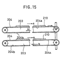
- This pressing device 200 comprises a plurality of compression plates 203 which are arranged in multistage or spaced apart vertically from each other by a predetermined interval and interposed between a fixed plate 201 and a movable plate 202 which are vertically spaced apart from each other, and metal belt conveyers 204 (FIG. 15), the upper portion of each metal belt conveyer 204 being disposed to move over the compression plates 203 and adapted to be intermittently moved from a loading side to an unloading side.
- the loader 206 is movably disposed at the loading side so as to be moved up and down and provided with a plurality of conveyers 205 each arranged to correspond with each of the compression plates 203.
- the unloader 208 is movably disposed at the unloading side so as to be moved up and down and provided, as in the case of the loader 206, with a plurality of conveyers 205 each arranged to correspond with each of the compression plates 203.
- Plates 210 to be treated (hereinafter referred to as untreated plates 210) are successively placed on each conveyer while the loader 206 is vertically moved, and each of the conveyers of the loader 206 is aligned with each of the compression plates 203. Under this condition, the conveyers of the loader 206 and the metal belt conveyers 204 are allowed to move whereby transferring the untreated plates 210 on the conveyers onto the metal belt conveyers 204. Then, the movable plate 202 is moved vertically, thereby rendering the compression plates 203 to approach to each other so as to press each of the untreated plates 210 interposed between the compression plates 203.
- the movable plate 202 is moved downward thereby allowing the space between the compression plates 203 to expand again.
- the metal belt conveyers 204 and the conveyers 207 of the unloader 208 are allowed to move whereby transferring the plates 210 thus pressed onto each of the conveyers of the unloader 208.
- the unloader 208 is moved vertically to successively unload the plates 210 from each of the conveyers 208 toward the unloading conveyers 220.
- the transferring surface (or the upper surface portion) 204a of each of the metal belt conveyers 204 is designed to be moved always in the direction from the loading side to the unloading side (as indicated by the arrow "a").
- the non-transferring surface 204b of the metal belt conveyer 204 which is disposed over the untreated plate 210 is moved in the direction (as indicated by the arrow "b") which is opposite to that of the transferring surface 204a of the metal belt conveyer 204.
- the warped or bent edge portion of the untreated plate 210 may be contacted with the non-transferring surface 204b of the metal belt conveyer 204 that is disposed over the untreated plate 210 and running in the direction opposite to the transferring direction, thus making it difficult to accurately transfer the untreated plate 210 in a predetermined direction and inviting a cause for a fracture of edge portion of the untreated plate 210.
- the aforementioned automatic compression apparatus is accompanied with another problem that when a veneer as an untreated plate is hot-pressed, a sap squeezed out of the veneer due to a pressing of the veneer is likely to be adhered onto the bottom portion of the metal belt conveyer disposed over the veneer and running in a direction opposite to the transferring direction. Therefore, if this metal belt conveyer adhered with the sap is allowed to continue to move for transferring the veneer, the veneer may be transferred back to the loading side instead of being transferred to the unloading side, or may be fractured.
- This invention has been made for the purpose of solving the aforementioned problems accompanied with the conventional apparatus, and therefore an object of the present invention is to provide a veneer-pressing apparatus which is capable of accurately transferring a plurality of veneers even if the edge portion of the veneer is curved or bent upward, thereby accomplishing a pressing treatment.
- this present invention provides a pressing device comprising;
- This present invention also provides a veneer pressing apparatus comprising in addition to the aforementioned pressing device;
- This veneer pressing apparatus can be actuated as follows.
- each of the pressing bodies is moved to the non-pressing position, and the second transfer means is kept to conform with the forward passage.
- the first and second transfer means are allowed to move in the direction conforming to that of the forward passage, and at the same time each of the endless belts is allowed to move whereby transferring a first veneer placed in advance on the first transfer means to the forward transfer passage and then to the second transfer means.
- the second transfer means carrying the first veneer is vertically move to conform with the backward transfer passage.
- a second veneer is put in place on the first transfer means until the aforementioned vertical movement of the second transfer means carrying the first veneer to conform with the backward transfer passage is finished.
- the first transfer means is allowed to move in the direction conforming to that of the forward transfer passage and the second transfer means is allowed to move in the direction conforming to that of the backward transfer passage.
- each of the endless belts is allowed to move whereby transferring the second veneer carried on the first transfer means to the forward transfer passage formed between the pressing bodies, while the first veneer carried on the second transfer means to the backward transfer passage formed between the pressing bodies. Then, the movement of at least the endless belts among the first and second transfer means and the endless belts is suspended.
- the pressing member is actuated to move the pressing bodies to the pressing position respectively, thereby performing the pressing of the first and second veneers.
- FIGS. 1 to 11 depicting one embodiment of this invention.
- a veneer-pressing apparatus 1 comprises a multistage pressing device 2, a first transfer device 4 disposed on the left side of the multistage pressing device 2 and a second transfer device 6 disposed on the right side of the multistage pressing device 2 as shown in FIG. 1.
- the multistage pressing device 2 is designed to press and dry veneers 13a, 13b, 14a and 14b by means of pressing bodies 3, 5, 7, 9 and 11.
- a fixed plate 16 is fixed at the top portion of the main frame 15, and a movable plate 19 is movably attached to the lower portion of the main frame 15.
- This movable plate 19 is connected with a compression member 17 consisting for example of a hydraulic cylinder and spaced apart from the fixed plate 16 by a predetermined distance.
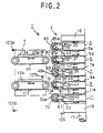
- the main frame 15 is provided with a pair of columns 21 and 23 facing to each other on which sustaining portions 21a to 21e and 23a to 23e are formed respectively as shown in FIG. 4.
- These sustaining portions are formed in steps-like, i.e. the distance between a pair of sustaining portions facing each other (e.g. 21a to 23a) becomes gradually smaller as the location of sustaining portions goes downward from the top of each of columns 21 and 23.
- the pressing bodies 3, 5, 7, 9 and 11 are arranged vertically in five stages between the columns 21 and 23, and are adapted to be heated up to about 150°C by means of heated steam.
- the heating of each of the pressing bodies 3, 5, 7, 9 and 11 may be performed by an electric heater that can be installed inside each of the pressing bodies 3, 5, 7, 9 and 11 instead of employing heated steam.
- Each of the pressing bodies 3, 5, 7, 9 and 11 provided at their corner portions with engagement portions 35, 37, 39, 41 and 43, respectively.
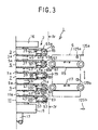
- These engagement portions 35, 37, 39, 41 and 43 are extended back and forth as viewed in FIGS. 2 and 3, and the magnitude of extended length of these engagement portions 35, 37, 39, 41 and 43 becomes gradually smaller as the location of the corresponding pressing body becomes lower so as to be engaged with each of the sustaining portions 21a to 21e and 23a to 23e.
- these engagement portions 35, 37, 39, 41 and 43 are engaged with or rested on each of the sustaining portions 21a to 21e and 23a to 23e so as to sustain the pressing bodies 3, 5, 7, 9 and 11 while keeping them spaced apart from each other by a predetermined distance as shown in FIGS. 2 and 3.
- the grooves 3a, 5a, 7a, 9a and 11a formed on each of the pressing bodies 3, 5, 7, 9 and 11 are formed in such a manner that the grooves facing to each other (e.g. 3a to 5a) are dislocated by a distance (in the running direction) of 6mm.
- Each of the pressing bodies 3, 5, 7, 9 and 11 are provided at both sides thereof (or left and right sides in FIGS. 2 and 3) with arms 45, 47, 49, 51 and 53.
- Driving shafts 55, 57, 59, 61 and 63 are rotatably mounted, via bearings 45a, 47a, 49a, 51a and 53a, on the right side of each of the arms 45, 47 and 51 disposed at the first, second and fourth stages and on the left side of each of the arms 49 and 53 disposed at the third and fifth stages, respectively as shown in FIG. 5.
- Each of these driving shafts 55, 57, 59, 61 and 63 are provided respectively with driving rolls 65, 67, 69, 71 and 73 which are fixed to these driving shafts by means of a known fixing mechanism such as a combination of key and key groove.
- Each of the driving rolls 65, 67, 69, 71 and 73 is formed of a partitioned structure wherein a plurality of rolls (not shown) each having the same axial length are successively mounted along the axial direction thereof.
- Each of the driving rolls 65, 67, 69, 71 and 73 is provided on its peripheral surface with a plurality of engaging protrusions 65a, 67a, 69a, 71a and 73a, each being formed of cone-shape having a height of about 6mm.
- Each of these protrusions 65a, 67a, 69a, 71a and 73a is arranged in a staggered form, i.e. protrusions are spaced apart by an interval of 50mm in the axial direction and by an interval of 25mm in the direction perpendicular to the axial direction, and the neighboring arrays of protrusions running in the axial direction are dislocated by a distance of 25mm from each other.
- fixed shafts 75, 77, 79, 81 and 83 are mounted on the left side of each of the arms 45, 47 and 51 disposed at the first, second and fourth stages and on the right side of each of the arms 49 and 53 disposed at the third and fifth stages, respectively as shown in FIG. 5.
- Each of these fixed shafts 75, 77, 79, 81 and 83 is rotatably attached via a bearing with idler rolls 85, 87, 89, 91 and 93, respectively.
- Each of the idler rolls 85, 87, 89, 91 and 93 is formed of a partitioned structure, as in the case of the aforementioned driving rolls, wherein a plurality of rolls (not shown) each having the same axial length are successively mounted along the axial direction thereof.
- Each of the idler rolls 85, 87, 89, 91 and 93 is provided on its peripheral surface with a plurality of engaging protrusions 85a, 87a, 89a, 91a and 93a, which are arranged in a staggered form as explained in the case of the engaging protrusions 65a, 67a, 69a, 71a and 73a.
- Each of the driving rolls 65, 67, 69, 71 and 73 is linked with the corresponding one of the idler rolls 85, 87, 89, 91 and 93 by one of the endless metal belt 95, 97, 99, 101 and 103 which are wound around each pair of these driving rolls and idler rolls.
- Each of endless metal belt 95, 97, 99, 101 and 103 is formed of an anti-corrosive metallic (e.g.
- These engaging holes 97a and 99a are formed in a pattern which corresponds with that of the aforementioned engaging protrusions 65a, 67a, 69a, 71a, 73a, 85a, 87a, 89a, 91a and 93a and adapted to be engaged with these engaging protrusions 65a, 67a, 69a, 71a, 73a, 85a, 87a, 89a, 91a and 93a.
- a servo-motor (not shown) is mounted on each of the driving shafts 55, 57, 59, 61 and 63, so that the rotation of driving shafts 55, 59 and 63 in counter-clockwise direction as viewed in FIGS. 2 and 3, or the rotation of driving shafts 57 and 61 in clockwise direction as viewed in FIGS. 2 and 3 can be concurrently effected at a constant peripheral speed or the rotation of these driving shafts can be suspended through the control of the servo-motor to be effected based on a control signal from a controlling means to be explained hereinafter.
- the endless metal belt 95, 97, 99, 101 and 103 are actuated to move in the respective direction as indicated by arrows in FIGS.
- a forward transfer passage for transferring a veneer from the first transfer device 4 to the second transfer device 6 is formed between the bottom surface of the metal belt 95 and the upper surface of the metal belt 97, and between the bottom surface of the metal belt 99 and the upper surface of the metal belt 101, while backward transfer passage for transferring a veneer from the second transfer device 6 to the first transfer device 4 is formed between the bottom surface of the metal belt 97 and the upper surface of the metal belt 99, and between the bottom surface of the metal belt 101 and the upper surface of the metal belt 103.
- the aforementioned compression member 17 is designed to successively push up the pressing bodies 3, 5, 7, 9 and 11 from the non-pressing position where the sustaining portions 21a to 21e and 23a to 23e are rested respectively on the engagement portions 35, 37, 39, 41 and 43 to the pressing position, and then to press undried veneers 13a, 13b, 14a and 14b disposed between each pair of the pressing bodies 3, 5, 7, 9 and 11 at a pressure of about 2 kg/cm 2 .
- the main frame 15 of the multistage pressing apparatus 2 is provided with a lower position detector 105 for detecting the position of the movable plate 19 connected to the compression member 17 when the movable plate 19 is descended down as shown in FIGS. 2 and 3, and with a stopper (not shown) for limiting the downward movement of the movable plate 19.
- the first transfer device 4 and the second transfer device 6 which are arranged as shown in FIG. 1 on both sides of this multistage pressing apparatus 2 are constructed as explained below.
- the first transfer device 4 comprises a frame 107 (indicated in FIGS. 2 and 3 by a dot and dash line), a pair of upper conveyer 111 and lower conveyer 113 which are disposed at the upper and lower portions of the frame 107 respectively so as to keep a space therebetween which is equivalent to three stages of the pressing bodies 3, 5, 7, 9 and 11, and a lifting member 119 such as hydraulic cylinder attached to the frame 107, which is adapted to move the frame 107 up and down so as to take an upper position where the level of the upper conveyer 111 conforms with the level of the pressing body 5 of the second stage from the top or to take a lower position where the level of the upper conveyer 111 conforms with the level of the pressing body 9 of the third stage from the top.
- a lifting member 119 such as hydraulic cylinder attached to the frame 107
- the second transfer device 6 comprises a frame 109 (indicated in FIGS. 2 and 3 by a dot and dash line), a pair of upper conveyer 115 and lower conveyer 117, and a lifting member 121.
- the specific structures and functions of these constituent members are the same as explained with reference to the first transfer device 4.
- detectors such as a limit switch
- 123a, 123b, 125a and 125b are disposed at the aforementioned upper position and lower position of the first transfer device 4 and the second transfer device 6, so that when any of the frames 107 and 109 are contacted with any of these detectors 123a, 123b, 125a and 125b, a signal is emitted, and, based on this emitted signal, a control means is actuated to drive or suspend the lifting members 119 and 121 so as to render the first transfer device 4 and the second transfer device 6 to take the aforementioned upper position or lower position. At the same time the positioning of the first transfer device 4 and the second transfer device 6 can be confirmed by these detectors.
- Each of the upper conveyers 111 and 115 and the lower conveyers 113 and 117 is connected with a servo-motor (not shown), which can be controlled on the basis of a driving signal from the control means as explained hereinafter so as to allow the upper conveyers 111 and 115 and the lower conveyers 113 and 117 to be moved in the direction indicated by the arrows shown in FIGS. 2 and 3 at the same speed as that of the metal belts 95, 97, 99, 101 and 103 or to be suspended.
- a servo-motor not shown
- each of the upper conveyers 111 and 115 and the lower conveyers 113 and 117 is provided with a veneer detector 127a, 127b, 129a or 129b, and, based on the detected signal from these veneer detectors 127a, 127b, 129a or 129b, a control means is actuated so as to allow or suspend the movement the upper conveyers 111 and 115 and the lower conveyers 113 and 117. At the same time the presence or absence of a veneer and the passage of the veneer can be confirmed by these detectors.
- the first transfer device 4 and the second transfer device 6 are moved to the upper position by the operation of the lifting members 119 and 121. At this moment, the positioning of the first transfer device 4 and the second transfer device 6 at the upper position is detected by the detectors 123a and 125a.
- the multistage pressing apparatus 2 is conditioned such that the movable plate 19 is moved to the lower position by the returning movement of the compression member 17 thereby allowing the engagement portions 35, 37, 39, 41 and 43 to be rested on the sustaining portions 21a to 21e and 23a to 23e, so that the pressing bodies 3, 5, 7, 9 and 11 are spaced apart from each other by a predetermined distance.
- the positioning of the movable plate 19 at the lower position is detected by the lower position detector 105.
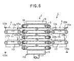
- the upper conveyer 111 and the lower conveyer 113 of the first transfer device 4 are allowed to move in the rightward direction as shown in FIG. 6, and, under this condition, the veneers 13a and 13b each having a thickness of 3mm for instance are placed on the upper conveyer 111 and the lower conveyer 113 respectively so as to transfer them.
- the veneers 13a and 13b are transferred by the upper conveyer 111 and the lower conveyer 113 in this manner, the edges of the veneers 13a and 13b on the downstream side are detected respectively by the veneer detectors 127a and 127b.
- the control means is actuated to render each of the metal belts 95, 97, 99, 101 and 103 to move in the direction as indicated by arrows shown in FIG. 6 and at the same time to render the upper conveyer 115 and the lower conveyer 117 of the second transfer device 6 to move in the rightward direction as indicated by the arrows shown in FIG. 6.
- the veneers 13a and 13b carried on the upper conveyer 111 and the lower conveyer 113 of the first transfer device 4 are then transferred to the metal belts 97 and 101 respectively, from which the veneers 13a and 13b are further transferred to the upper conveyer 115 and the lower conveyer 117 of the second transfer device 6.
- the veneer 13a thus transferred is detected by the veneer detector 129a
- the movement of upper conveyer 115 is suspended by the control means.
- the veneer 13b thus transferred is detected by the veneer detector 129b
- the movement of lower conveyer 117 is suspended by the control means.
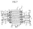
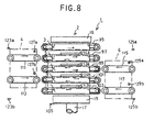
- signals are emitted from the control means so as to allow the upper conveyer 111, the lower conveyer 113 and the metal belts 95, 97, 99, 101 and 103 to move in the same direction as indicated by the arrows in FIG. 8 and to allow the upper conveyer 115 and the lower conveyer 117 to move in the opposite direction (as indicated by the arrows in FIG. 8, i.e. toward the left side).
- These signals are set to continue until the veneers 14a and 14b on each of the upper conveyer 111 and the lower conveyer 113 and the veneers 13a and 13b on each of the upper conveyer 115 and the lower conveyer 117 are shifted a predetermined distance, i.e.
- a pulse oscillator which is capable of emitting the number of pulse in proportion to the running distance of the belt may be used wherein the number of pulse emitted from the pulse oscillator is measured by means of a counter installed in the control means and when the number of count measured by the counter becomes identical with the number of pulse which corresponds to the aforementioned predetermined distance, the output of signal for continuing the movement is suspended.
- the veneers 13a, 13b, 14a and 14b interposed between any pair of the pressing bodies 3, 5, 7, 9 and 11 are heated by the heat from the pressing bodies 3, 5, 7, 9 and 11, thus evaporating the water contained in the veneers 13a, 13b, 14a and 14b.
- the engaging holes 97a and 99a formed in the endless metal belt 95, 97, 99, 101 and 103 are distributed in the specific manner in relative to the grooves 3a, 5a, 7a, 9a and 11a as mentioned above, the engaging holes 97a and 99a of the endless metal belt 95, 97, 99, 101 and 103 are brought to face to the grooves 3a, 5a, 7a, 9a and 11a even if the stopping position of the metal belt 95, 97, 99, 101 and 103 differs from time to time. Accordingly, the water evaporated from the veneers 13a, 13b, 14a and 14b can be effectively discharged to the outer atmosphere through these engaging holes 97a and 99a and grooves 3a, 5a, 7a, 9a and 11a.
- the pressing time of about 5 to 10 minutes may be sufficient for drying these veneers to reduce the water content thereof to about 0 to 15%.
- the pressing of the veneers 13a, 13b, 14a and 14b is continued for a long period of time, the veneers 13a, 13b, 14a and 14b may be cracked due to the shrinkage by drying of the veneers. In order to avoid the generation of the cracking of veneer, this pressing operation may be intermittently performed.
- the compression member 17 may be moved downward thereby returning the movable plate 19 to the original position, thus releasing these veneers from pressing treatment for 20 seconds for instance, and then the compression member 17 is actuated again to press these veneers, thereafter the same processes being repeated required number of times.
- the pressing of the veneers 13a, 13b, 14a and 14b is intermittently released in this manner in the process of drying the veneers, the veneers can be suitably shrunken while inhibiting the generation of cracking of veneer.
- the control means is actuated in such a manner that the lifting member 119 is allowed to return thereby moving the first transfer device 4 to the lower position to take a stand-by position where the position of the first transfer device 4 can be detected by the lower detector 123b and that the lifting member 121 is actuated to move the second transfer device 6 to the upper position to take a stand-by position where the position of the second transfer device 6 can be detected by the upper detector 123a.
- the compression member 17 is lowered to move the movable plate 19 downward according to the control means, and when the movable plate 19 is detected by the lower position detector 105, the returning movement of the compression member 17 is suspended. Accordingly, the pressing bodies 3, 5, 7, 9 and 11 are sustained in an expanded state where the engagement portions 35, 37, 39, 41 and 43 thereof are rested on the sustaining portions 21a to 21e and 23a to 23e, and the pressing bodies 3, 5, 7, 9 and 11 are spaced apart from each other by a predetermined distance as shown in FIG. 10.
- the control means is actuated such that the endless metal belt 95, 97, 99, 101 and 103 are moved in the direction indicated by the arrows shown in FIG. 10, that the upper conveyer 111 and the lower conveyer 113 of the first transfer device 4 taking a stand-by position at the lower position are moved in the leftward direction in FIG. 10, and that the upper conveyer 115 and the lower conveyer 117 of the second transfer device 6 taking a stand-by position at the upper position are moved in the rightward direction in FIG. 10.
- the veneer 14a on the metal belt 97 is transferred onto the upper conveyer 115
- the veneer 13a on the metal belt 99 is transferred onto the upper conveyer 111
- the veneer 14b on the metal belt 101 is transferred onto the lower conveyer 117
- the veneer 13b on the metal belt 103 is transferred onto the lower conveyer 113, thus discharging these veneers out of the veneer-pressing apparatus.
- the veneers 13a, 13b, 14a and 14b which are carried through the movements of the upper conveyers 111 and 115, of the lower conveyers 113 and 117, and of the metal belt 95, 97, 99, 101 and 103, are directly transferred onto the discharge conveyers respectively.
- the control means in this case is actuated such that the metal belt 95, 97, 99, 101 and 103, the upper conveyers 111 and 115, and the lower conveyers 113 and 117 are controlled to continue the movement thereof even if detection signals are output from the veneer detectors 127a, 127b, 129a and 129b when the veneers 13a, 13b, 14a and 14b are transferred respectively from the metal belt 95, 97, 99, 101 and 103 to the corresponding one of the upper conveyers 111 and 115 and the lower conveyers 113 and 117.
- a discharge conveyer (not shown) is disposed on the right side of each of the upper conveyer 115 and the lower conveyer 117 of the second transfer device 6 moved to the upper position so as to be connected with these conveyers 115 and 117 as shown in FIG. 11.
- the veneers 13a, 13b, 14a and 14b which are carried through the movements of the metal belt 95, 97, 99, 101 and 103, of the upper conveyers 111 and 115, and of the lower conveyers 113 and 117, are transferred respectively onto the corresponding one of the upper conveyers 111 and 115 and the lower conveyers 113 and 117.
- the control means in this case is actuated such that the movement of the upper conveyer 115 and the lower conveyer 117 are continued so as to directly transfer the veneers 13a, 13b, 14a and 14b onto the discharge conveyer thereby discharging these veneers.
- the veneers 13a and 13b carried on the upper conveyer 111 and the lower conveyer 113 are detected by the veneer detectors 127a and 127b, the movement of the upper conveyer 111 and the lower conveyer 113 are suspended to take a stand-by state.
- the first transfer device 4 is lifted up to a position where it is detected by the detector 123a and stopped to take a stand-by state, and then the upper conveyer 111 and the lower conveyer 113 are allowed to move in the direction indicated by the arrows shown in FIG. 11, whereby transferring the veneers 13a and 13b via the moving metal belt 95, 97, 99, 101 and 103 onto the upper conveyer 115 and the lower conveyer 117, the veneers 13a and 13b being subsequently transferred on the discharge conveyer so as to be discharged.
- a discharge conveyer (not shown) may be disposed on the left side of each of the upper conveyer 111 and the lower conveyer 113 of the first transfer device 4 moved to the lower position so as to be connected with these conveyers 111 and 113 as shown in FIG. 10.
- the veneers 13a and 13b are allowed to be directly discharged by means of the upper conveyer 111 and the lower conveyer 113.
- the second transfer device 6 is moved to the lower position, and then the upper conveyers 115 and the lower conveyer 117 are allowed to move in a direction opposite to the arrows shown in FIG. 10, whereby transferring and discharging the veneers 14a and 14b via the moving upper and lower conveyers 111 and 113 in the same manner as in the case of the veneers 13a and 13b.
- the veneers 13a, 13b, 14a and 14b which are interposed in the spaces between each pair of the pressing bodies 3, 5, 7, 9 and 11 are transferred by the metal belts 95, 97, 99, 101 and 103 which are adapted be moved in the same direction on both upper and bottom surfaces of these veneers. Therefore, even if the edge portions of the veneers 13a, 13b, 14a and 14b which are curved or bent are contacted with the bottom surfaces of the metal belts 95, 97, 99, 101 and 103 which are disposed over these veneers during the transfer thereof, there is no possibility that the transferring of these veneers would be hindered.
- first transfer device 4 and the second transfer device 6 are designed such that each device is provided with only the upper conveyer (111 and 115) and the lower conveyer (113 and 117), which are less in number as compared with the number of the pressing bodies 3, 5, 7, 9 and 11, and that the running direction and vertical position of each device can be suitably controlled, it is possible to load or unload a larger number of veneers 13a, 13b, 14a and 14b than the number of conveyer in the first transfer device 4 and the second transfer device 6, thus making it possible to minimize the size of the veneer-pressing apparatus 1.
- the passages between the pressing bodies 3 and 5, and between the pressing bodies 7 and 9 are defined as being a forward transfer passage, while the passages between the pressing bodies 5 and 7, and between the pressing bodies 9 and 11 are defined as being a backward transfer passage.
- this is only a matter of nomenclature, so that the passages between the pressing bodies 5 and 7, and between the pressing bodies 9 and 11 may be defined as being a forward transfer passage in FIG. 1, and the first and second veneers may be supplied from the right side of the multistage pressing apparatus 2.
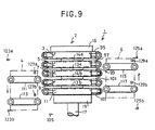
- the first transfer device 4 is descended while the second transfer device 6 is ascended upon receipt of a signal for moving the movable plate 19 upward for the purpose of drying the veneers in FIG. 9.
- these descending and ascending movements may be retarded until the moment when the movable plate 19 is lowered down to the non-pressing position as shown in FIG. 10 after finishing the drying of the veneers so that the metal belts 95, 97, 99, 101 and 103 are ready for moving.
Landscapes
- Life Sciences & Earth Sciences (AREA)
- Engineering & Computer Science (AREA)
- Mechanical Engineering (AREA)
- Wood Science & Technology (AREA)
- Forests & Forestry (AREA)
- Veneer Processing And Manufacture Of Plywood (AREA)
Claims (10)
- Furnierpresse (1) zum gleichzeitigen Pressen einer Vielzahl von Furnieren, aufweisend:eine Vielzahl von Druckkörpern;eine Pressvorrichtung, welche die Vielzahl der in mehreren Etagen angeordneten Druckkörper in senkrechter Richtung trägt (2), wobei die Druckkörper beweglich gemacht werden, und zwar aus einer nicht pressenden Position, wo die Druckkörper (3, 5, 7, 9, 11) vertikal voneinander durch einen vorbestimmten Abstand getrennt sind, in eine Pressposition, in der die Druckkörper nahe beieinander liegen;eine erste Furniertransfervorrichtung (4), angeordnet auf einer Seite der Pressvorrichtung und in der Lage, die Transferrichtung umzukehren; undeine zweite Furniertransfervorrichtung (6), angeordnet auf einer Seite der Pressvorrichtung, welche der genannten einen Seite gegenüberliegt und in der Lage ist, die Transferrichtung umzukehren;hierbei sind die besagten Druckkörper entlang ihrer Oberfläche mit einem Endlosriemen (95, 97, 99, 101, 103) ausgestattet, der in der Lage ist, sich intermittierend um den Druckkörper zu bewegen, wobei er zwischen übereinander angeordneten, benachbarten Druckkörpern Furniertransferwege bildet, deren Transferrichtung alternierend von der Vorwärtsrichtung zur Rückwärtsrichtung wechselt; und die genannten Furniere sind dafür angepasst, gleichzeitig oder separat mit Hilfe der ersten Furniertransfervorrichtung und der zweiten Furniertransfervorrichtung in die Furniertransferwege eingeführt zu werden.
- Furnierpresse zum gleichzeitigen Pressen einer Vielzahl von Furnieren nach Anspruch 1, wobei die genannte erste Furniertransfervorrichtung dafür angepasst ist, ein Furnier in Vorwärtsrichtung in den Furniertransferweg einzuführen, während die genannte zweite Furniertransfervorrichtung dafür angepasst ist, ein Furnier in Rückwärtsrichtung in den Furniertransferweg einzuführen.
- Furnierpresse zum gleichzeitigen Pressen einer Vielzahl von Furnieren nach Anspruch 1, wobei die erste Furniertransfervorrichtung und die zweite Furniertransfervorrichtung so gestaltet sind, dass mindestens ein Kantenabschnitt jeder Vorrichtung, der dem Furniertransferweg gegenüberliegt, in der Lage ist, in senkrechter Richtung seine Position zu ändern, so dass die erste Furniertransfervorrichtung, deren Position in der Weise geändert wurde, dass sie zum Furniertransferweg in Vorwärtsrichtung zeigt, in die Lage versetzt wird, ein Furnier in den Furniertransferweg der Vorwärtsrichtung zuzuführen, womit das Furnier über den Furniertransferweg in Vorwärtsrichtung zur zweiten Furniertransfervorrichtung geführt werden kann, deren Position so geändert wurde, dass sie dem Furniertransferweg in Vorwärtsrichtung gegenüberliegt, während die zweite Furniertransfervorrichtung, die auf diese Weise das Furnier aufgenommen hat, in die Lage versetzt wird, das Furnier in den Furniertransferweg in Rückwärtsrichtung einzuführen, wenn die zweite Furniertransfervorrichtung als Folge der genannten Positionsänderung in eine Stellung gegenüber dem Furniertransferweg in Rückwärtsrichtung gebracht wird.
- Furnierpresse zum gleichzeitigen Pressen einer Vielzahl von Furnieren nach Anspruch 3, wobei die erste Furniertransfervorrichtung, die nach ihrer Positionsänderung dem Furniertransferweg in Vorwärtsrichtung gegenüberliegt, in die Lage versetzt wird, ein zweites Furnier dem Furniertransferweg in Vorwärtsrichtung zuzuführen, während gleichzeitig ein Furnier dem Furniertransferweg in Rückwärtsrichtung durch die zweite Furniertransfervorrichtung zugeführt wird.
- Furnierpresse zum gleichzeitigen Pressen einer Vielzahl von Furnieren nach Anspruch 3 oder 4, wobei die erste Furniertransfervorrichtung, die dem Furniertransferweg in Rückwärtsrichtung nach Positionsänderung gegenüberliegt, so gestaltet ist, dass sie ein Furnier aufnimmt, das gepresst und aus dem Furniertransferweg in Rückwärtsrichtung entladen wurde, während die zweite Furniertransfervorrichtung, die dem Fumiertransferweg in Vorwärtsrichtung nach Positionsänderung gegenüberliegt, so gestaltet ist, dass sie ein Furnier aufnimmt, das gepresst und aus dem Furniertransferweg in Vorwärtsrichtung entladen wurde.
- Furnierpresse zum gleichzeitigen Pressen einer Vielzahl von Furnieren nach Anspruch 5, wobei die erste Furniertransfervorrichtung, die nach ihrer Positionsänderung dem Furniertransferweg in Rückwärtsrichtung gegenüberliegt und ein Furnier aufgenommen hat, das gepresst und aus dem Fumiertransferweg in Rückwärtsrichtung entladen wurde, des Weiteren so gestaltet ist, dass sie dieses Furnier dem Furniertransferweg in Vorwärtsrichtung zuführt, nachdem die erste Furniertransfervorrichtung in ihrer Position so geändert wurde, dass sie dem Furniertransferweg in Vorwärtsrichtung gegenüberliegt, wobei das gepresste Furnier, das dem Fumiertransferweg in Vorwärtsrichtung zugeführt worden ist, so gestaltet ist, dass es über den Furniertransferweg in Vorwärtsrichtung von der zweiten Furniertransfervorrichtung aufgenommen wird, deren Position so geändert wurde, dass sie dem Furniertransferweg in Vorwärtsrichtung gegenüberliegt.
- Furnierpresse zum gleichzeitigen Pressen einer Vielzahl von Furnieren nach Anspruch 5, wobei die zweite Furniertransfervorrichtung, die dem Furniertransferweg in Vorwärtsrichtung nach Positionsänderung gegenüberliegt und ein Furnier aufgenommen hat, das gepresst und aus dem Furniertransferweg in Vorwärtsrichtung entladen wurde, des Weiteren so gestaltet ist, dass sie dieses Furnier dem Furniertransferweg in Rückwärtsrichtung zuführt, nachdem die zweite Furniertransfervorrichtung in ihrer Position so verändert wurde, dass sie dem Furniertransferweg in Rückwärtsrichtung gegenüberliegt, und wobei das gepresste Furnier, das dem Furniertransferweg in Rückwärtsrichtung zugeführt wurde, so gestaltet ist, dass es über den Furniertransferweg in Rückwärtsrichtung durch die erste Furniertransfervorrichtung zugeführt wird, deren Position so geändert wurde, dass sie dem Furniertransferweg in Rückwärtsrichtung gegenüberliegt.
- Furnierpresse zum gleichzeitigen Pressen einer Vielzahl von Furnieren nach einem der Ansprüche 1 bis 7, wobei die Pressvorrichtung mindestens drei parallel zueinander angeordnete Druckkörper aufweist;
hierbei weist die erste Furniertransfervorrichtung eine Transferrichtung auf, welche dieselbe ist wie die des Vorwärtstransferweges;
hierbei ist die zweite Furniertransportrichtung auf einer vorgelagerten Seite des Rückwärtstransferweges angeordnet und kann intermittierend sowohl in Vorwärts- als auch in Rückwärtsrichtung bewegt werden;
eine Steuervorrichtung, die aus einem Steuersystem besteht, wobei, wenn jeder der Druckkörper in eine nicht pressende Position bewegt wird und wenn die zweite Transfervorrichtung so positioniert wird, dass sie mit dem Vorwärtsweg übereinstimmt, die erste und die zweite Transfervorrichtung die Möglichkeit haben, sich in die Richtung zu bewegen, welche mit jener des Vorwärtsweges übereinstimmt, und wobei sich gleichzeitig jeder der Endlosriemen bewegen kann, wodurch ein erstes Furnier, das zuvor auf die erste Transfervorrichtung aufgegeben wurde, auf den Vorwärtstransferweg und anschließend auf die zweite Transfervorrichtung transportiert wird;
und anschließend wird die zweite Transfervorrichtung, welche das erste Furnier trägt, in vertikaler Richtung so bewegt, dass sie mit dem Rückwärtstransferweg übereinstimmt, und ein zweites Furnier wird auf die erste Transfervorrichtung aufgegeben, bis die zuvor erwähnte vertikale Bewegung der zweiten Transfervorrichtung, welche das erste Furnier trägt, abgeschlossen ist, so dass eine Übereinstimmung mit dem Rückwärtstransferweg hergestellt ist;
und unter dieser Bedingung wird es der ersten Transfervorrichtung ermöglicht, sich in der Richtung zu bewegen, die jener des Vorwärtstransferweges entspricht, und der zweiten Transfervorrichtung wird gestattet, sich in der Richtung zu bewegen, die jener des Rückwärtstransferweges entspricht, und gleichzeitig kann sich jeder der Endlosriemen bewegen, wobei das zweite Furnier, das auf der ersten Transfervorrichtung getragen wird, zu dem Vorwärtstransferweg transportiert wird, der zwischen den Druckkörpern gebildet wurde, während das erste Furnier, das auf der zweiten Transfervorrichtung getragen wurde, zu dem von den Druckkörpern gebildeten Rückwärtstransferweg transportiert wird;
und anschließend wird die Bewegung zumindest von den Endlosriemen unter den ersten und zweiten Transfervorrichtungen sowie den Endlosriemen unterbrochen, und unter dieser Bedingung wird das Druckelement betätigt, so dass die Druckkörper jeweils in die Pressposition bewegt werden, wodurch das Pressen des ersten und des zweiten Furniers durchgeführt wird. - Furnierpresse zum gleichzeitigen Pressen einer Vielzahl von Furnieren nach einem der Ansprüche 1 bis 7, aufweisend eine erste Transfervorrichtung, die intermittierend eine erste Transfervorrichtung bewegen kann, die übereinstimmend mit und auf einer im Prozess oberhalb liegenden Seite des Vorwärtstransferweges in der Pressvorrichtung angeordnet ist und die in der Lage ist, sich intermittierend in einer Vorwärtsrichtung zu bewegen, die mit einer Transferrichtung des Vorwärtstransferweges übereinstimmt, und ebenso in einer Richtung entgegengesetzt zu dieser Vorwärtsrichtung, wobei die erste Transfervorrichtung auch in der Lage ist, in vertikaler Richtung so bewegt zu werden, dass sie mit dem Vorwärtsweg oder mit dem Rückwärtsweg übereinstimmt;
die zweite Transfervorrichtung, die in vertikaler Richtung so bewegt werden kann, dass sie mit dem genannten Vorwärtsweg oder dem genannten Rückwärtsweg übereinstimmt;
die aus einem Steuersystem bestehende Steuervorrichtung, wobei dann, wenn jeder der Druckkörper in die nicht pressende Position bewegt wird und wenn die erste und die zweite Transfervorrichtung so positioniert sind, dass sie mit dem ersten Vorwärtsweg übereinstimmen, die erste und die zweite Transfervorrichtung sich in Vorwärtsrichtung bewegen können und wobei sich gleichzeitig jeder der Endlosriemen bewegen kann, wodurch ein erstes Furnier, das zuvor auf die erste Transfervorrichtung aufgegeben wurde, in den Vorwärtstransferweg und anschließend auf die zweite Transfervorrichtung transportiert wird;
und anschließend wird die zweite Transfervorrichtung, die das erste Furnier trägt, vertikal so bewegt, dass sie mit dem Rückwärtstransferweg übereinstimmt, und ein zweites Furnier wird auf die erste Transfervorrichtung aufgegeben, bis die zuvor erwähnte vertikale Bewegung der zweiten Transfervorrichtung, welche das erste Furnier trägt, abgeschlossen ist, so dass sie mit dem Rückwärtstransferweg übereinstimmt;
und unter dieser Bedingung kann sich die erste Transfervorrichtung in Vorwärtsrichtung bewegen, und die zweite Transfervorrichtung kann sich in Rückwärtsrichtung bewegen, und gleichzeitig kann sich jeder der Endlosriemen bewegen, wobei das zweite Furnier, das auf der ersten Transfervorrichtung getragen wird, zu dem Vorwärtstransferweg transportiert wird, der zwischen den Druckkörpern gebildet wird, während das erste Furnier, das auf der zweiten Transfervorrichtung getragen wird, zu dem von den Druckkörpern gebildeten Rückwärtsweg transportiert wird;
und anschließend wird die Bewegung der ersten und zweiten Transfervorrichtung und der Endlosriemen unterbrochen, und unter dieser Bedingung wird das Druckelement betätigt, um die Druckkörper in die jeweilige Pressposition zu bewegen, wobei das Pressen des ersten und zweiten Furniers für eine zuvor festgelegte Zeitdauer durchgeführt wird;
und anschließend wird die Presswirkung des Druckelements gelöst, wodurch sich jeder der Druckkörper in die nicht pressende Position bewegen kann und wodurch das erste und das zweite Furnier aus dem Pressvorgang freigegeben werden;
und anschließend können sich die Endlosriemen bewegen;
die erste Transfervorrichtung wird in eine Position bewegt, die mit dem Rückwärtsweg übereinstimmt, und die zweite Transfervorrichtung wird in eine Position bewegt, die mit dem Vorwärtsweg übereinstimmt, wobei sich die erste Transfervorrichtung in Rückwärtsrichtung und die zweite Transfervorrichtung in Vorwärtsrichtung bewegen kann, nachdem das erste und das zweite Furnier zwischen den Druckkörpern transportiert wurden, jedoch bevor die Betätigung zur Auslösung der Bewegung der Endlosriemen erfolgt ist. - Furnierpresse zum gleichzeitigen Pressen einer Vielzahl von Furnieren nach einem der Ansprüche 1 bis 7, aufweisend eine Pressvorrichtung, die mindestens fünf parallel zueinander angeordnete Druckkörper aufweist, die aus einer nicht pressenden Position, in der die Druckkörper durch einen zuvor festgelegten Abstand in vertikaler Richtung voneinander entfernt sind, in eine Pressposition bewegt werden können, in der die Druckkörper nahe beieinander liegen;
das Druckelement, das in der Lage ist, die genannten mindestens fünf Druckkörper, die mit dem Endlosriemen ausgestattet sind, dazu zu bringen, dass sie sich bewegen, und zwar aus einer nicht pressenden Position, in der die Druckkörper in einem zuvor festgelegten Abstand in vertikaler Richtung voneinander entfernt angeordnet sind, so dass sie abwechselnd zwischen den Druckkörpern den Vorwärtstransferweg und den Rückwärtstransferweg bilden, in eine Pressposition, in der die Druckkörper nahe beieinander liegen, so dass mit einem zuvor festgelegten Druck ein Furnier gepresst wird, das auf jedem der Transferwege getragen wird;
wobei die erste Transfervorrichtung mit mindestens zwei Transferelementen ausgestattet ist, die zueinander in einem Abstand angeordnet sind, der fünf Etagen der genannten Druckkörper entspricht, gemessen zu dem Zeitpunkt, wenn die Druckkörper in der nicht pressenden Position stehen;
wobei die zweite Transfervorrichtung mit mindestens zwei Transferelementen ausgestattet ist, die zueinander in einem Abstand angeordnet sind, der fünf Etagen der genannten Druckkörper entspricht, gemessen zu dem Zeitpunkt, wenn die Druckkörper in der nicht pressenden Position stehen;
eine aus einem Steuersystem bestehende Steuervorrichtung, wobei dann, wenn jeder der Druckkörper in die nicht pressende Position bewegt wird und wenn die erste und die zweite Transfervorrichtung so positioniert sind, dass sie mit dem Vorwärtsweg übereinstimmen, die erste und die zweite Transfervorrichtung sich in Vorwärtsrichtung bewegen können, und gleichzeitig kann sich jeder der Endlosriemen bewegen, wodurch ein erstes Furnier, das zuvor auf jedes der Transferelemente der ersten Transfervorrichtung aufgegeben wurde, auf den Vorwärtstransferweg transportiert wird und anschließend auf jedes der Transferelemente der zweiten Transfervorrichtung;
und anschließend wird die zweite Transfervorrichtung, die das erste Furnier trägt, in vertikaler Richtung so bewegt, dass sie mit dem Rückwärtstransferweg übereinstimmt, und ein zweites Furnier wird auf die erste Transfervorrichtung aufgegeben, und zwar so lange, bis die zuvor erwähnte vertikale Bewegung der zweiten Transfervorrichtung, welche das erste Furnier trägt, abgeschlossen ist, so dass sie mit dem Rückwärtstransferweg übereinstimmt;
und unter dieser Bedingung wird es jedem der Transferelemente der ersten Transfervorrichtung ermöglicht, sich in Vorwärtsrichtung zu bewegen, und jedem der Transferelemente der zweiten Transfervorrichtung wird es ermöglicht, sich in Rückwärtsrichtung zu bewegen, und gleichzeitig kann sich jeder der Endlosriemen bewegen, wodurch das zweite Furnier, das auf jedem der Transferelemente der ersten Transfervorrichtung getragen wird, zu dem Vorwärtstransferweg transportiert wird, der zwischen den Druckkörpern gebildet wird, während das erste Furnier, das auf jedem der Transferelemente der zweiten Transfervorrichtung getragen wird, zu dem zwischen den Druckkörpern gebildeten Rückwärtstransferweg transportiert wird;
und anschließend wird die Bewegung der ersten und zweiten Transfervorrichtung sowie der Endlosriemen unterbrochen, und unter dieser Bedingung wird das Druckelement so betätigt, dass es die Druckkörper in die jeweilige Pressposition bewegt, wodurch das Pressen des ersten und zweiten Furniers während eines zuvor festgelegten Zeitraums ausgeführt wird;
und anschließend wird die Presswirkung des Druckelements gelöst, wodurch sich jeder der Druckkörper in die nicht pressende Position bewegen kann und wodurch das erste und das zweite Furnier aus dem Pressvorgang freigegeben werden;
und anschließend können sich die Endlosriemen bewegen;
jedes der Transferelemente der ersten Transfervorrichtung wird in eine Position bewegt, die mit dem Rückwärtsweg übereinstimmt, und jedes der Transferelemente der zweiten Transfervorrichtung wird in eine Position bewegt, die mit dem Vorwärtsweg übereinstimmt, wobei es jedem der Transferelemente der ersten Transfervorrichtung ermöglicht wird, sich in Rückwärtsrichtung zu bewegen, und jedem der Transferelemente der zweiten Transfervorrichtung, sich in Vorwärtsrichtung zu bewegen, nachdem das erste und das zweite Furnier zwischen den Druckkörpern bewegt wurden, jedoch bevor die Betätigung zur Bewegung der Endlosriemen erfolgt ist, wodurch die ersten Furniere auf dem Rückwärtstransferweg auf jedes der Transferelemente der ersten Transfervorrichtung transportiert werden und wodurch die zweiten Furniere auf dem Vorwärtstransferweg auf jedes der Transferelemente der zweiten Transfervorrichtung transportiert werden.
Applications Claiming Priority (3)
| Application Number | Priority Date | Filing Date | Title |
|---|---|---|---|
| JP238544/96 | 1996-08-20 | ||
| JP23854496A JP3761258B2 (ja) | 1996-08-20 | 1996-08-20 | ベニヤ単板圧締処理装置 |
| JP23854496 | 1996-08-20 |
Publications (3)
| Publication Number | Publication Date |
|---|---|
| EP0830936A2 EP0830936A2 (de) | 1998-03-25 |
| EP0830936A3 EP0830936A3 (de) | 1998-12-09 |
| EP0830936B1 true EP0830936B1 (de) | 2004-02-25 |
Family
ID=17031836
Family Applications (1)
| Application Number | Title | Priority Date | Filing Date |
|---|---|---|---|
| EP97114180A Expired - Lifetime EP0830936B1 (de) | 1996-08-20 | 1997-08-18 | Furnierpresse |
Country Status (11)
| Country | Link |
|---|---|
| US (1) | US5875710A (de) |
| EP (1) | EP0830936B1 (de) |
| JP (1) | JP3761258B2 (de) |
| KR (1) | KR100216862B1 (de) |
| CN (1) | CN1077834C (de) |
| CA (1) | CA2213364C (de) |
| DE (1) | DE69727746T2 (de) |
| ID (1) | ID18050A (de) |
| MY (1) | MY114464A (de) |
| NZ (1) | NZ328564A (de) |
| TW (1) | TW344700B (de) |
Families Citing this family (27)
| Publication number | Priority date | Publication date | Assignee | Title |
|---|---|---|---|---|
| DE19651327A1 (de) * | 1996-12-11 | 1998-06-18 | Danzer Furnierwerke Gmbh | Furnierbügelanlage |
| JP2004209868A (ja) * | 2003-01-07 | 2004-07-29 | Mitsubishi Rayon Co Ltd | 板状製品の製造方法 |
| US7819163B2 (en) | 2003-09-16 | 2010-10-26 | Masonite Corporation | Automated door assembly system and method |
| ITRE20040070A1 (it) * | 2004-06-11 | 2004-09-11 | Diemme Spa | Filtropressa per la formatura di lastre ceramiche e metodo di formatura con essa |
| US20060111786A1 (en) * | 2004-11-22 | 2006-05-25 | Orthopedic Development Corporation | Metallic prosthetic implant for use in minimally invasive acromio-clavicular shoulder joint hemi-arthroplasty |
| DE102007025380A1 (de) * | 2007-05-30 | 2008-12-04 | Robert Bürkle GmbH | Mehretagen-Laminierpresse |
| JP5762679B2 (ja) * | 2009-10-26 | 2015-08-12 | 株式会社新井機械製作所 | 食品生地の熱風乾燥装置 |
| US9314983B2 (en) | 2010-07-28 | 2016-04-19 | Masonite Corporation | Automated door assembly, press, and adhesive therefor |
| US9579818B2 (en) | 2013-03-15 | 2017-02-28 | Masonite Corporation | Automated door assembly and methods, press used therewith, and adhesive therefor |
| ES2602711T3 (es) | 2010-07-28 | 2017-02-22 | Masonite Corporation | Ensamblaje automatizado de puertas |
| DE102011008650A1 (de) * | 2011-01-14 | 2012-07-19 | Robert Bürkle GmbH | Verfahren zum Durchführen einer Bandlaufkorrektur bei einem Förderband einer Presse und Presse mit Förderband und Bandlaufkorektur |
| US9259890B2 (en) * | 2012-07-02 | 2016-02-16 | Taihei Machinery Works, Ltd. | Dewatering method for correcting water content of green veneer for plywood and apparatus for dewatering the green veneer |
| US9511573B2 (en) | 2013-07-25 | 2016-12-06 | Masonite Corporation | Automated door assembly, press, and adhesive therefor |
| US9500408B2 (en) * | 2013-11-01 | 2016-11-22 | Usnr, Llc | Mobile veneer dryer |
| CN104400845A (zh) * | 2014-08-31 | 2015-03-11 | 钟育冰 | 板材冷压裁切组合装置 |
| CN104227806B (zh) * | 2014-10-13 | 2015-12-16 | 浙江安吉双虎竹木业有限公司 | 一种木板冷压机结构 |
| US20190105800A1 (en) * | 2017-10-06 | 2019-04-11 | Alex Xie | Method and apparatus for forming marbelized engineered stone |
| US10738439B2 (en) * | 2018-01-19 | 2020-08-11 | Deere & Company | Open loop electrohydraulic bucket position control method and system |
| CN109435457B (zh) * | 2018-10-24 | 2024-02-09 | 深圳市威利特自动化设备有限公司 | 多层循环隧道炉 |
| CN110466163B (zh) * | 2019-08-18 | 2025-01-28 | 山东金如意木业集团股份有限公司 | 胶合板全自动热压覆膜流水线及其热压覆膜方法 |
| KR102346735B1 (ko) * | 2020-01-09 | 2022-01-03 | 주식회사 영전산기 | 프레스 컨베이어 장치 및 이를 구비한 본딩 설비 |
| CN112092135A (zh) * | 2020-09-14 | 2020-12-18 | 广州飞柯科技有限公司 | 一种木纤维板压合装置及其生产方法 |
| CN112318646B (zh) * | 2020-11-20 | 2022-04-08 | 贵港市欣桐木业有限公司 | 一种用于胶合板加工的压合装置 |
| CN113146771B (zh) * | 2021-06-01 | 2022-04-19 | 南平市华泰木竹有限公司 | 一种高效保量单板干燥工艺方法 |
| FI20216233A1 (en) * | 2021-12-01 | 2023-06-02 | Metso Outotec Finland Oy | HANDLING SYSTEM FOR PART FRAME OF FILTER DISC ASSEMBLY IN A TOWER-TYPE HORIZONTAL FILTER PRESS, METHOD FOR PERFORMING MAINTENANCE OF SUCH PART FRAME AND USE OF SUCH HANDLING SYSTEM |
| CN115816582B (zh) * | 2022-12-19 | 2023-06-27 | 湖南宏森新材料科技有限责任公司 | 一种环保低甲醛生态板热压装置及其生产工艺 |
| CN116749288B (zh) * | 2023-04-27 | 2025-06-03 | 山东百圣源集团有限公司 | 智能化高层多板自动热压机 |
Family Cites Families (13)
| Publication number | Priority date | Publication date | Assignee | Title |
|---|---|---|---|---|
| DE1198543B (de) * | 1962-10-16 | 1965-08-12 | Eugen Siempelkamp | Etagenpresse mit Beschicksieben fuer die Herstellung von Spanplatten, Faserplatten od. dgl. |
| DE1223146B (de) * | 1965-04-17 | 1966-08-18 | Siempelkamp Gmbh & Co | Anlage zur beschickblechlosen Herstellung von Spanplatten, Faserplatten od. dgl. |
| DE1653342A1 (de) * | 1966-10-26 | 1970-03-19 | Zagelow Dipl Ing Guenther | Anlage zum Pressen von Spanplatten oder dergleichen Platten |
| US3896559A (en) * | 1973-03-28 | 1975-07-29 | Martin Jean Marie Michel | Machine for drying by contact veneers obtained by peeling or slicing wood |
| US3964853A (en) * | 1974-11-13 | 1976-06-22 | Becker & Van Hullen Niederrheinische Maschinenfabrik | Apparatus for loading multi-stage heating presses |
| CH582061A5 (de) * | 1975-04-28 | 1976-11-30 | Fahrni Peter | |
| DE2733765A1 (de) * | 1977-07-27 | 1979-02-15 | Buerkle Gmbh & Co Robert | Pressvorrichtung |
| IT1137024B (it) * | 1981-05-22 | 1986-09-03 | Pagnoni Spa | Apparecchiatura di carico e scarico di una pressa bivano per la produzione di pannelli fibrosi di legno o suoi succedanei e procedimento per il suo funzionamento |
| US4863552A (en) * | 1986-02-22 | 1989-09-05 | Taihei Machinery Works, Ltd. | Horizontal multistage press |
| US4811496A (en) * | 1987-10-28 | 1989-03-14 | Meinan Machinery Works, Inc. | Method of correcting the track of an intermittently-running endless belt in a veneer dryer |
| DE4201475A1 (de) * | 1992-01-21 | 1993-07-22 | Hubertus Dipl Ing Hein | Etagenabluefter"- sortier- und pufferfaehige vorrichtung fuer das ablueften und die trocknung von plattenfoermigen erzeugnissen nach dickschichtigem lackauftrag |
| JPH07159028A (ja) * | 1993-12-08 | 1995-06-20 | Yamamoto Tekkosho:Kk | 板状材の熱板乾燥方法 |
| US5560410A (en) * | 1994-10-11 | 1996-10-01 | Peacock; Anthony N. | Veneer drying apparatus and method |
-
1996
- 1996-08-20 JP JP23854496A patent/JP3761258B2/ja not_active Expired - Fee Related
-
1997
- 1997-08-12 US US08/909,821 patent/US5875710A/en not_active Expired - Fee Related
- 1997-08-15 NZ NZ328564A patent/NZ328564A/en unknown
- 1997-08-18 DE DE69727746T patent/DE69727746T2/de not_active Expired - Fee Related
- 1997-08-18 EP EP97114180A patent/EP0830936B1/de not_active Expired - Lifetime
- 1997-08-18 MY MYPI97003777A patent/MY114464A/en unknown
- 1997-08-19 ID IDP972891A patent/ID18050A/id unknown
- 1997-08-19 TW TW086111836A patent/TW344700B/zh active
- 1997-08-19 CA CA002213364A patent/CA2213364C/en not_active Expired - Fee Related
- 1997-08-20 CN CN97119270A patent/CN1077834C/zh not_active Expired - Fee Related
- 1997-08-20 KR KR1019970039638A patent/KR100216862B1/ko not_active Expired - Fee Related
Also Published As
| Publication number | Publication date |
|---|---|
| DE69727746T2 (de) | 2004-12-09 |
| JP3761258B2 (ja) | 2006-03-29 |
| EP0830936A2 (de) | 1998-03-25 |
| JPH1058405A (ja) | 1998-03-03 |
| EP0830936A3 (de) | 1998-12-09 |
| CN1178156A (zh) | 1998-04-08 |
| DE69727746D1 (de) | 2004-04-01 |
| TW344700B (en) | 1998-11-11 |
| KR100216862B1 (ko) | 1999-09-01 |
| MY114464A (en) | 2002-10-31 |
| US5875710A (en) | 1999-03-02 |
| CA2213364C (en) | 2001-01-23 |
| CN1077834C (zh) | 2002-01-16 |
| ID18050A (id) | 1998-02-26 |
| CA2213364A1 (en) | 1998-02-20 |
| KR19980018820A (ko) | 1998-06-05 |
| NZ328564A (en) | 1998-08-26 |
Similar Documents
| Publication | Publication Date | Title |
|---|---|---|
| EP0830936B1 (de) | Furnierpresse | |
| JPH07159028A (ja) | 板状材の熱板乾燥方法 | |
| US3542629A (en) | Method and apparatus for producing and transporting single- and multilayer chipboards | |
| US3887082A (en) | System for handling surface-finishing layers in the production of pressed board | |
| US3389652A (en) | Apparatus for the charging of multiplaten presses | |
| US3077271A (en) | Process and apparatus for charging and discharging multi-level presses | |
| JPH1054662A (ja) | ベニヤ単板の加熱装置 | |
| US3725183A (en) | Automatic plywood layup machine | |
| US3233891A (en) | Stacker | |
| US5123807A (en) | System for stacking veneer sheets conveyed from two different directions | |
| US4424092A (en) | Feed and discharge apparatus for a laminate press | |
| SE502202C2 (sv) | Sätt och anordning för förpressning av fibermaterial vid framställning av skivor | |
| USRE30759E (en) | Method and apparatus for producing and transporting single and multilayer chipboards | |
| JPS56161256A (en) | Stacker for setting veneers together | |
| FI108750B (fi) | Kerrostusvälilevy | |
| JP4781166B2 (ja) | 横型多段プレス装置の板材位置決め構造 | |
| JP2011121235A (ja) | ベニヤ単板の乾燥方法及びベニヤ単板の乾燥装置 | |
| JP2700543B2 (ja) | 多段プレスの熱圧制御方法 | |
| JP4776442B2 (ja) | 横型多段プレス装置の板材搬入構造 | |
| FI74642C (fi) | Mataranordning foer etageskivpress. | |
| US3927612A (en) | Apparatus for charging panels into a press | |
| US5013211A (en) | System for stacking veneer sheets conveyed from two different directions | |
| JPH01279000A (ja) | 横型多段プレスにおける板体搬送方法及び装置 | |
| JP4781167B2 (ja) | 横型多段プレス装置の板材保持構造 | |
| US6595124B1 (en) | Multichamber press |
Legal Events
| Date | Code | Title | Description |
|---|---|---|---|
| PUAI | Public reference made under article 153(3) epc to a published international application that has entered the european phase |
Free format text: ORIGINAL CODE: 0009012 |
|
| AK | Designated contracting states |
Kind code of ref document: A2 Designated state(s): DE FI IT |
|
| PUAL | Search report despatched |
Free format text: ORIGINAL CODE: 0009013 |
|
| AK | Designated contracting states |
Kind code of ref document: A3 Designated state(s): AT BE CH DE DK ES FI FR GB GR IE IT LI LU MC NL PT SE |
|
| 17P | Request for examination filed |
Effective date: 19990609 |
|
| AKX | Designation fees paid |
Free format text: DE FI IT |
|
| 17Q | First examination report despatched |
Effective date: 20020724 |
|
| GRAP | Despatch of communication of intention to grant a patent |
Free format text: ORIGINAL CODE: EPIDOSNIGR1 |
|
| GRAS | Grant fee paid |
Free format text: ORIGINAL CODE: EPIDOSNIGR3 |
|
| RAP1 | Party data changed (applicant data changed or rights of an application transferred) |
Owner name: MEINAN MACHINERY WORKS, INC. |
|
| GRAA | (expected) grant |
Free format text: ORIGINAL CODE: 0009210 |
|
| AK | Designated contracting states |
Kind code of ref document: B1 Designated state(s): DE FI IT |
|
| REF | Corresponds to: |
Ref document number: 69727746 Country of ref document: DE Date of ref document: 20040401 Kind code of ref document: P |
|
| PGFP | Annual fee paid to national office [announced via postgrant information from national office to epo] |
Ref country code: FI Payment date: 20040712 Year of fee payment: 8 |
|
| PGFP | Annual fee paid to national office [announced via postgrant information from national office to epo] |
Ref country code: DE Payment date: 20040828 Year of fee payment: 8 |
|
| PLBE | No opposition filed within time limit |
Free format text: ORIGINAL CODE: 0009261 |
|
| STAA | Information on the status of an ep patent application or granted ep patent |
Free format text: STATUS: NO OPPOSITION FILED WITHIN TIME LIMIT |
|
| 26N | No opposition filed |
Effective date: 20041126 |
|
| PG25 | Lapsed in a contracting state [announced via postgrant information from national office to epo] |
Ref country code: IT Free format text: LAPSE BECAUSE OF NON-PAYMENT OF DUE FEES Effective date: 20050818 Ref country code: FI Free format text: LAPSE BECAUSE OF NON-PAYMENT OF DUE FEES Effective date: 20050818 |
|
| PG25 | Lapsed in a contracting state [announced via postgrant information from national office to epo] |
Ref country code: DE Free format text: LAPSE BECAUSE OF NON-PAYMENT OF DUE FEES Effective date: 20060301 |