EP0830173B1 - Medizinisches kupplungsstück - Google Patents
Medizinisches kupplungsstück Download PDFInfo
- Publication number
- EP0830173B1 EP0830173B1 EP96921504A EP96921504A EP0830173B1 EP 0830173 B1 EP0830173 B1 EP 0830173B1 EP 96921504 A EP96921504 A EP 96921504A EP 96921504 A EP96921504 A EP 96921504A EP 0830173 B1 EP0830173 B1 EP 0830173B1
- Authority
- EP
- European Patent Office
- Prior art keywords
- valve
- conduit
- fluid
- primary
- luer
- Prior art date
- Legal status (The legal status is an assumption and is not a legal conclusion. Google has not performed a legal analysis and makes no representation as to the accuracy of the status listed.)
- Expired - Lifetime
Links
- 239000012530 fluid Substances 0.000 claims abstract description 114
- 238000011144 upstream manufacturing Methods 0.000 claims abstract description 37
- 238000004891 communication Methods 0.000 claims abstract description 16
- 230000007246 mechanism Effects 0.000 claims description 2
- 238000003780 insertion Methods 0.000 claims 1
- 230000037431 insertion Effects 0.000 claims 1
- 239000003814 drug Substances 0.000 description 13
- 229940079593 drug Drugs 0.000 description 12
- 238000002347 injection Methods 0.000 description 10
- 239000007924 injection Substances 0.000 description 10
- 239000008280 blood Substances 0.000 description 6
- 210000004369 blood Anatomy 0.000 description 6
- 239000000463 material Substances 0.000 description 6
- 230000008901 benefit Effects 0.000 description 4
- 238000004519 manufacturing process Methods 0.000 description 4
- 230000000903 blocking effect Effects 0.000 description 2
- 238000010276 construction Methods 0.000 description 2
- 238000000034 method Methods 0.000 description 2
- 238000012986 modification Methods 0.000 description 2
- 230000004048 modification Effects 0.000 description 2
- 230000000284 resting effect Effects 0.000 description 2
- 210000003462 vein Anatomy 0.000 description 2
- 239000002246 antineoplastic agent Substances 0.000 description 1
- 230000002457 bidirectional effect Effects 0.000 description 1
- 230000005540 biological transmission Effects 0.000 description 1
- 229940127089 cytotoxic agent Drugs 0.000 description 1
- 238000006073 displacement reaction Methods 0.000 description 1
- 210000005069 ears Anatomy 0.000 description 1
- 230000008029 eradication Effects 0.000 description 1
- 230000006872 improvement Effects 0.000 description 1
- 238000001990 intravenous administration Methods 0.000 description 1
- 238000007911 parenteral administration Methods 0.000 description 1
- 230000008569 process Effects 0.000 description 1
- 230000004044 response Effects 0.000 description 1
- 238000000926 separation method Methods 0.000 description 1
- 239000004575 stone Substances 0.000 description 1
Images


Classifications
-
- A—HUMAN NECESSITIES
- A61—MEDICAL OR VETERINARY SCIENCE; HYGIENE
- A61M—DEVICES FOR INTRODUCING MEDIA INTO, OR ONTO, THE BODY; DEVICES FOR TRANSDUCING BODY MEDIA OR FOR TAKING MEDIA FROM THE BODY; DEVICES FOR PRODUCING OR ENDING SLEEP OR STUPOR
- A61M39/00—Tubes, tube connectors, tube couplings, valves, access sites or the like, specially adapted for medical use
- A61M39/02—Access sites
-
- A—HUMAN NECESSITIES
- A61—MEDICAL OR VETERINARY SCIENCE; HYGIENE
- A61M—DEVICES FOR INTRODUCING MEDIA INTO, OR ONTO, THE BODY; DEVICES FOR TRANSDUCING BODY MEDIA OR FOR TAKING MEDIA FROM THE BODY; DEVICES FOR PRODUCING OR ENDING SLEEP OR STUPOR
- A61M39/00—Tubes, tube connectors, tube couplings, valves, access sites or the like, specially adapted for medical use
- A61M39/22—Valves or arrangement of valves
- A61M2039/226—Spindles or actuating means
-
- A—HUMAN NECESSITIES
- A61—MEDICAL OR VETERINARY SCIENCE; HYGIENE
- A61M—DEVICES FOR INTRODUCING MEDIA INTO, OR ONTO, THE BODY; DEVICES FOR TRANSDUCING BODY MEDIA OR FOR TAKING MEDIA FROM THE BODY; DEVICES FOR PRODUCING OR ENDING SLEEP OR STUPOR
- A61M2206/00—Characteristics of a physical parameter; associated device therefor
- A61M2206/10—Flow characteristics
- A61M2206/20—Flow characteristics having means for promoting or enhancing the flow, actively or passively
-
- A—HUMAN NECESSITIES
- A61—MEDICAL OR VETERINARY SCIENCE; HYGIENE
- A61M—DEVICES FOR INTRODUCING MEDIA INTO, OR ONTO, THE BODY; DEVICES FOR TRANSDUCING BODY MEDIA OR FOR TAKING MEDIA FROM THE BODY; DEVICES FOR PRODUCING OR ENDING SLEEP OR STUPOR
- A61M39/00—Tubes, tube connectors, tube couplings, valves, access sites or the like, specially adapted for medical use
- A61M39/22—Valves or arrangement of valves
- A61M39/26—Valves closing automatically on disconnecting the line and opening on reconnection thereof
Definitions
- This invention relates to the field of medical devices using a valve for transferring medication intravenously from one location to another. More specifically, this invention is directed to an improvement in medical valves to ensure that the patient receives the entire dosage of medication, while also providing a means for withdrawing blood from the patient.
- the manipulation of fluids for parenteral administration in hospital and medical settings routinely involves the use of connectors for facilitating the movement of fluids between two points. Oftentimes it is desirable to have the patient receive medication from a number of different sources using the same IV. Such a system may be accomplished, for example, by using a Y-connector, a piggy-back connector, a T-connector, or a manifold.
- Such devices have at least one secondary conduit connected with the primary conduit to add one or more secondary fluids, such as drugs, for example, to the primary fluid being infused into a patient through the primary conduit.
- a one-way valving apparatus formed in a manner such that creation of undesirable volumetric dead space is substantially precluded is shown in U.S. Patent No. 4,666,429 to Stone and U.S. Patent No. 3,416,567 to Von Dardel et al.
- a movable element is positioned adjacent to the inner wall of the primary conduit at the junction between the secondary and primary conduits so that the movable element forms a one-way valve.
- the design of the secondary conduit allows the tip of a syringe nozzle to be substantially adjacent to the movable element.
- the movable element is partially displaced due to fluid pressure from the flow of secondary fluid through the secondary conduit toward the primary conduit thereby allowing the secondary fluid to pass by the movable element and enter the primary conduit stream. Once the secondary fluid passes through the junction, the movable element returns to its original position, blocking the junction between the primary and secondary conduits.
- the movable element of the '429 and '567 patents provide only one-way fluid flow, since the movable element is not displaced due to fluid flow in the primary passageway, and therefore, fluid from the patient cannot be drawn into the secondary conduit.
- Two-way valves are advantageous for drawing a patient's blood back to determine if the IV system is property inserted into a patient's vein to provide medication. Further, two-way valves have the additional advantage of having the capacity to withdraw blood samples from the patient.
- a hollow plunger means is extended through the valve means within a housing to provide free fluid communication between the inlet and the outlet of the device through the central passageway of the plunger means.
- a syringe coupled to the inlet may then introduce fluid to the patient or, in the alternative, withdraw fluid from the patient.
- a serious drawback to this prior art device is the large amount of volumetric dead space that exists not only within the central passageway of the plunger means, but also within the passageways of the housing.
- a large amount of the medication to be transferred to the patient remains in the dead space, thereby preventing the delivery of an exact amount of medication.
- the delivery of an exact amount of medication may be critical in some situations when chemotherapeutic agents are being administered or small children are being treated.
- An inexpensive medical connector for transferring medication from a number of different sources using the same IV wherein dead space is minimized and fluid in the secondary conduit is bidirectional would be of great benefit to the medical community.
- the shut-off valve has a "horizontal" member and a perpendicular "vertical” member.
- the horizontal member has an inlet and an outlet.
- the vertical member has an injection orifice for an injection catheter, and a diaphragm positioned underneath the injection orifice.
- the device has an angled orifice in the diaphragm that extends from the injection orifice and a continuous orifice, separate from the angled orifice, for connecting the inlet and outlet. If no injection catheter is connected to the injection orifice, the diaphragm is not compressed and the inlet and outlet are in fluid connection via the continuous orifice.
- the injection catheter compresses the diaphragm, shifting the diaphragm down, thereby closing the continuous orifice and opening the angled orifice establishing a fluid communication between the injection orifice and the outlet ( Figure 2B).
- the diaphragm is completely positioned within the vertical member and, hence, does not extend into the horizontal member.
- the medical connector of this invention has several features, no single one of which is solely responsible for its desirable attributes. Without limiting the scope of this invention as expressed by the claims which follow, its more prominent features will now be discussed briefly. After considering this discussion, and particularly after reading the section entitled “Detailed Description of the Drawings,” one will understand how the features of this invention provide advantages which include safety, reliable and repeatable performance, simplicity of manufacture and use, eradication of dead space, and capacity for one-way or two-way fluid flow.
- the present invention is disclosed in claim 1 and relates to a valve positioned at the intersection of a primary conduit and a secondary conduit of a medical connector.
- the valve of the present invention is a hollow, resilient tube oriented along the longitudinal axis of the primary conduit. The tube, in its resting state, blocks the fluid path to and from the secondary conduit.
- the primary conduit has an inlet at its upstream end and an outlet at its downstream end.
- the primary conduit has an upstream portion defined by the portion between the upstream end and the junction with the secondary conduit, as well as a downstream portion defined by the portion between the downstream end and the junction. Fluid passing through the primary conduit will pass through the hollow valve, but will not be able to enter the secondary conduit of the connector.
- Extending from the exterior side wall of the valve and into the secondary conduit cavity is a tab that is positioned off-center within the cavity of the second conduit.
- the outer diameter of the valve is slightly larger than the inner diameter of the primary conduit of the connector to ensure a fluid-tight fit.
- the secondary conduit may be frusto-conically shaped so as to receive a standard tapered male luer.
- a luer inserted into the secondary conduit may be located in one of two positions. At a first position the tip of the male luer contacts and rests on an annular ring or other protrusion that is integral with or attached to the inner wall of the secondary conduit a short distance above the tab of the valve.
- the annular ring or protrusion may be manufactured of the same plastic or other medically inert material that the medical connector is manufactured from. Alternatively, a tab may be provided within the secondary conduit to provide the same function as the annular ring.
- the luer is inserted to the first position and fluid from a syringe or other medical device in fluid communication with the luer is introduced into the secondary conduit, whereby the resulting fluid pressure partially displaces the resilient valve, allowing fluid from the syringe to pass through the luer and beyond the tube into the primary conduit.
- the resilient valve returns to its original shape, stopping fluid communication between the primary and secondary conduits. Because the distance between the tip of the luer at the first position with respect to the valve is so small, any dead space at the junction between the secondary conduit and the primary conduit is minimized.
- the medical connector and valve of the present invention perform as a fluid pressure-activated one-way valve.
- primary fluid continues to flow through the primary conduit from the upstream end thereof to the downstream end thereof.
- the tip of the luer is pushed further downward and rides over the annular ring or other protrusion, making an auditory "clicking" sound.
- the clicking sound informs the operator that the luer is located in the second position within the secondary conduit.
- the edge of the luer tip engages the tab of the valve and forces the tab downward.
- the walls of the valve accordingly are biased downward and the valve collapses to close off primary fluid flow through the primary conduit upstream of the intersection of the primary and secondary conduits.
- the valve With the male luer in the second position, the valve is maintained in its collapsed position, providing an open passageway to withdraw fluid from the patient to the secondary conduit while effectively maintaining a seal barring fluid flow through the upstream portion of the primary conduit. Since primary fluid flow is sealed off by the collapsed valve, no clamp is required in the primary conduit to pinch off the conduit and prevent primary fluid flow during withdrawal of fluid from the patient. Furthermore, the portion of the valve upstream of the junction maintains a fluid-tight seal against the inner walls of the primary conduit. Such a configuration ensures that no primary fluid is mixed with the patient's blood as the blood is withdrawn into the secondary conduit.
- the present invention provides a pressure-activated valve for injecting fluid into the patient, as well as a luer-activated valve for withdrawing fluid from the patient.
- the present invention overcomes a key problem in the prior art since it provides a one-way and two-way valve with minimal dead space while also being inexpensive to manufacture.
- a movable tab may be attached to the inner wall of the secondary conduit.
- the tip of the male luer contacts and biases the movable tab downward.
- the movable tab forces the resilient valve down to a position where the valve collapses and seals off the primary conduit from primary fluid flow while providing open fluid flow communication between the secondary conduit and the patient.
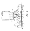
- FIG. 1 illustrates a preferred embodiment of the medical connector 10 of the present invention where the valve 20 is in the closed position.
- Medical connector 10 comprises a primary conduit 11 in fluid communication with a secondary conduit 12 at junction 16.
- the primary conduit 11 has an inlet 13 at its upstream end and an outlet 14 at its downstream end.
- the primary conduit 11 has an upstream portion 26 defined by the portion between the upstream end (inlet 13) and the junction 16 with the secondary conduit 12, as well as a downstream portion 27 defined by the portion between the downstream end (outlet 14) and the junction 16.
- Valve 20 is preferably located at junction 16.
- the longitudinal axis of valve 20 is in alignment with the longitudinal axis of primary conduit 11. Positioned at junction 16 of medical connector 10, valve 20 in its uncompressed state prevents any fluid flow between secondary conduit 12 and primary conduit 11.
- Valve 20 comprises a hollow, resilient tube 24 and tab 21, where the tube 24 is further defined by upstream wall section 23 and downstream wall section 22.
- Tab 21 of valve 20 extends from the side wall of valve 20 into secondary conduit 12.
- Valve downstream wall section 22 extends a short distance downstream in primary conduit 11 beyond junction 16, and valve upstream wall section 23 may extend comparatively a longer distance upstream past junction 16.
- annular ring 15 positioned slightly above tab 21 of valve 20.
- the cavity of secondary conduit 12 tapers inwardly so that secondary conduit 12 may be adapted to fit snug with an ANSI (American National Standards Institute, Washington, D.C.) standard end of a medical implement.
- the implement is a syringe, luer, or any one of a wide variety of conduits used in medical applications.
- a luer is defined as any tube for fluid communication and may also be commonly used with a medical implement. Luers may vary in shape and can be conical, cylindrical, or any other shape known to those of skill in the art.
- the secondary conduit 12 is defined by a proximal end 18 and a distal end which is at junction 16.
- the proximal end 18 of secondary conduit 12 can be equipped with a locking mechanism to facilitate locking of secondary conduit 12 to a variety of medical implements or connector devices.
- locking ears 17 near the proximal opening 18 of secondary conduit 12 are preferably provided, such that the secondary conduit 12 can be locked into any compatible luer-lock device known to those of skill in the art.
- fluid from a primary fluid source enters inlet 13 of primary conduit 11 and flows through tube 24 of valve 20 and out outlet 14 of primary conduit 11 for transmission to the patient.
- the outer diameter of tube 24 is preferably slightly larger than the inner diameter of primary conduit 11. Therefore, a fluid-tight fit is ensured between the valve 20 and the inner wall 29 of the primary conduit 11 to prevent any primary fluid flowing in between the walls of tube 24 and primary conduit 11 and into secondary conduit 12. With the valve 20 in this configuration, no fluid is allowed to flow between secondary conduit 12 and primary conduit 11.
- one-way valving is provided for fluid flow from the medical implement 30 into primary conduit 11 and to the patient.
- the medical implement 30 is inserted into a first position in secondary conduit 12 and fluid from a medical implement 30 is introduced into secondary conduit 12.
- the proximal end 31 of medical implement 30 is inserted into secondary conduit 12 until proximal end 31 contacts annular ring 15. Because annular ring 15 is positioned to be a very short distance from junction 16, dead space between proximal end 31 of medical implement 30 and junction 16 is minimized. With the edges of proximal end 31 resting on annular ring 15, medical implement 30 is in a first position whereupon by injecting fluid through medical implement 30, the resulting fluid pressure partially deflects resilient tube 24 to allow the secondary fluid from medical implement 30 to pass beyond valve 20 and into primary conduit 11 and into the patient. After the secondary fluid from medical implement 30 has passed through junction 16, resilient tube 24 decompresses and returns to its original shape.
- valve 20 The ability of tube 24 of valve 20 to compress under fluid pressure and to return to its original shape is determined by the resiliency of the material used to manufacture the valve 20. By immediately returning to its original shape upon termination of fluid pressure from the medical implement 30, valve 20 prevents any back flow of fluid from outlet 14 to secondary conduit 12. Moreover, because upstream wall section 23 is longer than downstream wall section 22, the fluid pressure introduced by medical implement 30 is not great enough to push the upstream end 28 of tube 24 to overcome its fluid-tight seal with the walls of primary conduit 11. Thus, during this procedure, primary fluid flow from inlet 13 into secondary conduit 12 is prevented.
- the valve 20 may be manufactured from a material that does not require the upstream portion 23 of the tube 24 to be longer than the downstream portion 22 of the tube 24 while still achieving the advantages of the present invention.
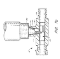
- Figure 3 illustrates the two-way valving feature of the present invention.
- proximal end 31 of medical implement 30 biases tab 21 downward, thereby compressing and maintaining tube 24 in an open, fluid communication position.
- proximal end 31 of medical implement 30 is pushed over annular ring 15, thereby providing an auditory "click" sound as the medical implement 30 is set in the second position.
- This "click" sound is an audible signal which a user may rely upon to indicate that medical implement 30 is locked into the second position within secondary conduit 12.
- the user may be able to determine the position of the medical implement 30 in the secondary conduit 12 by touch and sight, and a audible click would be unnecessary.
- proximal end 31 of medical implement 30 biases tab 21 downward into the passageway of primary conduit 11.
- Tab 21 of valve 20 is specifically designed to be positioned off-center within junction 16 to allow the edge of proximal end 31 to contact tab 21 when medical implement 30 is in the second position.
- Tab 21 can be positioned off-center towards any side of secondary conduit 12. However, in certain embodiments, it is desirable to position tab 21 closer to the downstream end of primary conduit 11.
- tube 24 collapses, as shown in Figure 3, to close off any primary fluid flow in primary conduit 11 from inlet 13. Additionally, upstream wall section 23 also is displaced into the passageway of primary conduit 11, but because upstream wall section 23 is comparatively longer than downstream wall section 22 or alternatively, the strength of the material of the tube 24 does not cause separation of the upstream wall section 23 from the inner walls 29 of primary conduit 11 upstream of the junction 16, the force from medical implement 30 is not great enough to displace the upstream end 28 of upstream wall section 23 from its fluid-tight fit against the inner walls 29 of primary conduit 11. Thus, primary fluid flowing into inlet 13 is completely blocked from entering secondary conduit 12.
- an operator may draw a fluid sample from the patient into medical implement 30.
- the two-way valving feature allows an operator to draw back a small amount of fluid from the patient into medical implement 30 to determine whether the IV system is inserted into the patient's vein so that medication may be safely and properly transmitted to the patient.
- valve 20 acts as a pressure-activated one-way valve for injecting fluid into a patient; and when luer 30 is placed in the second position, valve 20 acts as a two-way valve for introducing or withdrawing fluid from the patient. Due to the limited number of components, the medical connector of the present invention is inexpensive and easy to manufacture.
- valve 20 is a hollow, resilient tube residing within primary conduit 11 at junction 16.
- valve 20 comprises a tube 24 having a upstream wall section 23 and a downstream wall section 22.
- a tab 25 is attached to the inner wall of conduit 12 adjacent junction 16 and beneath annular ring 15.
- Tab 25 serves primarily the same function as tab 21 of Figures 1-3 to maintain downstream wall section 42 of valve 40 in a deformed position so as to provide fluid communication between secondary conduit 12 and primary conduit outlet 14 when medical implement 30 is in the second position.
- Figure 5 illustrates medical implement 30 in the second position within secondary conduit 12.
- proximal end 31 of medical implement 30 Upon riding proximal end 31 of medical implement 30 over annular ring 15 and into the second position, the edge of proximal end 31 biases tab 25 downward into the passageway of primary conduit 11 to displace valve 40 from blocking junction 16, and collapsing downstream wall section 42 to close off upstream primary fluid flow from primary conduit inlet 13.
- tab 25 Upon withdrawal of medical implement 30 from the second position within secondary conduit 12, tab 25 returns to its natural position within secondary conduit 12, allowing resilient tube 44 of valve 40 to return to its original shape.
- annular ring 15 may be substituted for a tab, a protrusion, a ramp, or any other structure known to those of skill in the art.
- annular ring 15 is made of the same material as medical connector 10, that being a plastic or any other medically inert material.
- FIGs 6a and 6b show an alternate embodiment of valve 20 of the present invention that may be used in medical connector 10.
- Valve 20 in Figures 6a and 6b have tab 21 and tube 24 with inner blocks 61 and 62 which seal off upstream primary fluid flow when tab 21 is pressed down by medical implement 30 in the second position.
- Figures 7a and 7b further illustrate the functioning of the alternate embodiment of the valve 20 shown in Figures 6a and 6b.
- Figure 7a shows the valve 20 in the closed position
- Figure 7b shows the valve 20 in the open position.
- FIGs 8a and 8b show another alternate embodiment of valve 20 of the present invention that may be used in medical connector 10.
- Valve 20 in Figures 8a and 8b have tab 21 and tube 24 with inner blocks 81 and 82 which seal off upstream primary fluid flow when tab 21 is pressed down by medical implement 30 when medical implement 30 is in the second position. ( Figure 8b).
- FIGs 9a and 9b show another alternate embodiment of valve 20 of the present invention that may be used in medical connector 10.
- Valve 20 in Figures 9a and 9b have tab 21 and tube 24 with inner blocks 81 and 82 which seal off upstream primary fluid flow when tab 21 is pressed down by medical implement 30 when medical implement 30 is in the second position. Further, tube 24 also collapses when the tab 21 is compressed. ( Figure 9b).
- Figures 10a and 10b show another embodiment of the present invention.
- Two inner blocks 81 and 82 close off primary fluid flow when the medical implement 30 is in the second position with tab 21 compressed as shown in Figure 10b.
- FIGs 11 a and 11b show another embodiment of the valve 20 of the present invention which seals off primary fluid flow upstream when tab 21 is compressed by medical implement 30 as shown in Figure 11b.
- FIGS 12a and 12b show another embodiment of the valve 20 of the present invention which seals off primary fluid flow upstream when medical implement 30 compresses the tab 21 as shown in Figure 12b.
- Valve 20 comprises a tab 21 and a gate 90 where gate 90 seals off primary fluid flow upstream in primary conduit 11 when medical implement 30 is pushed into the second position, thereby biasing tab 21 downward and forcing gate 90 to close.
- FIGs 13a and 13b show another embodiment of the valve 20 of the present invention which seals off primary fluid flow upstream when medical implement 30 compresses the tab 21a or tab 21b as shown in Figure 13b.
- FIGs 14a and 14b show another embodiment of the valve 20 of the present invention which seals off primary fluid flow upstream when medical implement 30 compresses tab 21 as shown in Figure 14b.
Landscapes
- Health & Medical Sciences (AREA)
- Heart & Thoracic Surgery (AREA)
- Pulmonology (AREA)
- Engineering & Computer Science (AREA)
- Anesthesiology (AREA)
- Biomedical Technology (AREA)
- Hematology (AREA)
- Life Sciences & Earth Sciences (AREA)
- Animal Behavior & Ethology (AREA)
- General Health & Medical Sciences (AREA)
- Public Health (AREA)
- Veterinary Medicine (AREA)
- Infusion, Injection, And Reservoir Apparatuses (AREA)
- Materials For Medical Uses (AREA)
- Quick-Acting Or Multi-Walled Pipe Joints (AREA)
Claims (10)
- Medizinischer Verbinder (10) zum Übertragen von Fluids zu und von einem Patienten mit:einem ersten Rohrstück (11), wobei das erste Rohrstück (11) einen stromaufwärtsseitigen Zweig aufweist, der dazu vorgesehen ist, mit einer ersten Fluidquelle in Fluidverbindung gebracht zu werden, und einen stromabwärtsseitigen Zweig, der dazu vorgesehen ist, mit einem Patienten in Fluidverbindung gebracht zu werden;einem mit dem ersten Rohrstück (11) zwischen dem stromaufwärtsseitigen und dem stromabwärtsseitigen Zweig des ersten Rohrstücks (11) in Fluidverbindung stehenden zweiten Rohrstück (12); undeinem hohlen, im allgemeinen rohrförmigen elastischen Ventil (20) mit einem ersten Ende und einem zweiten Ende, wobei das erste Ende im stromaufwärtsseitigen Zweig des ersten Rohrstücks (11) und das zweite Ende im stromabwärtsseitigen Zweig des ersten Rohrstücks (11) angeordnet ist, wobei das Ventil (20) ermöglicht, daß ein erstes Fluid durch das Ventil (20) fließt, wenn das Ventil (20) sich in einem dekomprimierten Zustand befindet, wobei das Ventil (20) einen Ansatz (21) aufweist, der sich in das zweite Rohrstück (21) erstreckt, so daß ein in das zweite Rohrstück (12) eingeführtes Luer-Element den Ansatz (21) zusammendrücken kann, wodurch das Ventil (20) eingedrückt und eine Fluidströmung durch das primäre Rohrstück (11) des Verbinders (10) verhindert wird, während eine Fluidströmung sowohl vom Luer-Element zum Patienten als auch vom Patienten zum Luer-Element ermöglicht wird.
- Medizinischer Verbinder nach Anspruch 1, ferner mit einem entlang einer Innenwand des zweiten Rohrstücks (12) angeordneten Vorsprung.
- Medizinischer Verbinder nach Anspruch 2, wobei der Vorsprung ein ringförmiges Element (15) aufweist.
- Medizinischer Verbinder nach Anspruch 2, wobei der Vorsprung ein Paar Ansätze (25) aufweist, die entlang einer Innenwand des zweiten Rohrstücks (12) angeordnet sind.
- Medizinischer Verbinder nach Anspruch 1, wobei mindestens der Abschnitt des Ventils (20), der im strömungsaufwärtsseitigen Zweig des ersten Rohrstücks (11) angeordnet ist, mit einer Innenwand des ersten Rohrstücks (11) fluiddicht in Eingriff steht, wenn sich das Ventil (20) in einem dekomprimierten Zustand befindet.
- Medizinischer Verbinder nach Anspruch 5, wobei das Ventil (20) dazu geeignet ist, sich zu verformen, wenn ein zweites Fluid vom Luer-Element in das zweite Rohrstück (12) ausgegeben wird, um zu ermöglichen, daß das zweite Fluid in das erste Rohrstück (11) eintritt und dem Patienten zugeführt wird.
- Medizinischer Verbinder nach Anspruch 6, wobei das Ventil (20) so konfiguriert ist, daß es sich auf seine ursprüngliche Position dekomprimiert, nachdem das zweite Fluid vom zweiten Rohrstück (12) zum ersten Rohrstück (11) übertragen wurde.
- Medizinischer Verbinder nach Anspruch 1 mit einer ersten und einer zweiten Position zum Einführen eines Luer-Elements in das zweite Rohrstück (12), und wobei das Luer-Element in der zweiten Position den Ansatz (21) des Ventils (20) vorspannt, so daß das Ventil (20) eingedrückt und verhindert wird, daß ein erstes Fluid das Ventil (20) passiert, während zwischen dem Luer-Element und dem Patienten eine Fluidverbindung aufrechterhalten wird.
- Medizinischer Verbinder nach Anspruch 2, wobei der Verbinder einen hörbaren Ton erzeugt, wenn ein Luer-Element den Vorsprung passiert.
- Medizinischer Verbinder nach Anspruch 1, wobei das zweite Rohrstück (12) ferner einen Verriegelungsmechanismus aufweist, der mit einer Verriegelungsstruktur auf einem Luer-Element in Eingriff gebracht werden kann, um das zweite Rohrstück (12) am Luer-Element zu blockieren.
Applications Claiming Priority (3)
| Application Number | Priority Date | Filing Date | Title |
|---|---|---|---|
| US08/480,615 US5810768A (en) | 1995-06-07 | 1995-06-07 | Medical connector |
| US480615 | 1995-06-07 | ||
| PCT/US1996/009996 WO1996040359A1 (en) | 1995-06-07 | 1996-06-07 | Medical connector |
Publications (2)
| Publication Number | Publication Date |
|---|---|
| EP0830173A1 EP0830173A1 (de) | 1998-03-25 |
| EP0830173B1 true EP0830173B1 (de) | 2001-12-19 |
Family
ID=23908651
Family Applications (1)
| Application Number | Title | Priority Date | Filing Date |
|---|---|---|---|
| EP96921504A Expired - Lifetime EP0830173B1 (de) | 1995-06-07 | 1996-06-07 | Medizinisches kupplungsstück |
Country Status (13)
| Country | Link |
|---|---|
| US (2) | US5810768A (de) |
| EP (1) | EP0830173B1 (de) |
| JP (1) | JPH11507275A (de) |
| KR (1) | KR100446676B1 (de) |
| CN (1) | CN1161165C (de) |
| AT (1) | ATE211007T1 (de) |
| AU (1) | AU6271696A (de) |
| BR (1) | BR9609402A (de) |
| CA (1) | CA2220969A1 (de) |
| DE (1) | DE69618191T2 (de) |
| ES (1) | ES2170242T3 (de) |
| RU (1) | RU2180600C2 (de) |
| WO (1) | WO1996040359A1 (de) |
Cited By (1)
| Publication number | Priority date | Publication date | Assignee | Title |
|---|---|---|---|---|
| WO2023244796A1 (en) * | 2022-06-17 | 2023-12-21 | Human Hydrology Devices | Fluid flow control systems and methods |
Families Citing this family (128)
| Publication number | Priority date | Publication date | Assignee | Title |
|---|---|---|---|---|
| US5470319A (en) | 1994-06-20 | 1995-11-28 | Critical Device Corporation | Needleless injection site |
| US7347828B2 (en) * | 1996-11-25 | 2008-03-25 | Boston Scientific Miami Corporation | Suction adapter for medical instrument |
| JPH10277161A (ja) * | 1997-04-10 | 1998-10-20 | Hakko Denki Seisakusho:Kk | 注入・採取用アダプター |
| US5957898A (en) | 1997-05-20 | 1999-09-28 | Baxter International Inc. | Needleless connector |
| US6095997A (en) * | 1998-03-04 | 2000-08-01 | Corvascular, Inc. | Intraluminal shunt and methods of use |
| US20020156431A1 (en) * | 1998-09-17 | 2002-10-24 | Feith Raymond P. | Multi-valve injection/aspiration manifold with needleless access connection |
| USD453221S1 (en) | 2000-06-12 | 2002-01-29 | Elcam Plastic Cooperative Agricultural Association Ltd. | Luer-type connector |
| US6869653B2 (en) * | 2001-01-08 | 2005-03-22 | Baxter International Inc. | Port tube closure assembly |
| US6652942B2 (en) * | 2001-01-08 | 2003-11-25 | Baxter International Inc. | Assembly for a flowable material container |
| GB0114939D0 (en) * | 2001-06-19 | 2001-08-08 | Angiomed Ag | Luer connector portion |
| US20050021123A1 (en) | 2001-04-30 | 2005-01-27 | Jurgen Dorn | Variable speed self-expanding stent delivery system and luer locking connector |
| US7044441B2 (en) * | 2001-08-10 | 2006-05-16 | Cardinal Health 303, Inc. | Valved male luer connector having sequential valve timing |
| US8540698B2 (en) * | 2004-04-16 | 2013-09-24 | Medrad, Inc. | Fluid delivery system including a fluid path set and a check valve connector |
| US6908459B2 (en) | 2001-12-07 | 2005-06-21 | Becton, Dickinson And Company | Needleless luer access connector |
| ITRM20020071A1 (it) * | 2002-02-11 | 2003-08-11 | Sigma Tau Ind Farmaceuti | Contenitore per flacone di radiofarmaco, e corredo per la sua infusione in un paziente o per il suo trasferimento altrove. |
| ITTO20020276A1 (it) * | 2002-03-27 | 2003-09-29 | Borla Ind | ,,connettore luer lock maschio per linee di fluido medicali,, |
| US7452354B2 (en) * | 2002-06-26 | 2008-11-18 | Inset Technologies Incorporated | Implantable pump connector for catheter attachment |
| RU2328320C2 (ru) * | 2002-11-18 | 2008-07-10 | Новартис Аг | Соединительное устройство комплекта для энтерального введения лекарственных средств |
| US20070142773A1 (en) * | 2003-05-01 | 2007-06-21 | Rosiello Keith M | Methods and system for warming a fluid |
| US7217258B2 (en) * | 2003-05-02 | 2007-05-15 | Becton, Dickinson And Company | Controlled release structure for attaching medical devices |
| CA2529429C (en) | 2003-06-17 | 2009-10-20 | Filtertek Inc. | Fluid handling device and method of making same |
| US7771383B2 (en) * | 2004-10-22 | 2010-08-10 | Medegen, Inc. | Fluid control device with valve and methods of use |
| US7291134B2 (en) * | 2004-10-25 | 2007-11-06 | P. Rowan Smith, Jr. | Medical connector |
| US20060089604A1 (en) * | 2004-10-26 | 2006-04-27 | Intrasafe Medical, Llc | Infusion device for administering fluids to a patient |
| US7338475B2 (en) * | 2004-12-17 | 2008-03-04 | Cardinal Health 303, Inc. | Electret enhanced automatic IV drip chamber shutoff |
| US7670322B2 (en) * | 2005-02-01 | 2010-03-02 | Icu Medical, Inc. | Check valve for medical Y-site |
| US7510545B2 (en) | 2005-02-09 | 2009-03-31 | B. Braun Medical Inc. | Needleless access port valves |
| US7114701B2 (en) * | 2005-03-02 | 2006-10-03 | B. Braun Medical, Inc. | Needleless access port valves |
| US7615035B2 (en) | 2005-03-24 | 2009-11-10 | B. Braun Medical Inc. | Needleless access port valves |
| US8100866B2 (en) * | 2005-03-24 | 2012-01-24 | B. Braun Medical Inc. | Needleless access port valves |
| US7314061B2 (en) | 2005-03-25 | 2008-01-01 | B. Braun Medical Inc. | Needleless access port valves |
| DE602006005674D1 (de) | 2005-07-06 | 2009-04-23 | Vascular Pathways Inc | Gerät zur intravenösen kathetereinführung und verwendungsverfahren |
| DE602006012687D1 (de) | 2005-08-17 | 2010-04-15 | Bard Inc C R | Stentabgabesystem mit variabler geschwindigkeit |
| US20070068587A1 (en) * | 2005-09-29 | 2007-03-29 | Utterberg David S | Slidable valve for fluid flow line |
| USD548343S1 (en) | 2005-10-26 | 2007-08-07 | Smiths Medical Asd, Inc. | Valve element portion for momentary high pressure valve |
| US7302960B2 (en) * | 2005-10-26 | 2007-12-04 | Smiths Medical Asd, Inc. | Momentary high pressure valve |
| USD589142S1 (en) | 2005-11-23 | 2009-03-24 | Intrasafe Medical, Inc. | Infusion device |
| CA2936205C (en) | 2006-01-13 | 2018-08-21 | C.R. Bard, Inc. | Stent delivery system |
| US11026822B2 (en) | 2006-01-13 | 2021-06-08 | C. R. Bard, Inc. | Stent delivery system |
| US8585660B2 (en) * | 2006-01-25 | 2013-11-19 | Navilyst Medical, Inc. | Valved catheter with power injection bypass |
| US7867204B2 (en) | 2006-05-04 | 2011-01-11 | B. Braun Medical Inc. | Needleless access port valves |
| US20070270756A1 (en) * | 2006-05-22 | 2007-11-22 | Peter Peppel | Needleless access port valves |
| US7475701B2 (en) * | 2006-05-24 | 2009-01-13 | Medrad, Inc. | Valve systems and injector system including such valve systems |
| US8062269B2 (en) | 2006-06-09 | 2011-11-22 | Baxter International Inc. | Fail safe dual chamber peritoneal dialysis/infusion system |
| GB0614452D0 (en) * | 2006-07-20 | 2006-08-30 | Young Peter J | Connector system |
| DE202007006190U1 (de) * | 2006-07-31 | 2007-08-23 | B. Braun Melsungen Ag | Kathetervorrichtung |
| US8308691B2 (en) | 2006-11-03 | 2012-11-13 | B. Braun Melsungen Ag | Catheter assembly and components thereof |
| GB0615658D0 (en) | 2006-08-07 | 2006-09-13 | Angiomed Ag | Hand-held actuator device |
| US20080108954A1 (en) * | 2006-11-02 | 2008-05-08 | Jean-Marie Mathias | Flow Controllers |
| US20080108955A1 (en) * | 2006-11-02 | 2008-05-08 | Blickhan Bryan J | Flow Controllers |
| WO2008091292A2 (en) * | 2007-01-19 | 2008-07-31 | Thermics, Llc. | Method and apparatus for warming or cooling a fluid |
| JP4871158B2 (ja) * | 2007-02-08 | 2012-02-08 | 日本コヴィディエン株式会社 | 医療用活栓 |
| ATE548972T1 (de) | 2007-05-07 | 2012-03-15 | Vascular Pathways Inc | Intravenöse kathetereinführungs- und blutprobenvorrichtung |
| WO2008145123A1 (en) | 2007-06-01 | 2008-12-04 | Unomedical A/S | Urine measurement vessel and hose connection |
| US8070189B2 (en) * | 2007-06-20 | 2011-12-06 | Carefusion 303, Inc. | Safety luer connection |
| GB0713497D0 (en) | 2007-07-11 | 2007-08-22 | Angiomed Ag | Device for catheter sheath retraction |
| JP5066403B2 (ja) * | 2007-07-31 | 2012-11-07 | 日本コヴィディエン株式会社 | 液体混注具 |
| JP5066419B2 (ja) * | 2007-09-27 | 2012-11-07 | 日本コヴィディエン株式会社 | 液体混注具 |
| CA2873003C (en) | 2008-05-14 | 2017-06-13 | J&J Solutions, Inc. | Systems and methods for safe medicament transport |
| US8257321B2 (en) | 2008-05-21 | 2012-09-04 | Navilyst Medical, Inc. | Pressure activated valve for high flow rate and pressure venous access applications |
| US8888758B2 (en) * | 2008-09-05 | 2014-11-18 | Carefusion 303, Inc. | Closed male luer device for minimizing leakage during connection and disconnection |
| US8915890B2 (en) * | 2009-07-30 | 2014-12-23 | Becton, Dickinson And Company | Medical device assembly |
| EP2305204A1 (de) * | 2009-09-30 | 2011-04-06 | Fresenius Medical Care Deutschland GmbH | Tubussatz mit Einsatz zur Einführung von Medikamenten |
| CN101822858A (zh) * | 2009-11-25 | 2010-09-08 | 上海普益医疗器械有限公司 | 一种防针刺伤留置针 |
| RU2537781C2 (ru) | 2010-04-05 | 2015-01-10 | Дэниел ПАЙ | Стерильный соединитель с нестерильным изгибаемым кольцом и способ |
| US10384039B2 (en) | 2010-05-14 | 2019-08-20 | C. R. Bard, Inc. | Catheter insertion device including top-mounted advancement components |
| US8932258B2 (en) | 2010-05-14 | 2015-01-13 | C. R. Bard, Inc. | Catheter placement device and method |
| US9872971B2 (en) | 2010-05-14 | 2018-01-23 | C. R. Bard, Inc. | Guidewire extension system for a catheter placement device |
| US9950139B2 (en) | 2010-05-14 | 2018-04-24 | C. R. Bard, Inc. | Catheter placement device including guidewire and catheter control elements |
| US11925779B2 (en) | 2010-05-14 | 2024-03-12 | C. R. Bard, Inc. | Catheter insertion device including top-mounted advancement components |
| MX348044B (es) | 2010-05-27 | 2017-05-25 | J&J Solutions Inc | Sistema de transferencia de fluidos cerrado. |
| FR2961886B1 (fr) * | 2010-06-23 | 2012-08-10 | Braun Medical Sas | Systeme de raccord a deux pieces destine a un tuyau a deux lumieres |
| US8522813B2 (en) * | 2010-09-08 | 2013-09-03 | Covidien Lp | Needleless sampling port |
| GB201017834D0 (en) | 2010-10-21 | 2010-12-01 | Angiomed Ag | System to deliver a bodily implant |
| US8690833B2 (en) | 2011-01-31 | 2014-04-08 | Vascular Pathways, Inc. | Intravenous catheter and insertion device with reduced blood spatter |
| EP2678065B1 (de) | 2011-02-25 | 2019-09-11 | C.R. Bard Inc. | Vorrichtung zum einsetzen medizinischer komponenten mit einer einziehbaren nadel |
| US10076635B2 (en) | 2011-03-08 | 2018-09-18 | Hospi Corporation | Methods and devices for aseptic irrigation, urine sampling, and flow control of urine from a catheterized bladder |
| DK2683435T3 (en) * | 2011-03-08 | 2018-07-23 | Hospi Corp | Devices for aseptic irrigation, urine sampling and urinary flow management from a catheterized bladder |
| US20120261027A1 (en) | 2011-04-18 | 2012-10-18 | Py Daniel C | Needle with closure and method |
| USD903101S1 (en) | 2011-05-13 | 2020-11-24 | C. R. Bard, Inc. | Catheter |
| JP2015519103A (ja) | 2012-04-17 | 2015-07-09 | ドクター ピー インスティチュート エルエルシー | 自閉式コネクタ |
| US10351271B2 (en) | 2012-05-01 | 2019-07-16 | Dr. Py Institute Llc | Device for connecting or filling and method |
| CN104718407A (zh) | 2012-05-01 | 2015-06-17 | 皮博士研究所有限责任公司 | 用于连接或填充的装置及方法 |
| WO2014120741A1 (en) | 2013-01-30 | 2014-08-07 | Vascular Pathways, Inc. | Systems and methods for venipuncture and catheter placement |
| US9750928B2 (en) | 2013-02-13 | 2017-09-05 | Becton, Dickinson And Company | Blood control IV catheter with stationary septum activator |
| US9695323B2 (en) | 2013-02-13 | 2017-07-04 | Becton, Dickinson And Company | UV curable solventless antimicrobial compositions |
| WO2015015675A1 (ja) * | 2013-07-31 | 2015-02-05 | テルモ株式会社 | コネクタ及び輸液セット |
| MX371346B (es) | 2013-08-02 | 2020-01-27 | J&J Solutions Inc D/B/A Corvida Medical | Sistemas para preparacion de compuestos y metodos para el transporte seguro de medicamentos. |
| GB2508570C2 (en) | 2013-08-21 | 2025-07-30 | Braun Melsungen Ag | Catheter assembly |
| KR101348689B1 (ko) * | 2013-09-13 | 2014-01-13 | 장근수 | 다방향 밸브 |
| KR101651092B1 (ko) * | 2014-09-05 | 2016-08-29 | 주식회사 제이엠메디칼 | 주입량 및 주입방향 조절형 밸브 |
| WO2015037928A1 (ko) * | 2013-09-13 | 2015-03-19 | 주식회사 제이엠메디칼 | 다방향 밸브 |
| JP5826815B2 (ja) | 2013-12-11 | 2015-12-02 | 日機装株式会社 | 混注部材 |
| US10376686B2 (en) | 2014-04-23 | 2019-08-13 | Becton, Dickinson And Company | Antimicrobial caps for medical connectors |
| US9675793B2 (en) | 2014-04-23 | 2017-06-13 | Becton, Dickinson And Company | Catheter tubing with extraluminal antimicrobial coating |
| US9789279B2 (en) | 2014-04-23 | 2017-10-17 | Becton, Dickinson And Company | Antimicrobial obturator for use with vascular access devices |
| US20160008569A1 (en) * | 2014-07-08 | 2016-01-14 | Becton, Dickinson And Company | Antimicrobial actuator for opening the side port of a ported catheter |
| US10232088B2 (en) | 2014-07-08 | 2019-03-19 | Becton, Dickinson And Company | Antimicrobial coating forming kink resistant feature on a vascular access device |
| US10232146B2 (en) | 2014-09-05 | 2019-03-19 | C. R. Bard, Inc. | Catheter insertion device including retractable needle |
| DE102014219814A1 (de) | 2014-09-30 | 2016-03-31 | B. Braun Melsungen Ag | Verbindungsvorrichtung für ein Fluidsystem für medizinische Zwecke |
| US9731105B2 (en) * | 2015-02-20 | 2017-08-15 | Carefusion 303, Inc. | Micro infusion device for drug delivery |
| GB2535759B (en) * | 2015-02-26 | 2019-01-16 | Braun Melsungen Ag | IV catheter assemblies with injection ports and related methods |
| CN112915354B (zh) * | 2015-02-26 | 2023-04-11 | B.布劳恩梅尔松根股份公司 | 具有注入端口的iv导管组件 |
| US9682189B2 (en) * | 2015-02-27 | 2017-06-20 | Carefusion 2200, Inc. | Smart check valve |
| SG10201908316RA (en) * | 2015-03-10 | 2019-10-30 | Braun Melsungen Ag | Catheter assemblies with flow control valve mechanisms and related methods |
| USD903100S1 (en) | 2015-05-01 | 2020-11-24 | C. R. Bard, Inc. | Catheter placement device |
| SG10202006540RA (en) | 2015-05-15 | 2020-08-28 | Bard Inc C R | Catheter placement device including an extensible needle safety component |
| CA2999123C (en) | 2015-09-17 | 2020-08-25 | J&J SOLUTIONS, INC. d/b/a Corvida Medical | Medicament vial assembly |
| EP3362114B1 (de) | 2015-10-13 | 2024-03-27 | Cormed Ltd | Automatische compoundierungsvorrichtung für geschlossenes flüssigkeitsübertragungssystem |
| AU2016344428B2 (en) * | 2015-10-28 | 2021-09-30 | Carefusion 303, Inc. | Closed IV access device with y-port needle-free connector |
| US10493244B2 (en) | 2015-10-28 | 2019-12-03 | Becton, Dickinson And Company | Extension tubing strain relief |
| CA3050846A1 (en) | 2016-01-19 | 2017-07-27 | Daniel Py | Single use connectors |
| JP6757401B2 (ja) * | 2016-03-22 | 2020-09-16 | テルモ株式会社 | 医療用コネクタ、輸液セット及び流体の採取方法 |
| JP2016202937A (ja) * | 2016-07-07 | 2016-12-08 | ニプロ株式会社 | ニードルレスコネクター |
| CN109715093B (zh) | 2016-09-12 | 2020-11-06 | C·R·巴德股份有限公司 | 导管插入装置的血液控制 |
| AU2017401073B2 (en) | 2017-03-01 | 2022-06-02 | C. R. Bard, Inc. | Catheter insertion device |
| US11077936B2 (en) * | 2018-01-19 | 2021-08-03 | Textron Innovations Inc. | Fluid delivery device |
| US11389626B2 (en) | 2018-03-07 | 2022-07-19 | Bard Access Systems, Inc. | Guidewire advancement and blood flashback systems for a medical device insertion system |
| CA3103579A1 (en) | 2018-04-24 | 2019-10-31 | Carefusion 303, Inc. | Self-flushing connector |
| RU185384U1 (ru) * | 2018-06-01 | 2018-12-03 | Артем Юрьевич Проваторов | Устройство для соединения медицинских трубок |
| USD921884S1 (en) | 2018-07-27 | 2021-06-08 | Bard Access Systems, Inc. | Catheter insertion device |
| CN109549691A (zh) * | 2018-09-29 | 2019-04-02 | 江苏风和医疗器材股份有限公司 | 用于穿刺器的密封件和穿刺器 |
| BR112021026099A2 (pt) * | 2019-07-09 | 2022-02-15 | Becton Dickinson Co | Conector neuraxial |
| CN213312819U (zh) | 2019-08-19 | 2021-06-01 | 贝克顿·迪金森公司 | 中线导管放置装置 |
| EP4025288A1 (de) | 2019-09-20 | 2022-07-13 | Bard Peripheral Vascular, Inc. | Vorrichtung zum legen eines intravenösen katheters |
| US11389637B2 (en) * | 2021-06-30 | 2022-07-19 | Human Hydrology Devices | Systems and methods for directing fluid flow |
| US20240261541A1 (en) * | 2023-02-03 | 2024-08-08 | Becton, Dickinson And Company | Multi-port distribution hub for vascular access devices |
| CN117244166B (zh) * | 2023-10-13 | 2024-08-16 | 江苏赛腾医疗科技有限公司 | 一种自封式分流插管 |
Family Cites Families (12)
| Publication number | Priority date | Publication date | Assignee | Title |
|---|---|---|---|---|
| US3416567A (en) * | 1964-02-20 | 1968-12-17 | Viggo Ab | Syringe valve |
| US3830241A (en) * | 1972-08-07 | 1974-08-20 | Kendall & Co | Vented adapter |
| US4506691A (en) * | 1984-03-28 | 1985-03-26 | Warner-Lambert Company | Three-way valve for automatic sequencing of fluid flow |
| US4666429A (en) * | 1986-02-26 | 1987-05-19 | Intelligent Medicine, Inc. | Infusion device having improved valving apparatus |
| ATE66622T1 (de) * | 1986-04-11 | 1991-09-15 | Braun Melsungen Ag | Injektions-absperrventil. |
| DE3721299A1 (de) * | 1987-06-27 | 1989-01-12 | Braun Melsungen Ag | Kathetervorrichtung |
| AT391814B (de) * | 1988-11-22 | 1990-12-10 | Hirnich Paul | Anschlussstueck fuer eine infusionseinrichtung od. dgl. |
| US4919167A (en) * | 1989-03-17 | 1990-04-24 | Manska Wayne E | Check valve |
| SE467769B (sv) * | 1991-01-30 | 1992-09-14 | Hemapure Ab Akademiska Sjukhus | Anordning foer anslutning av fluidumledningar foer medicinska aendamaal |
| US5098405A (en) * | 1991-01-31 | 1992-03-24 | Becton, Dickinson And Company | Apparatus and method for a side port cathether adapter with a one piece integral combination valve |
| US5269771A (en) * | 1993-02-24 | 1993-12-14 | Thomas Medical Products, Inc. | Needleless introducer with hemostatic valve |
| US5370624A (en) * | 1993-09-14 | 1994-12-06 | Becton Dickinson And Company | Catheter with deactivatable side port |
-
1995
- 1995-06-07 US US08/480,615 patent/US5810768A/en not_active Expired - Lifetime
-
1996
- 1996-06-07 AU AU62716/96A patent/AU6271696A/en not_active Abandoned
- 1996-06-07 KR KR1019970708960A patent/KR100446676B1/ko not_active Expired - Fee Related
- 1996-06-07 DE DE69618191T patent/DE69618191T2/de not_active Expired - Fee Related
- 1996-06-07 RU RU98100237/14A patent/RU2180600C2/ru not_active IP Right Cessation
- 1996-06-07 WO PCT/US1996/009996 patent/WO1996040359A1/en not_active Ceased
- 1996-06-07 BR BR9609402A patent/BR9609402A/pt not_active IP Right Cessation
- 1996-06-07 ES ES96921504T patent/ES2170242T3/es not_active Expired - Lifetime
- 1996-06-07 CN CNB961945206A patent/CN1161165C/zh not_active Expired - Fee Related
- 1996-06-07 CA CA002220969A patent/CA2220969A1/en not_active Abandoned
- 1996-06-07 AT AT96921504T patent/ATE211007T1/de not_active IP Right Cessation
- 1996-06-07 JP JP9502139A patent/JPH11507275A/ja not_active Ceased
- 1996-06-07 EP EP96921504A patent/EP0830173B1/de not_active Expired - Lifetime
-
1998
- 1998-04-10 US US09/058,648 patent/US6083194A/en not_active Expired - Lifetime
Cited By (2)
| Publication number | Priority date | Publication date | Assignee | Title |
|---|---|---|---|---|
| WO2023244796A1 (en) * | 2022-06-17 | 2023-12-21 | Human Hydrology Devices | Fluid flow control systems and methods |
| US12435807B2 (en) | 2022-06-17 | 2025-10-07 | Human Hydrology Devices | Fluid flow control systems and methods |
Also Published As
| Publication number | Publication date |
|---|---|
| US5810768A (en) | 1998-09-22 |
| DE69618191T2 (de) | 2002-08-22 |
| CN1161165C (zh) | 2004-08-11 |
| US6083194A (en) | 2000-07-04 |
| WO1996040359A1 (en) | 1996-12-19 |
| HK1014884A1 (en) | 1999-10-08 |
| KR19990022479A (ko) | 1999-03-25 |
| BR9609402A (pt) | 1999-07-27 |
| CA2220969A1 (en) | 1996-12-19 |
| ATE211007T1 (de) | 2002-01-15 |
| AU6271696A (en) | 1996-12-30 |
| JPH11507275A (ja) | 1999-06-29 |
| DE69618191D1 (de) | 2002-01-31 |
| RU2180600C2 (ru) | 2002-03-20 |
| EP0830173A1 (de) | 1998-03-25 |
| KR100446676B1 (ko) | 2004-10-14 |
| MX9709242A (es) | 1998-03-31 |
| CN1187139A (zh) | 1998-07-08 |
| ES2170242T3 (es) | 2002-08-01 |
Similar Documents
| Publication | Publication Date | Title |
|---|---|---|
| EP0830173B1 (de) | Medizinisches kupplungsstück | |
| US5395348A (en) | Medical intravenous administration line connectors | |
| US5788215A (en) | Medical intravenous administration line connectors having a luer or pressure activated valve | |
| EP0606363B1 (de) | Ventil für medizinische anwendung | |
| AU2005314266B2 (en) | Self-sealing male luer connector with multiple seals | |
| EP0781151B1 (de) | Ein mit einem ventil versehener infusionsschlauch einer infusionsvorrichtung | |
| EP1447112B1 (de) | Medizinisches Ventil mit positiven Strömungseigenschaften | |
| US5954313A (en) | Medical intravenous administration line connectors having a luer activated valve | |
| US5782816A (en) | Bi-directional valve and method of using same | |
| US5269771A (en) | Needleless introducer with hemostatic valve | |
| US5088984A (en) | Medical connector | |
| CN100475286C (zh) | 具有偏置阀塞的自密封凸形路厄氏连接器 | |
| EP0684050A2 (de) | Nadelfreier Zugang mit Abzweigventil | |
| AU754811B2 (en) | Medical connector | |
| AU2011211445A1 (en) | Self-sealing male luer connector with multiple seals | |
| MXPA97009242A (en) | Med connector | |
| HK1014884B (en) | Medical connector |
Legal Events
| Date | Code | Title | Description |
|---|---|---|---|
| PUAI | Public reference made under article 153(3) epc to a published international application that has entered the european phase |
Free format text: ORIGINAL CODE: 0009012 |
|
| 17P | Request for examination filed |
Effective date: 19971223 |
|
| AK | Designated contracting states |
Kind code of ref document: A1 Designated state(s): AT BE CH DE DK ES FI FR GB GR IE IT LI LU MC NL PT SE |
|
| 17Q | First examination report despatched |
Effective date: 19990707 |
|
| GRAG | Despatch of communication of intention to grant |
Free format text: ORIGINAL CODE: EPIDOS AGRA |
|
| GRAG | Despatch of communication of intention to grant |
Free format text: ORIGINAL CODE: EPIDOS AGRA |
|
| GRAH | Despatch of communication of intention to grant a patent |
Free format text: ORIGINAL CODE: EPIDOS IGRA |
|
| GRAH | Despatch of communication of intention to grant a patent |
Free format text: ORIGINAL CODE: EPIDOS IGRA |
|
| GRAA | (expected) grant |
Free format text: ORIGINAL CODE: 0009210 |
|
| AK | Designated contracting states |
Kind code of ref document: B1 Designated state(s): AT BE CH DE DK ES FI FR GB GR IE IT LI LU MC NL PT SE |
|
| PG25 | Lapsed in a contracting state [announced via postgrant information from national office to epo] |
Ref country code: LI Free format text: LAPSE BECAUSE OF FAILURE TO SUBMIT A TRANSLATION OF THE DESCRIPTION OR TO PAY THE FEE WITHIN THE PRESCRIBED TIME-LIMIT Effective date: 20011219 Ref country code: GR Free format text: LAPSE BECAUSE OF FAILURE TO SUBMIT A TRANSLATION OF THE DESCRIPTION OR TO PAY THE FEE WITHIN THE PRESCRIBED TIME-LIMIT Effective date: 20011219 Ref country code: FI Free format text: LAPSE BECAUSE OF FAILURE TO SUBMIT A TRANSLATION OF THE DESCRIPTION OR TO PAY THE FEE WITHIN THE PRESCRIBED TIME-LIMIT Effective date: 20011219 Ref country code: CH Free format text: LAPSE BECAUSE OF FAILURE TO SUBMIT A TRANSLATION OF THE DESCRIPTION OR TO PAY THE FEE WITHIN THE PRESCRIBED TIME-LIMIT Effective date: 20011219 Ref country code: AT Free format text: LAPSE BECAUSE OF FAILURE TO SUBMIT A TRANSLATION OF THE DESCRIPTION OR TO PAY THE FEE WITHIN THE PRESCRIBED TIME-LIMIT Effective date: 20011219 |
|
| REF | Corresponds to: |
Ref document number: 211007 Country of ref document: AT Date of ref document: 20020115 Kind code of ref document: T |
|
| REG | Reference to a national code |
Ref country code: CH Ref legal event code: EP |
|
| REG | Reference to a national code |
Ref country code: GB Ref legal event code: IF02 |
|
| REG | Reference to a national code |
Ref country code: IE Ref legal event code: FG4D |
|
| REF | Corresponds to: |
Ref document number: 69618191 Country of ref document: DE Date of ref document: 20020131 |
|
| PG25 | Lapsed in a contracting state [announced via postgrant information from national office to epo] |
Ref country code: SE Free format text: LAPSE BECAUSE OF FAILURE TO SUBMIT A TRANSLATION OF THE DESCRIPTION OR TO PAY THE FEE WITHIN THE PRESCRIBED TIME-LIMIT Effective date: 20020319 Ref country code: PT Free format text: LAPSE BECAUSE OF FAILURE TO SUBMIT A TRANSLATION OF THE DESCRIPTION OR TO PAY THE FEE WITHIN THE PRESCRIBED TIME-LIMIT Effective date: 20020319 Ref country code: DK Free format text: LAPSE BECAUSE OF FAILURE TO SUBMIT A TRANSLATION OF THE DESCRIPTION OR TO PAY THE FEE WITHIN THE PRESCRIBED TIME-LIMIT Effective date: 20020319 |
|
| ET | Fr: translation filed | ||
| PG25 | Lapsed in a contracting state [announced via postgrant information from national office to epo] |
Ref country code: MC Free format text: LAPSE BECAUSE OF NON-PAYMENT OF DUE FEES Effective date: 20020607 Ref country code: LU Free format text: LAPSE BECAUSE OF NON-PAYMENT OF DUE FEES Effective date: 20020607 |
|
| REG | Reference to a national code |
Ref country code: CH Ref legal event code: PL |
|
| REG | Reference to a national code |
Ref country code: ES Ref legal event code: FG2A Ref document number: 2170242 Country of ref document: ES Kind code of ref document: T3 |
|
| PLBE | No opposition filed within time limit |
Free format text: ORIGINAL CODE: 0009261 |
|
| STAA | Information on the status of an ep patent application or granted ep patent |
Free format text: STATUS: NO OPPOSITION FILED WITHIN TIME LIMIT |
|
| 26N | No opposition filed | ||
| PGFP | Annual fee paid to national office [announced via postgrant information from national office to epo] |
Ref country code: DE Payment date: 20070531 Year of fee payment: 12 |
|
| PGFP | Annual fee paid to national office [announced via postgrant information from national office to epo] |
Ref country code: NL Payment date: 20070603 Year of fee payment: 12 |
|
| PGFP | Annual fee paid to national office [announced via postgrant information from national office to epo] |
Ref country code: IE Payment date: 20070614 Year of fee payment: 12 |
|
| PGFP | Annual fee paid to national office [announced via postgrant information from national office to epo] |
Ref country code: ES Payment date: 20070717 Year of fee payment: 12 |
|
| PGFP | Annual fee paid to national office [announced via postgrant information from national office to epo] |
Ref country code: GB Payment date: 20070606 Year of fee payment: 12 |
|
| PGFP | Annual fee paid to national office [announced via postgrant information from national office to epo] |
Ref country code: IT Payment date: 20070612 Year of fee payment: 12 |
|
| PGFP | Annual fee paid to national office [announced via postgrant information from national office to epo] |
Ref country code: BE Payment date: 20070821 Year of fee payment: 12 |
|
| PGFP | Annual fee paid to national office [announced via postgrant information from national office to epo] |
Ref country code: FR Payment date: 20070608 Year of fee payment: 12 |
|
| BERE | Be: lapsed |
Owner name: *ICU MEDICAL INC. Effective date: 20080630 |
|
| GBPC | Gb: european patent ceased through non-payment of renewal fee |
Effective date: 20080607 |
|
| NLV4 | Nl: lapsed or anulled due to non-payment of the annual fee |
Effective date: 20090101 |
|
| PG25 | Lapsed in a contracting state [announced via postgrant information from national office to epo] |
Ref country code: BE Free format text: LAPSE BECAUSE OF NON-PAYMENT OF DUE FEES Effective date: 20080630 |
|
| REG | Reference to a national code |
Ref country code: IE Ref legal event code: MM4A |
|
| REG | Reference to a national code |
Ref country code: FR Ref legal event code: ST Effective date: 20090228 |
|
| PG25 | Lapsed in a contracting state [announced via postgrant information from national office to epo] |
Ref country code: IE Free format text: LAPSE BECAUSE OF NON-PAYMENT OF DUE FEES Effective date: 20080609 Ref country code: DE Free format text: LAPSE BECAUSE OF NON-PAYMENT OF DUE FEES Effective date: 20090101 |
|
| PG25 | Lapsed in a contracting state [announced via postgrant information from national office to epo] |
Ref country code: NL Free format text: LAPSE BECAUSE OF NON-PAYMENT OF DUE FEES Effective date: 20090101 |
|
| PG25 | Lapsed in a contracting state [announced via postgrant information from national office to epo] |
Ref country code: GB Free format text: LAPSE BECAUSE OF NON-PAYMENT OF DUE FEES Effective date: 20080607 |
|
| REG | Reference to a national code |
Ref country code: ES Ref legal event code: FD2A Effective date: 20080609 |
|
| PG25 | Lapsed in a contracting state [announced via postgrant information from national office to epo] |
Ref country code: IT Free format text: LAPSE BECAUSE OF NON-PAYMENT OF DUE FEES Effective date: 20080607 Ref country code: FR Free format text: LAPSE BECAUSE OF NON-PAYMENT OF DUE FEES Effective date: 20080630 |
|
| PG25 | Lapsed in a contracting state [announced via postgrant information from national office to epo] |
Ref country code: ES Free format text: LAPSE BECAUSE OF NON-PAYMENT OF DUE FEES Effective date: 20080609 |