EP0829940A2 - Power transmission system, IC card and information communication system using IC card - Google Patents
Power transmission system, IC card and information communication system using IC card Download PDFInfo
- Publication number
- EP0829940A2 EP0829940A2 EP97115472A EP97115472A EP0829940A2 EP 0829940 A2 EP0829940 A2 EP 0829940A2 EP 97115472 A EP97115472 A EP 97115472A EP 97115472 A EP97115472 A EP 97115472A EP 0829940 A2 EP0829940 A2 EP 0829940A2
- Authority
- EP
- European Patent Office
- Prior art keywords
- power
- circuit
- card
- voltage
- induced
- Prior art date
- Legal status (The legal status is an assumption and is not a legal conclusion. Google has not performed a legal analysis and makes no representation as to the accuracy of the status listed.)
- Withdrawn
Links
Images


Classifications
-
- G—PHYSICS
- G06—COMPUTING; CALCULATING OR COUNTING
- G06K—GRAPHICAL DATA READING; PRESENTATION OF DATA; RECORD CARRIERS; HANDLING RECORD CARRIERS
- G06K19/00—Record carriers for use with machines and with at least a part designed to carry digital markings
- G06K19/06—Record carriers for use with machines and with at least a part designed to carry digital markings characterised by the kind of the digital marking, e.g. shape, nature, code
- G06K19/067—Record carriers with conductive marks, printed circuits or semiconductor circuit elements, e.g. credit or identity cards also with resonating or responding marks without active components
- G06K19/07—Record carriers with conductive marks, printed circuits or semiconductor circuit elements, e.g. credit or identity cards also with resonating or responding marks without active components with integrated circuit chips
- G06K19/0723—Record carriers with conductive marks, printed circuits or semiconductor circuit elements, e.g. credit or identity cards also with resonating or responding marks without active components with integrated circuit chips the record carrier comprising an arrangement for non-contact communication, e.g. wireless communication circuits on transponder cards, non-contact smart cards or RFIDs
- G06K19/0726—Record carriers with conductive marks, printed circuits or semiconductor circuit elements, e.g. credit or identity cards also with resonating or responding marks without active components with integrated circuit chips the record carrier comprising an arrangement for non-contact communication, e.g. wireless communication circuits on transponder cards, non-contact smart cards or RFIDs the arrangement including a circuit for tuning the resonance frequency of an antenna on the record carrier
-
- G—PHYSICS
- G06—COMPUTING; CALCULATING OR COUNTING
- G06K—GRAPHICAL DATA READING; PRESENTATION OF DATA; RECORD CARRIERS; HANDLING RECORD CARRIERS
- G06K19/00—Record carriers for use with machines and with at least a part designed to carry digital markings
- G06K19/06—Record carriers for use with machines and with at least a part designed to carry digital markings characterised by the kind of the digital marking, e.g. shape, nature, code
- G06K19/067—Record carriers with conductive marks, printed circuits or semiconductor circuit elements, e.g. credit or identity cards also with resonating or responding marks without active components
- G06K19/07—Record carriers with conductive marks, printed circuits or semiconductor circuit elements, e.g. credit or identity cards also with resonating or responding marks without active components with integrated circuit chips
- G06K19/0701—Record carriers with conductive marks, printed circuits or semiconductor circuit elements, e.g. credit or identity cards also with resonating or responding marks without active components with integrated circuit chips at least one of the integrated circuit chips comprising an arrangement for power management
- G06K19/0715—Record carriers with conductive marks, printed circuits or semiconductor circuit elements, e.g. credit or identity cards also with resonating or responding marks without active components with integrated circuit chips at least one of the integrated circuit chips comprising an arrangement for power management the arrangement including means to regulate power transfer to the integrated circuit
-
- G—PHYSICS
- G06—COMPUTING; CALCULATING OR COUNTING
- G06K—GRAPHICAL DATA READING; PRESENTATION OF DATA; RECORD CARRIERS; HANDLING RECORD CARRIERS
- G06K19/00—Record carriers for use with machines and with at least a part designed to carry digital markings
- G06K19/06—Record carriers for use with machines and with at least a part designed to carry digital markings characterised by the kind of the digital marking, e.g. shape, nature, code
- G06K19/067—Record carriers with conductive marks, printed circuits or semiconductor circuit elements, e.g. credit or identity cards also with resonating or responding marks without active components
- G06K19/07—Record carriers with conductive marks, printed circuits or semiconductor circuit elements, e.g. credit or identity cards also with resonating or responding marks without active components with integrated circuit chips
- G06K19/0723—Record carriers with conductive marks, printed circuits or semiconductor circuit elements, e.g. credit or identity cards also with resonating or responding marks without active components with integrated circuit chips the record carrier comprising an arrangement for non-contact communication, e.g. wireless communication circuits on transponder cards, non-contact smart cards or RFIDs
-
- G—PHYSICS
- G06—COMPUTING; CALCULATING OR COUNTING
- G06K—GRAPHICAL DATA READING; PRESENTATION OF DATA; RECORD CARRIERS; HANDLING RECORD CARRIERS
- G06K7/00—Methods or arrangements for sensing record carriers, e.g. for reading patterns
- G06K7/0008—General problems related to the reading of electronic memory record carriers, independent of its reading method, e.g. power transfer
-
- G—PHYSICS
- G07—CHECKING-DEVICES
- G07C—TIME OR ATTENDANCE REGISTERS; REGISTERING OR INDICATING THE WORKING OF MACHINES; GENERATING RANDOM NUMBERS; VOTING OR LOTTERY APPARATUS; ARRANGEMENTS, SYSTEMS OR APPARATUS FOR CHECKING NOT PROVIDED FOR ELSEWHERE
- G07C9/00—Individual registration on entry or exit
- G07C9/20—Individual registration on entry or exit involving the use of a pass
- G07C9/28—Individual registration on entry or exit involving the use of a pass the pass enabling tracking or indicating presence
-
- H—ELECTRICITY
- H01—ELECTRIC ELEMENTS
- H01Q—ANTENNAS, i.e. RADIO AERIALS
- H01Q1/00—Details of, or arrangements associated with, antennas
- H01Q1/12—Supports; Mounting means
- H01Q1/22—Supports; Mounting means by structural association with other equipment or articles
- H01Q1/2208—Supports; Mounting means by structural association with other equipment or articles associated with components used in interrogation type services, i.e. in systems for information exchange between an interrogator/reader and a tag/transponder, e.g. in Radio Frequency Identification [RFID] systems
- H01Q1/2225—Supports; Mounting means by structural association with other equipment or articles associated with components used in interrogation type services, i.e. in systems for information exchange between an interrogator/reader and a tag/transponder, e.g. in Radio Frequency Identification [RFID] systems used in active tags, i.e. provided with its own power source or in passive tags, i.e. deriving power from RF signal
-
- H—ELECTRICITY
- H01—ELECTRIC ELEMENTS
- H01Q—ANTENNAS, i.e. RADIO AERIALS
- H01Q7/00—Loop antennas with a substantially uniform current distribution around the loop and having a directional radiation pattern in a plane perpendicular to the plane of the loop
- H01Q7/005—Loop antennas with a substantially uniform current distribution around the loop and having a directional radiation pattern in a plane perpendicular to the plane of the loop with variable reactance for tuning the antenna
-
- H—ELECTRICITY
- H02—GENERATION; CONVERSION OR DISTRIBUTION OF ELECTRIC POWER
- H02J—CIRCUIT ARRANGEMENTS OR SYSTEMS FOR SUPPLYING OR DISTRIBUTING ELECTRIC POWER; SYSTEMS FOR STORING ELECTRIC ENERGY
- H02J50/00—Circuit arrangements or systems for wireless supply or distribution of electric power
- H02J50/005—Mechanical details of housing or structure aiming to accommodate the power transfer means, e.g. mechanical integration of coils, antennas or transducers into emitting or receiving devices
-
- H—ELECTRICITY
- H02—GENERATION; CONVERSION OR DISTRIBUTION OF ELECTRIC POWER
- H02J—CIRCUIT ARRANGEMENTS OR SYSTEMS FOR SUPPLYING OR DISTRIBUTING ELECTRIC POWER; SYSTEMS FOR STORING ELECTRIC ENERGY
- H02J50/00—Circuit arrangements or systems for wireless supply or distribution of electric power
- H02J50/10—Circuit arrangements or systems for wireless supply or distribution of electric power using inductive coupling
- H02J50/12—Circuit arrangements or systems for wireless supply or distribution of electric power using inductive coupling of the resonant type
-
- H—ELECTRICITY
- H02—GENERATION; CONVERSION OR DISTRIBUTION OF ELECTRIC POWER
- H02J—CIRCUIT ARRANGEMENTS OR SYSTEMS FOR SUPPLYING OR DISTRIBUTING ELECTRIC POWER; SYSTEMS FOR STORING ELECTRIC ENERGY
- H02J50/00—Circuit arrangements or systems for wireless supply or distribution of electric power
- H02J50/20—Circuit arrangements or systems for wireless supply or distribution of electric power using microwaves or radio frequency waves
-
- H—ELECTRICITY
- H02—GENERATION; CONVERSION OR DISTRIBUTION OF ELECTRIC POWER
- H02J—CIRCUIT ARRANGEMENTS OR SYSTEMS FOR SUPPLYING OR DISTRIBUTING ELECTRIC POWER; SYSTEMS FOR STORING ELECTRIC ENERGY
- H02J50/00—Circuit arrangements or systems for wireless supply or distribution of electric power
- H02J50/80—Circuit arrangements or systems for wireless supply or distribution of electric power involving the exchange of data, concerning supply or distribution of electric power, between transmitting devices and receiving devices
-
- H—ELECTRICITY
- H02—GENERATION; CONVERSION OR DISTRIBUTION OF ELECTRIC POWER
- H02J—CIRCUIT ARRANGEMENTS OR SYSTEMS FOR SUPPLYING OR DISTRIBUTING ELECTRIC POWER; SYSTEMS FOR STORING ELECTRIC ENERGY
- H02J50/00—Circuit arrangements or systems for wireless supply or distribution of electric power
- H02J50/90—Circuit arrangements or systems for wireless supply or distribution of electric power involving detection or optimisation of position, e.g. alignment
Definitions
- the present invention relates to a power transmission system, an IC card and an information communication system using an IC card, wherein commutation tickets, railway tickets, bus tickets, etc. to be used at wickets in railway stations or on buses will be replaced with IC cards, and when an IC card is made to pass a reader/writer, being provided at a wicket in a railway station or on a bus, with noncontact or in close proximity to it, power can be transmitted from the reader/writer to the IC card by radio.
- a signal detector circuit composed of a rectifier D2, a resistor R1 and a capacitor C3 which detects an amplitude-modulated wave superimposed on a AC voltage induced in the receiving coil and transmits the detected data to a main circuit of the data carrier as an input signal, and an amplitude modulator circuit which receives the output signal of the main circuit of the data carrier for switching a transistor T1, and being composed of the transistor T1 which transmits data from the data carrier to the fixed equipment, a capacitor C4 and a resistor R2 are connected to the receiving coil of the data carrier in parallel.
- a resonant circuit is not formed in the receiving coil of the data carrier, so that in a case where the distance between the transmitting coil on the fixed side and the receiving coil on the data carrier side is large, an enough voltage is not induced in the receiving coil and it is made difficult to obtain the power required by the main circuit of the data carrier.
- a half-wave rectifier is adopted in the prior art, a large ripple is produced, which requires a large smoothing capacity; therefore, it is made difficult to incorporate a capacitor of a large capacity in a data carrier in miniaturizing it.
- the purpose of the present invention is to solve the above-mentioned problems and offer an IC card and a power transmission system by radio in which it is made possible to stably supply power by radio from a reader/writer to the internal circuit of an IC card in miniaturizing the elements of a pressure protection circuit and decreasing the temperature rise in a variable impedance circuit provided in an IC card even though the distance between the IC card and the reader/writer may be largely varied.
- Another object of the present invention is to offer an IC card and a power transmission system by radio in which the power can be stably supplied to the internal circuit of the IC card by radio from a reader and/or writer by only making the IC card pass the reader and/or writer with noncontact or in close proximity to it by improving the responsibility of the system in miniaturizing the elements in a pressure protection circuit and decreasing the temperature rise in a variable impedance circuit.
- a further object of the present invention is to offer an IC card and an information communication system using an IC card in which it is made possible to supply power stably from a reader and/or writer to the IC card with noncontact in miniaturizing the elements in the pressure protection circuit and decreasing the temperature rise in the variable impedance circuit provided in the IC card and to perform information communication with high reliability between the reader and/or writer and the IC card.
- Yet another object of the present invention is to offer a power transmission system by radio, an IC card and an information communication system using the IC card.
- the power transmission system by radio it is so arranged that power can be stably supplied even when the distance between an IC card and a reader/writer is largely varied in decreasing the temperature rise in the variable impedance circuit by controlling the static capacity for the induced power received on the IC card side.
- a still further object of the present invention is to offer a power transmission system by radio, an IC card and an information communication system using the IC card.
- the power transmission system by radio it is so arranged that proper power can be stably supplied to the IC card by radio from the power transmission portion of the reader/writer by only passing the IC card through the reader/writer with noncontact or in proximity to it and information can be communicated between the reader/writer and the IC card with high reliability.
- the present invention is a power transmission system in which power is transmitted by radio from a power transmitting device (reader and/or writer device) to an IC card.
- the IC card comprises: an antenna having a resonance circuit for receiving the transmitted radio wave, a full wave rectifier circuit for rectifying an induced power received by the antenna, a power supply circuit which converts a DC voltage output from the full wave rectifier circuit into a power supply voltage, a detector circuit which detects the DC voltage output from the full wave rectifier circuit, an impedance control circuit portion which produces a desired power supply voltage from the DC voltage detected in the detector circuit by controlling the impedance of the circuit, and an internal circuit to be supplied with the desired power supply voltage obtained from the impedance control circuit.
- the present invention is also a power transmission system in which power is transmitted by radio from a power transmission device to an IC card
- the IC card comprises: a receiving portion which receives the transmitted radio wave and produces induced power, a rectifier circuit portion which converts the induced power in the receiving portion into a DC voltage, a variable impedance circuit portion in which the DC voltage obtained in the rectifier circuit is controlled by varying the impedance of the circuit based on the induced power detected in the detector circuit portion or a voltage corresponding to the induced power, and an internal circuit to be supplied with a controlled DC voltage from the variable impedance control circuit.
- the present invention is also a power transmission system in which power is transmitted by radio from the power transmission device to an IC card.
- the transmitted induced power is converted into a DC voltage
- the transmitted induced power or a voltage corresponding to the induced power is detected, and a power supply voltage of a desired DC voltage to be supplied to the internal circuit is obtained by controlling a static capacity based on the detected induced power or a voltage corresponding to the induced power.
- the present invention is a power transmission system in which power is transmitted by radio from a power transmission device to an IC card.
- the IC card comprises: a rectifier circuit which converts the transmitted induced power into a DC voltage, an internal circuit to be supplied with the DC voltage obtained from the rectifier circuit, a detector circuit which detects the transmitted induced power or a voltage corresponding to the induced power, and a static capacity control circuit which obtains a power supply voltage of a desired DC voltage to be supplied to the internal circuit by controlling the static capacity based on the induced voltage or a voltage corresponding to the induced power which is detected in the detector circuit.
- the present invention is a power transmission system in which power is transmitted by radio from a power transmitting device to an IC card.
- the IC card comprises the functions as shown below: the transmitted induced power is converted into a DC voltage to be supplied to an internal circuit, the transmitted induced power or a voltage corresponding to the induced power is detected, and the information about the detected induced power or a voltage corresponding to the induced power is transmitted by radio to the power transmitting device.
- the power transmitted from the power transmitting device is controlled based on the above-mentioned transmitted information.
- the present invention is a power transmission system in which power is transmitted by radio from a power transmitting device to an IC card.
- the IC card comprises the function to convert the transmitted induced power into a DC voltage and to supply the DC voltage to the internal circuit, and also to detect the information concerning the relative position of the IC card to that of the power transmitting device.
- the power transmitted from the power transmission device is controlled based on the above-mentioned detected information.
- the present invention is a power transmission system in which power is transmitted by radio from a power transmitting device to an IC card.
- the IC card comprises the function to convert the transmitted induced power into a DC voltage and to supply the DC voltage to the internal circuit and to detect the information concerning the relative position of the IC card to that of the power transmitting device.
- a desired DC voltage can be obtained in controlling the impedance of a circuit in the IC card based on the detected information.
- the present invention is an IC card which comprises: an antenna having a resonance circuit for receiving a transmitted radio wave, a full wave rectifier circuit for rectifying an induced power received with the antenna, a power supply circuit for converting the DC voltage obtained from the full wave rectifier circuit into a power supply voltage, a detector circuit for detecting the DC voltage rectified in the full wave rectifier circuit, an impedance control circuit which controls the impedance of the circuit for making the detected DC voltage a desired DC voltage and making the power supply voltage converted in the power supply circuit a desired power supply voltage, and an internal circuit to be supplied with the desired power supply voltage obtained from the impedance control circuit portion.
- the present invention is an IC card which comprises: a receiver portion which receives a radio wave to produce an induced power, a rectifier circuit portion for rectifying the induced power generated in the receiver portion to convert the induced power to a DC voltage, a detector circuit portion which detects an induced power obtained in the receiver portion or a voltage corresponding to the induced power, a variable impedance control circuit portion which controls the DC voltage obtained from the rectifier circuit portion based on the induced power detected in the detector circuit portion or a voltage corresponding to the induced power, and an internal circuit to be supplied with a controlled DC voltage from the variable impedance control circuit portion.
- the present invention comprises an IC card in which an impedance in the variable impedance circuit portion is formed with a resistor.
- the present invention is an IC card in which the full wave rectifier circuit, the power supply circuit, the detector circuit, the impedance control circuit, and the internal circuit are composed with one chip.
- the present invention is an IC card which comprises: a receiver portion which receives an induced power by radio, a rectifier circuit portion which rectifies the induced power received in the receiver portion to convert it into a DC voltage, a detector circuit portion which detects the induced power obtained from the receiver portion or a voltage corresponding to the induced power, a static capacity control circuit portion which obtains a desired DC voltage from the rectifier circuit portion by controlling the static capacity based on the induced power detected in the detector circuit portion or a voltage corresponding to the induced power, and an internal circuit which is supplied with a DC voltage from the rectifier circuit portion being controlled by the static capacity control circuit portion.
- the present invention is an information communication system using an IC card which comprises a reader and/or writer device (unit) having an information communication portion and a power transmitting portion and power is transmitted by radio from the power transmitting portion to an IC card.
- the IC card comprises: a rectifier circuit portion which rectifies the induced power transmitted from the reader and/or writer to convert the induced power into a DC voltage, a detector circuit portion which detects the induced power obtained from the receiver portion or a voltage corresponding to the induced power, a variable impedance control circuit portion which controls the impedance of the circuit according to the DC voltage obtained from the rectifier circuit portion based on the induced power detected in the detector circuit portion or a voltage corresponding to the induced power, and an internal circuit which obtains a desired DC voltage from the variable impedance control circuit.
- the information communication system is so designed that an information communication can be performed using a radio wave between the internal circuit of the IC card and the information communication portion of the reader and/or writer device.
- the present invention is so constituted that it is possible to perform information communication by radio between the internal circuit of the IC card and the information communication portion of the reader and/or writer device.
- the present invention is an information communication system using an IC card, which comprises reader and/or writer device having an information communication portion and a power transmission portion and power is transmitted by radio from the power transmitter portion to the IC card by radio.
- the IC card comprises: an antenna having a resonance circuit for receiving a radio wave transmitted from the reader and/or writer device, a full wave rectifier circuit for rectifying the induced power received in the antenna, a power supply circuit which converts the DC voltage rectified in the full wave rectifier circuit into a power supply voltage, a detector circuit which detects the DC voltage rectified in the full wave rectifier circuit, an impedance control circuit which controls the impedance of the circuit to make a detected DC voltage detected in the detector circuit a desired DC voltage and to make the power supply voltage converted in the power supply circuit a desired power supply voltage, and an internal circuit to be supplied with the desired power supply voltage obtained from the impedance control circuit.
- the information communication system is so designed that the information communication can be performed by a radio wave between the internal circuit of the IC card and the information communication portion of the reader and/or writer device.
- the present invention is an information communication system using an IC card which comprises a reader and/or writer device having an information communication portion and a power transmission portion which transmits power from the power transmission portion to the IC card by radio.
- the IC card following operations are performed: the induced power transmitted from the reader and/or writer device is converted into a DC voltage and it is supplied to the internal circuit, the induced power transmitted to the IC card or a voltage corresponding to the induced power is detected, and the information concerning the detected induced power or the voltage corresponding to the induced power is transmitted to the power transmission portion of the reader and/or writer device by radio.
- the reader and/or writer controls the power to be transmitted from the power transmission portion based on the information sent from the IC card.
- the information communication system is so designed that information communication can be performed between the internal circuit of the IC card and the information communication portion of the reader and/or writer device.
- the present invention is an information communication system using an IC card, wherein the transmission of power by radio from the reader and/or writer to the IC card and the communication of information by radio between the internal circuit of the IC card and the information communication portion of the reader and/or writer device are performed with a common antenna.
- the present invention is an information communication system, using an IC card, wherein the reader and/or writer device comprises: a power supply portion which generates a signal to be used for the transmission of power, an encoder circuit for encoding input data for transmission, a modulator which executes amplitude modulation of a signal obtained from the encoder circuit and superimposes it on the signal obtained from the power supply portion, a feeder circuit for feeding power based on the signal obtained from the modulator, and an antenna for generating a radio wave corresponding to the fed current by the feeder circuit.
- the reader and/or writer device comprises: a power supply portion which generates a signal to be used for the transmission of power, an encoder circuit for encoding input data for transmission, a modulator which executes amplitude modulation of a signal obtained from the encoder circuit and superimposes it on the signal obtained from the power supply portion, a feeder circuit for feeding power based on the signal obtained from the modulator, and an antenna for generating a radio wave corresponding to the fed current by the feeder circuit
- the present invention is an information communication system using an IC card, wherein the internal circuit of the IC card comprises: a decoder circuit which performs waveform shaping and decodes a modulated wave for communication detected by the antenna, a microcomputer which inputs received data decoded in the decoder circuit and outputs transmission data, an encoder circuit which encodes the transmitting data output from the microcomputer, and a modulator which modulates a signal and inputs it to the antenna based on the signal encoded in the encoder circuit.
- the above-mentioned constitution it is made possible to realize a power transmission system by radio and an IC card, wherein even though the distance between the IC card and the reader and/or writer device (power transmitting device) is largely varied, power can be stably transmitted by radio from the reader and/or writer device to the internal circuit of the IC card in miniaturizing a pressure protection circuit provided in the IC card and decreasing the temperature rise in a variable impedance circuit.
- the realization of miniaturization of the elements of the pressure protection circuit and the low temperature rise in the variable impedance circuit made it possible to constitute an IC card with an antenna for receiving a radio wave and elements of one-chip constitution, which caused to realize a low cost IC card.
- a power transmission system by radio and an IC card can be realized, wherein power can be transmitted from the reader and/or writer device to the IC card by radio using a coil-shaped antenna or a spiral antenna on the IC card, and power can be supplied stably by radio from the reader and/or writer device to the internal circuit of the IC card by only making an IC card pass the reader and/or writer device with noncontact or in the proximity to it in miniaturizing the elements in the pressure protection circuit, decreasing the temperature rise in the variable impedance circuit, and improving the responsibility of the circuit.
- a power transmission system by radio, an IC card, and an information communication system using an IC card can be realized, wherein power can be stably supplied to the IC card even though the distance between the IC card and the reader and/or writer is largely varied in decreasing the temperature rise in the variable impedance circuit by controlling the induced power received on the side of the IC card by varying the static capacity in the variable impedance circuit.
- a power transmission system by radio, an IC card, and an information communication system using the IC card can be realized, wherein proper power can be transmitted from the power transmission portion of the reader and/or writer device to the IC card by radio by only making the IC card pass the reader and/or writer with noncontact or in proximity to it.
- power is stably supplied to the internal circuit of the IC card, and the communication of information of high reliability can be performed between the reader and/or writer device and the IC card.
- an information communication system using an IC card can be realized, wherein power is stably supplied from the reader and/or writer to the IC card with noncontact, and the communication (transmission and reception) of information of high reliability can be performed between the reader and/or writer device and the IC card.
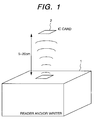
- Fig. 1 is a schematic view of a power transmission system according to the present invention in which power is transmitted by radio from a reader and/or writer 1 provided at a wicket in a railway station or on a bus to an IC card 2 which is to be passed the reader and/or writer 1 with noncontact or in proximity to it.
- the IC card 2 is passed the reader and/or writer 1 provided at the wicket in a railway station or on a bus by an user with noncontact, at a distance of about 5 to 20 cm.
- the information concerning railway tickets, commutation tickets, etc. is communicated by radio between the reader and/or writer and the IC card; thereby, the IC card will be able to perform the role of a railway ticket, commutation ticket, or the like.
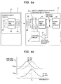
- FIG. 2 shows a schematic view of a power transmission system by radio according to the present invention.
- a reference numeral 21 denotes a power supply circuit in the reader and/or writer 1 provided at a wicket in a railway station or on a bus.
- the power supply circuit 21 comprises: a power supply 22 which generates a high frequency voltage of 13.56 MHz, an impedance matching circuit 23 which prevents reflection at a junction point, and a coil 24 which transmits power of about 2 to 5 W of 13.56 MHz by radio.
- the IC card comprises an induced voltage generator portion 28 which is composed of a coil 26 which receives power by radio from the power supply circuit 21 provided in the reader and/or writer and a rectifier circuit 27 which converts the high frequency power received by the coil 26 into a DC voltage of the order of 7 to 15 V, and an internal circuit 29 (constituted with an IC chip, for example) which is operated with a DC voltage of the order of 7 to 10 V generated in the induced voltage generator portion 28.
- a resonance circuit with a tuning capacitor 25 is provided in the coil 26 to be able to obtain a large induced voltage.
- the coil 26 has a multilayer structure of more than 2 layers in which a spiral-shaped antenna coil is wound continuously in the same direction, so that stray capacitance between windings and the inductance of the coil may constitute a resonance circuit. As a result, a tuning capacitor 25 may not be needed or an extremely small one will do the work.
- a coil (a coil-shaped or spiral-shaped antenna) 24 and a coil (a coil-shaped or spiral-shaped antenna) 26 are used for the purpose of improving the responsibility of the system to be able to supplying power to the internal circuit ( constituted with an IC chip, for example) of the IC card 2 in less than 0.1 sec. It has a merit to improve the strength of the IC card 2 against deformation by forming the coil 26 on the IC card 2. Therefore, if it is possible to transmit power to the internal circuit 29 of the IC card 2 in less than 0.1 sec., a light emitting element and a light receiving element can be used in place of the coils 24 and 26.
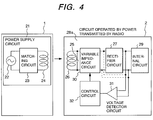
- Fig. 3 shows the relation between d and VL, where d denotes the distance between the coil 24 of the power supply circuit 21 provided in a reader and/or writer 1 and the IC card 25, and VL denotes the induced voltage obtained from the rectifier circuit 27. As shown in Fig.
- the induced voltage VL obtained from the rectifier circuit 27 shall be constantly controlled to be in the allowable range of the induced voltage, from Vmin to Vmax, even when an IC card is passed the reader and/or writer 1 with noncontact at a distance of about 5 to 20 cm.
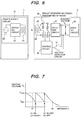
- Fig. 4 shows a schematic view showing the form of the first embodiment of the power transmission control system by radio according to the present invention.
- the power supply circuit 21 provided in the reader and/or writer 1 has the same constitution as that shown in Fig. 2.
- An induced voltage generator portion 28a is composed of the coil 26 and the rectifier 27 shown in Fig.
- variable impedance circuit 30 which supplies a controlled high frequency power to the rectifier circuit 27 in controlling the high frequency power obtained from the coil 26 by varying its impedance
- a voltage detector circuit 31 which detects the induced voltage VL obtained from the rectifier circuit 27, and a control circuit 32 which controls the variable impedance circuit 30 by varying its impedance based on the induced voltage detected in the induced voltage detector circuit 31.
- the internal circuit 29 in the IC card 2 is the same as that shown in Fig. 2.
- the voltage detector circuit 31, as shown by a chain line can be a circuit which calculates the mean value of induced voltages by detecting a high frequency power (a high frequency voltage) obtained from the variable impedance circuit 30, for example.
- the voltage detector circuit detects the induced voltage VL obtained from the reifier circuit 27 and when it detects a voltage which deviates out of the allowable induced voltage range Vmin to Vmax, the impedance of the variable impedance circuit 30 is controlled by the control circuit 32, and the high frequency power obtained from the coil 26 is supplied to the rectifier circuit 27 being controlled to be a proper value; thereby, a voltage which is constantly kept in the allowable induced voltage range can be obtained from the rectifier circuit 27.
- the voltage detector circuit detects the induced voltage VL obtained from the reifier circuit 27 and when it detects a voltage which deviates out of the allowable induced voltage range Vmin to Vmax, the impedance of the variable impedance circuit 30 is controlled by the control circuit 32, and the high frequency power obtained from the coil 26 is supplied to the rectifier circuit 27 being controlled to be a proper value; thereby, a voltage which is constantly kept in the allowable induced voltage range can be obtained from the rectifier circuit 27.
- Fig. 5 shows a schematic view of the second embodiment of the power transmission control system according to the present invention.
- a different point from the first embodiment shown in Fig. 4 is in that the variable impedance circuit 30 is provided following the rectifier circuit 27.
- the constitution of the power supply circuit 21 provided in the reader and/or writer is the same as that shown in Fig. 2.
- the induced voltage generator portion 28a in the IC card 2 is composed of a rectifier circuit 27 which converts the high frequency power obtained from the coil 26 into a DC voltage VL, a voltage detector circuit 31 which detects the DC voltage VL obtained from the rectifier circuit 27, a variable impedance circuit 30 which supplies a controlled DC voltage to the internal circuit 29, the controlled DC voltage which is obtained from the DC voltage output from the rectifier circuit 27 being controlled by varying its impedance based on the induced voltage detected by the voltage detector circuit 31, and the control circuit 32 which controls the impedance of the variable impedance circuit 30 to vary.
- the internal circuit 29 in the IC card 2 is the same as that shown in Fig. 2.
- the voltage detector circuit 31 detects the rectified induced voltage VL obtained from the rectifier circuit 27 and when it is detected that the voltage deviates out of the allowable induced voltage range, Vmin to Vmax, the impedance of the variable impedance circuit is controlled by the control circuit 32 to correct the deviation, thus a DC voltage obtained from the rectifier circuit 27 is controlled and supplied to the internal circuit 29; thereby, a voltage in the range of allowable induced voltage can be constantly obtained from the rectifier 27. In the result, even when the distance between the reader and/or writer 1 and the IC card 2 approaches 5 cm it is possible to supply a voltage in the allowable range to the internal circuit 29.
- Fig. 6 shows a concrete form of the variable impedance circuit 30 shown in Fig. 4 in the first embodiment.
- the variable impedance circuit there are two circuit elements, an resistor R1 and an electron switch 1 connected in series and an resistor R2 and an electron switch 2 connected in series, and a coil 26 is connected with both above-mentioned circuit elements in parallel, which constitutes the variable impedance circuit 30.
- the ON-OFF operations of these electron switches, S1 and S2 are controlled by control signals from the control circuit 32.
- control circuit 32 As shown in Fig.
- the electron switch S2 is made ON in the state where the electron switch S1 is kept ON, then both resistors R1 and R2 are connected and the rectified induced voltage VL is lowered to the Vmin; therefore, even when the distance between the coil 26 of the IC card and the coil 24 of the power supply circuit is decreased to d1, it will be possible to keep the voltage VL not to exceed the Vmax.
- the allowable range between the Vmin and Vmax can be made narrower by increasing the number of resistors.
- variable impedance circuit 30 when the variable impedance circuit 30 is constituted with a circuit in which a resistor R1 and an electron switch S1 are connected in series and also a resistor R2 and an electron switch S2 are connected in series, and both circuit elements are connected to the coil 26 in parallel, the variable impedance circuit 30 can be an excellent circuit in responsibility.
- the variable impedance circuit 30 mentioned in the above can be applied to the variable impedance circuit 30 composed of a variable resistor element shown in Fig. 5.
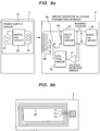
- a variable impedance circuit 30 is provided next to a constant voltage power supply circuit 204 which is provided following a rectifier circuit 27 (203), which makes it possible to miniaturize the elements in the pressure protection circuit 30. Owing to it, a wireless chip 202 can be constituted small and in the result, it is made possible to cut down the cost of the IC card, not only that of the chip.
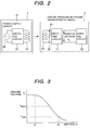
- Fig. 8(a) shows a concrete form of the variable impedance circuit 30 shown in Fig. 4 in the second embodiment 2.
- the variable impedance circuit 30 is constituted with the circuit elements as described below: 2 circuit elements, a capacitor C1 and an electron switch S1 being connected in series, and a capacitor C2 and an electron switch S2 being connected in series, are connected to the coil 26 in parallel. These electron switches, S1 and S2, are ON-OFF controlled by a control signal from the control circuit 32.
- Fig 9 shows a concrete form of the variable impedance circuit 30 shown in Fig. 4 in a third embodiment.
- the variable impedance circuit 30 is constituted as shown in the following: terminals, T1, T2 and T3 are formed corresponding the length of the coil 26 and an electron switch St which is able to change over the connection to T1, T2 or T3 is provided, the switch St which can be changed over by a control signal from the control circuit 32.
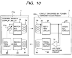
- Fig. 10 shows a schematic view of a power transmission control system by radio in a third embodiment according to the present invention.
- the power supply circuit 21 provided in the reader and/or writer 1 comprises: a control power supply 22a which generates a high frequency voltage of 13.56 MHz of a variable voltage, a matching circuit 23 for impedance matching, a coil 24 for transmitting a radio wave of 13.56 MHz in a power level of approximately 2 to 5 W, a receiving coil (coil-shaped, or spiral-shaped antenna) 37 and a receiving circuit 38 for receiving a radio signal concerning an induced voltage transmitted from the IC card 2, and a control circuit 39 which controls the high frequency voltage output from the control power supply 22a based on the induced voltage value received in the receiving circuit 38.
- the induced voltage generator portion 28b on the IC card 2 is composed of a coil 26, a rectifier circuit 27 shown in Fig. 2 and the circuits as shown in the following: a voltage detector circuit 31 which detects a rectified induced voltage VL obtained from the rectifier circuit 27, a transmitting circuit 35 for transmitting a signal concerning the value of an induced voltage detected in the voltage detector circuit 31 to the coil 37 of the power supply circuit 21a by a radio wave, and a coil (coil-shaped or spiral-shaped antenna) 36.
- the internal circuit 29 on the IC card 2 is the same as that shown in Fig. 2.
- the voltage detector circuit 31 detects a rectified induced voltage VL obtained from the rectifier circuit 27, a signal concerning the detected induced voltage value is transmitted to the coil 37 of the power supply circuit 21a by the transmitting circuit 35 and the coil 36 by radio to be received by the coil 37 and receiving circuit 38.
- the control circuit 39 detects the deviation of the rectified induced voltage VL out of the allowable range of the rectified induced voltage value, from Vmin to Vmax, base on the signal of the rectified induced voltage value received in the receiving circuit 38 and controls the high frequency voltage of the control power supply 22a, and the controlled high frequency power transmitted from the coil 24 to the coil 26 is supplied to the rectifier circuit 27; therefore, a voltage with a value in the range of allowable induced voltage value can be constantly obtained from the rectifier circuit 27. In the result, even when the distance between the reader and/or writer 1 and the IC card 2 approaches to the order of 5 cm, it is possible to supply a voltage in the allowable range to the internal circuit 29.
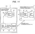
- Fig. 11 shows a schematic view of a fifth embodiment of the power transmission control system by radio according to the present invention.
- the power supply circuit 21b provided in the reader and/or writer 1 comprises: a control power supply 22a which generates a high frequency variable voltage of 13.56 MHz, a matching circuit 23 for impedance matching, a coil 24 for transmitting high frequency power having the frequency of 13.56 MHz and power level of about 2 to 5 W, a sensor circuit 41 which detects an instantaneous distance from a passing IC card 2 using infrared rays or ultrasonic waves, a position detector circuit 42 which calculates an instantaneous distance (position) from a passing IC card 2 using a signal obtained from the sensor circuit 41, and a control circuit 39 which controls the high frequency voltage of the control power supply 22a based on the information of an instantaneous distance d (position) from an passing IC card 2 detected
- the sensor circuit 41 detects the instantaneous distance from a passing IC card 2 using infrared rays or ultrasonic waves, with the detected signal
- the position detector circuit 42 calculates an instantaneous distance (position) from the passing IC card 2
- the control circuit 39 calculates a high frequency voltage value to be generated from the control power supply 22a from the relation between the distance d and the rectified induced voltage VL shown in Fig.
- Fig. 12 shows a schematic view of a first embodiment concerning the whole system including the part in which the information concerning railway tickets or commutation tickets is communicated by radio and an IC card performs the role of a railway tickets or commutation ticket.
- the reader and/or writer 1 comprises, besides the power supply circuit 21, an information transmitter-receiver portion 51 which communicates with the IC card 2 about the information by radio.
- the information transmitter-receiver portion 51 is connected to a communication network and a mechanism to open or close a wicket door or a display device, and outputs data to be transmitted to the IC card 2 to a modulator portion 54 and is composed of the following: a CPU 52 which processes data obtained from a demodulator portion 55 and outputs them, a memory 53 which stores data or processing program data obtained from the IC card 2, a modulator portion 54 which modulates the data from the CPU 52 with 3.39 MHz to transmit the data to the IC card 2, an amplifier 56 which amplifies the modulated data in the modulator portion 54, a coil 59 which exchanges data by radio with the IC card 2, an amplifier 57 which amplifies the data received by the coil 59, a demodulator portion 55 to demodulate the signal amplified in the amplifier 57 with 3.39 MHz, and
- the IC card 2 comprises an induced voltage generator portion 28 and an internal circuit 29, and the internal circuit 29 is composed of the following: a memory 63 which stores data concerning railway tickets, commutation tickets, etc., a CPU 62 which controls the memory 63 concerning read, write, etc., a modulator portion 65 which modulates the data read from the memory 63 with a signal of 3.39 MHz, an amplifier 67 which amplifies the signal from the modulator portion 65, a coil 69 which exchanges data by radio with the coil 59 of the data receiving and transmitting portion 51, an amplifier 66 which amplifies the data received by the coil 69, a demodulator portion 64 which demodulates the signal amplified in the amplifier 66 with 3.39 MHz, and a matching circuit 68 for impedance matching.
- a memory 63 which stores data concerning railway tickets, commutation tickets, etc.
- a CPU 62 which controls the memory 63 concerning read, write, etc.
- a modulator portion 65 which modulates the data read from the
- an IC card 2 functions as a railway ticket or a commutation ticket.
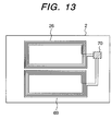
- Fig. 13 shows the state of one or two circuit chips 70 mounted with parts such as the coil 26, the coil 69, and other circuits, 28, 27, 29, and 32, being connected to the coil 26 and the coil 69.
- the length of the coil 26 will be lengthened by increasing number of turns and taps, T1, T2 and T3 will be provided to input to the circuit chip 70.
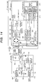
- Fig. 14 shows a schematic view of an embodiment concerning the whole including a part where an IC card functions the role of a railway ticket, commutation ticket, or the like in exchanging data concerning railway tickets, commutation tickets, etc. with a reader and/or writer by radio.
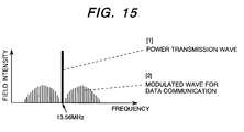
- the second embodiment shown in Fig. 14 shows the case where both transmission of power and communication are performed using a radio wave being composed of a power transmission wave and data communication modulated wave as shown in Fig. 15 between a R/W coil (coil-shaped or spiral-shaped R/W antenna) 101 provided on the R/W unit 1 and a card coil (coil-shaped or spiral-shaped card antenna)201 provided on an IC card 2.
- the power transmission wave and the signal wave have different frequency components seen from a frequency region, but seen from a time region only the amplitude of the power transmission wave varies corresponding to the signal speed.
- the modulated wave of the power transmission wave multiplied by the signal wave is seen as if only the amplitude is varied up and down.
- the modulated wave When the modulated wave is transmitted by radio, it can be considered to use separate antennas respectively, but in the present invention, in order to simplify the noncontact card 2 (proximity radio card, IC card), the field intensity is limited to be within the range decided by the Wireless Conducty Act (500 ⁇ V at a distance of 3m) and a single antenna (R/W coil) is used to transmit the modulated wave.
- the noncontact card 2 proximity radio card, IC card
- the R/W (reader and/or writer) unit 1 comprises the following: a power supply 105 which generates a high frequency voltage of 13.56 MHz, an encoder circuit 107 which encodes input data 106 to be transmitted to a proximity radio card 2, a modulator 108 which superimposes a voltage being amplitude modulated (amplitude shift keying modulation) by a signal encoded in the encoder circuit 107 upon a high frequency voltage of 13.56 MHz generated in the power supply 105, a transmitting amplifier 109 which amplifies a signal ASK-modulated and superimposed upon the high frequency voltage of 13.56 MHz in the modulator 108, an impedance matching circuit (feeding circuit) 102 having a capacitor 104 and being coupled with a signal amplified in the transmitting amplifier 109 through an inductance coupling 103, a R/W coil 101 which generates a radio wave to transmit power and data corresponding to the output of the matching circuit 102 and receives data transmitted from the card coil 201 of the proximity radio card 2 by
- a proximity radio card (noncontact card, IC card) 2 comprises a card coil 201, radio chip 202 and a CPU+ interface chip 210.
- the radio chip 202 and the CPU+ interface chip 210 can be constituted with one chip by miniaturizing the radio chip 202.
- the card coil 201 receives a radio wave generated to perform transmission of power and data from the R/W coil 101 in the R/W unit 1, and generates a radio wave corresponding to the transmitting data which is processed by load-switching modulation.
- the radio chip 202 comprises: an impedance matching and rectifier circuit 203 which functions as a rectifier for the power signal of 13.56 MHz received by the card coil 201 and also functions as a matching circuit for the transmitting and receiving signal, a constant voltage power supply circuit 204 which supplies a constant DC voltage 205 of about 2 to 5 V at a power level of about 5 mW obtained from a rectified induced voltage output from the matching and rectifier circuit 203, a voltage detector circuit 31 which detects the comparison data between the DC voltage VL obtained from the matching and rectifier circuit 203 and a standard (reference) voltage, a variable impedance control circuit 30 being composed of variable resistor elements such as FET which supplies DC power to the IC chips, 202 and 210, as a DC power supply voltage 205 in controlling the DC voltage output from the constant voltage power supply circuit 204 in varying its impedance based on the DC voltage detected in the voltage detector circuit 31, a clock signal extracting circuit 206 which extracts a clock signal from a receiving signal obtained from the
- the CPU+interface chip 210 is composed of a frequency divider circuit 211 which generates a signal for operating the microcomputer 214 in dividing the frequency of a clock signal extracted by the clock signal extracting circuit 206 of the radio chip 202, a decoder circuit 212 which decodes a signal obtained from the waveform shaping circuit 208 of the radio chip 202, a receiving data control circuit 213 which controls decoded data (receiving data) obtained from the decoder circuit 212 and inputs the data to the microcomputer 214, a transmitting data control circuit 215 which obtains data from the microcomputer 214 in controlling the transmitting data, an encoder circuit 216 which encodes transmitting data obtained from the transmitting data control circuit 215 in controlling them and inputs the data to the load switching modulator circuit 209 of the radio chip 202, and a microcomputer 214 of H8, etc.
- the CPU+interface chip 210 will be supplied with a stable power supply voltage 205 from the constant voltage power supply circuit 204 on the radio chip 202.
- the purpose of using the R/W coil 101 and the card coil 201 for transmitting power by a radio wave is to upgrade the efficiency of power transmission in a short range.
- the coil 201 is formed on the proximity radio card, it helps the card to be strong against deformation.
- Both R/W coil 101 and card coil 201 can be formed with spiral antennas.
- a resonance circuit is formed in the card coil 201 in connecting a tuning capacitor to it.
- the card coil 201 is formed to have a multilayered structure of more than 2 layers, which can be formed by winding a spiral-shaped antenna coil consecutively in the same direction, the inductance of the coil and the stray capacity among the windings may constitute a resonance circuit.
- a tuning capacitor 25 may not be needed or an extremely small one will do the work.
- the elements in the pressure protection circuit can be miniaturized by providing a variable impedance circuit 30 composed of variable resistor elements after the constant voltage power supply circuit provided following the rectifier circuit 203, in the result, the radio chip 202 can be formed small and the cost of not only the chip but also that of the IC card can be decreased, moreover the temperature rise in the variable impedance circuit 30 composed of variable resistor elements can be decreased, which will upgrade the reliability of the chip 220.
- a proximity radio card system power can be transmitted by radio, and further information communication by radio can be performed between the reader and/or writer 1 and the noncontact card 2 when the noncontact card (proximity radio card , IC card) 2 is made to approach the reader and/or writer 1.
- a power transmission wave or communication wave is radiated by a coil or a spiral antenna 101 in a reader and/or writer, and the radio wave is received by a coil or a spiral antenna 201 on the side of a card; thereupon, a voltage is induced which operates the circuits on the side of the card and signals are detected.
- an IC card can be constituted with an antenna for receiving a radio wave and the elements of one chip, which allows to realize a low cost IC card.
- a power transmission system by radio and an IC card can be realized, wherein the IC card is arranged to be able to perform transmission of power by radio for the reader and/or writer using a coil-shaped or spiral-shaped antenna coil, and power can be stably supplied by radio from a reader and/or writer device (power transmitting device) to the internal circuit on the IC card by only making the IC card pass the reader and/or writer device (power transmitting device) with noncontact or in proximity to it in miniaturizing the elements in the pressure protection circuit, decreasing the temperature rise in the variable impedance circuit, and improving the responsibility of the system.
- a reader and/or writer device power transmitting device
- a power transmission system by radio, an IC card, and an information communication system using the IC card can be realized, wherein even though the distance between the IC card and the reader and/or writer may largely vary, power can be supplied stably to the IC card in decreasing the temperature rise in the variable impedance circuit by controlling the induced power received on the IC card side varying the static capacity in the circuit
- a proper power can be transmitted from the power transmission portion of the reader and/or writer to the IC card by radio by only passing the IC card through the reader and/or writer with noncontact or in proximity to it; thereby, a DC voltage can be stably supplied to the internal circuit of the IC card and information communication can be performed with high reliability between the reader and/or writer and the IC card.
- an information communication system using an IC card can be realized in which information communication can be performed with high reliability between the reader and/or writer device and the IC card in supplying a stabilized power from the reader and/or writer device to the IC card with noncontact.
Abstract
The present invention comprises a power transmission system, an IC card, and an information communication system using an IC card.
In the power transmission system, power is transmitted by radio from the power transmission device to the IC card. In the IC card, the transmitted induced power is converted into a DC voltage, the transmitted induced power or a voltage corresponding to the induced power is detected, and a desired DC voltage to be supplied to the internal circuit is obtained in controlling impedance based on the detected induced power or the voltage corresponding to the induced power.
Description
- The present invention relates to a power transmission system, an IC card and an information communication system using an IC card, wherein commutation tickets, railway tickets, bus tickets, etc. to be used at wickets in railway stations or on buses will be replaced with IC cards, and when an IC card is made to pass a reader/writer, being provided at a wicket in a railway station or on a bus, with noncontact or in close proximity to it, power can be transmitted from the reader/writer to the IC card by radio.
- It has been known that power can be supplied to an IC card from a power supply side by a noncontact method using rays of light or magnetic fields.
- When commutation tickets, railway tickets, bus tickets, etc. to be used at wickets in railway stations or on buses will be replaced with IC cards, and when a user passes an IC card through a reader/writer provided at a wicket in a railway station or on a bus with noncontact, the distance between the IC card and the reader/writer may vary much. When the reader/writer is so adjusted that proper power can be transmitted from the reader/writer to the IC card when the distance between the IC card and the reader/writer is comparatively large, then in a case where the distance between the reader/writer and the IC card is small, excessive power may be transmitted from the reader/writer to the IC card, which may cause a malfunction or breakage of the IC card.
- In other words, in the prior art, careful consideration was not given to a point that proper power shall be stably transmitted to an IC card from a reader/writer even though the distance between the IC card and the reader/writer may be largely varied.
- Prior art in which it is intended to stably supply power from a reader/writer to an IC card even if the distance between the IC card and the reader/writer is largely varied is explained in Japanese Patents Laid-open No. Hei 7-85233 and Laid-open No. 9-62816.
- In the Japanese Patent Laid-open No. 7-85233, following are described: among noncontact type data carriers of electromagnetic coupling system, in the case of movable equipment having a function to be able to receive data including a control signal from fixed equipment, a rectifier circuit composed of a rectifier D1 and a capacitor C2, and a variable resistor element composed of a transistor T2, resistor R3 and resistor R4 being controlled by a DC voltage obtained from the rectifier circuit are connected to a receiving coil of the data carrier in parallel, and an excess power will be consumed in the variable resistor elements. Further it is described in the Japanese Patent Laid-open No. Hei 7-85233 that a signal detector circuit composed of a rectifier D2, a resistor R1 and a capacitor C3 which detects an amplitude-modulated wave superimposed on a AC voltage induced in the receiving coil and transmits the detected data to a main circuit of the data carrier as an input signal, and an amplitude modulator circuit which receives the output signal of the main circuit of the data carrier for switching a transistor T1, and being composed of the transistor T1 which transmits data from the data carrier to the fixed equipment, a capacitor C4 and a resistor R2 are connected to the receiving coil of the data carrier in parallel. In the prior art as mentioned in the above, a resonant circuit is not formed in the receiving coil of the data carrier, so that in a case where the distance between the transmitting coil on the fixed side and the receiving coil on the data carrier side is large, an enough voltage is not induced in the receiving coil and it is made difficult to obtain the power required by the main circuit of the data carrier. There is also another problem in the prior art. Since a half-wave rectifier is adopted in the prior art, a large ripple is produced, which requires a large smoothing capacity; therefore, it is made difficult to incorporate a capacitor of a large capacity in a data carrier in miniaturizing it.
- It is described in the Japanese Patent Laid-open No. Hei 9-62816 that a receiving signal level of a resonance circuit of an antenna for transmitting and receiving data is detected and the quality factor Q of the antenna resonance circuit is varied by changing the variable resistor element according to the detected voltage in order to adjust a receiving signal level to a desirable value.
- In these prior art, since a variable resistor element is directly connected to a receiving antenna in parallel, there is a problem in that the temperature rise in the variable resistor element is large and the size of a pressure protection circuit becomes large.
- The purpose of the present invention is to solve the above-mentioned problems and offer an IC card and a power transmission system by radio in which it is made possible to stably supply power by radio from a reader/writer to the internal circuit of an IC card in miniaturizing the elements of a pressure protection circuit and decreasing the temperature rise in a variable impedance circuit provided in an IC card even though the distance between the IC card and the reader/writer may be largely varied.
- Another object of the present invention is to offer an IC card and a power transmission system by radio in which the power can be stably supplied to the internal circuit of the IC card by radio from a reader and/or writer by only making the IC card pass the reader and/or writer with noncontact or in close proximity to it by improving the responsibility of the system in miniaturizing the elements in a pressure protection circuit and decreasing the temperature rise in a variable impedance circuit.
- A further object of the present invention is to offer an IC card and an information communication system using an IC card in which it is made possible to supply power stably from a reader and/or writer to the IC card with noncontact in miniaturizing the elements in the pressure protection circuit and decreasing the temperature rise in the variable impedance circuit provided in the IC card and to perform information communication with high reliability between the reader and/or writer and the IC card.
- Yet another object of the present invention is to offer a power transmission system by radio, an IC card and an information communication system using the IC card. In the power transmission system by radio it is so arranged that power can be stably supplied even when the distance between an IC card and a reader/writer is largely varied in decreasing the temperature rise in the variable impedance circuit by controlling the static capacity for the induced power received on the IC card side.
- A still further object of the present invention is to offer a power transmission system by radio, an IC card and an information communication system using the IC card. In the power transmission system by radio it is so arranged that proper power can be stably supplied to the IC card by radio from the power transmission portion of the reader/writer by only passing the IC card through the reader/writer with noncontact or in proximity to it and information can be communicated between the reader/writer and the IC card with high reliability.
- In order to achieve the above-mentioned objects, the present invention is a power transmission system in which power is transmitted by radio from a power transmitting device (reader and/or writer device) to an IC card. The IC card comprises: an antenna having a resonance circuit for receiving the transmitted radio wave, a full wave rectifier circuit for rectifying an induced power received by the antenna, a power supply circuit which converts a DC voltage output from the full wave rectifier circuit into a power supply voltage, a detector circuit which detects the DC voltage output from the full wave rectifier circuit, an impedance control circuit portion which produces a desired power supply voltage from the DC voltage detected in the detector circuit by controlling the impedance of the circuit, and an internal circuit to be supplied with the desired power supply voltage obtained from the impedance control circuit.
- The present invention is also a power transmission system in which power is transmitted by radio from a power transmission device to an IC card, wherein the IC card comprises: a receiving portion which receives the transmitted radio wave and produces induced power, a rectifier circuit portion which converts the induced power in the receiving portion into a DC voltage, a variable impedance circuit portion in which the DC voltage obtained in the rectifier circuit is controlled by varying the impedance of the circuit based on the induced power detected in the detector circuit portion or a voltage corresponding to the induced power, and an internal circuit to be supplied with a controlled DC voltage from the variable impedance control circuit.
- The present invention is also a power transmission system in which power is transmitted by radio from the power transmission device to an IC card. In the IC card, the transmitted induced power is converted into a DC voltage, the transmitted induced power or a voltage corresponding to the induced power is detected, and a power supply voltage of a desired DC voltage to be supplied to the internal circuit is obtained by controlling a static capacity based on the detected induced power or a voltage corresponding to the induced power.
- The present invention is a power transmission system in which power is transmitted by radio from a power transmission device to an IC card. The IC card comprises: a rectifier circuit which converts the transmitted induced power into a DC voltage, an internal circuit to be supplied with the DC voltage obtained from the rectifier circuit, a detector circuit which detects the transmitted induced power or a voltage corresponding to the induced power, and a static capacity control circuit which obtains a power supply voltage of a desired DC voltage to be supplied to the internal circuit by controlling the static capacity based on the induced voltage or a voltage corresponding to the induced power which is detected in the detector circuit.
- The present invention is a power transmission system in which power is transmitted by radio from a power transmitting device to an IC card. The IC card comprises the functions as shown below: the transmitted induced power is converted into a DC voltage to be supplied to an internal circuit, the transmitted induced power or a voltage corresponding to the induced power is detected, and the information about the detected induced power or a voltage corresponding to the induced power is transmitted by radio to the power transmitting device. The power transmitted from the power transmitting device is controlled based on the above-mentioned transmitted information.
- The present invention is a power transmission system in which power is transmitted by radio from a power transmitting device to an IC card. The IC card comprises the function to convert the transmitted induced power into a DC voltage and to supply the DC voltage to the internal circuit, and also to detect the information concerning the relative position of the IC card to that of the power transmitting device. The power transmitted from the power transmission device is controlled based on the above-mentioned detected information.
- The present invention is a power transmission system in which power is transmitted by radio from a power transmitting device to an IC card. The IC card comprises the function to convert the transmitted induced power into a DC voltage and to supply the DC voltage to the internal circuit and to detect the information concerning the relative position of the IC card to that of the power transmitting device. A desired DC voltage can be obtained in controlling the impedance of a circuit in the IC card based on the detected information.
- The present invention is an IC card which comprises: an antenna having a resonance circuit for receiving a transmitted radio wave, a full wave rectifier circuit for rectifying an induced power received with the antenna, a power supply circuit for converting the DC voltage obtained from the full wave rectifier circuit into a power supply voltage, a detector circuit for detecting the DC voltage rectified in the full wave rectifier circuit, an impedance control circuit which controls the impedance of the circuit for making the detected DC voltage a desired DC voltage and making the power supply voltage converted in the power supply circuit a desired power supply voltage, and an internal circuit to be supplied with the desired power supply voltage obtained from the impedance control circuit portion.
- The present invention is an IC card which comprises: a receiver portion which receives a radio wave to produce an induced power, a rectifier circuit portion for rectifying the induced power generated in the receiver portion to convert the induced power to a DC voltage, a detector circuit portion which detects an induced power obtained in the receiver portion or a voltage corresponding to the induced power, a variable impedance control circuit portion which controls the DC voltage obtained from the rectifier circuit portion based on the induced power detected in the detector circuit portion or a voltage corresponding to the induced power, and an internal circuit to be supplied with a controlled DC voltage from the variable impedance control circuit portion.
- The present invention comprises an IC card in which an impedance in the variable impedance circuit portion is formed with a resistor.
- The present invention is an IC card in which the full wave rectifier circuit, the power supply circuit, the detector circuit, the impedance control circuit, and the internal circuit are composed with one chip.
- The present invention is an IC card which comprises: a receiver portion which receives an induced power by radio, a rectifier circuit portion which rectifies the induced power received in the receiver portion to convert it into a DC voltage, a detector circuit portion which detects the induced power obtained from the receiver portion or a voltage corresponding to the induced power, a static capacity control circuit portion which obtains a desired DC voltage from the rectifier circuit portion by controlling the static capacity based on the induced power detected in the detector circuit portion or a voltage corresponding to the induced power, and an internal circuit which is supplied with a DC voltage from the rectifier circuit portion being controlled by the static capacity control circuit portion.
- The present invention is an information communication system using an IC card which comprises a reader and/or writer device (unit) having an information communication portion and a power transmitting portion and power is transmitted by radio from the power transmitting portion to an IC card.
- The IC card comprises: a rectifier circuit portion which rectifies the induced power transmitted from the reader and/or writer to convert the induced power into a DC voltage, a detector circuit portion which detects the induced power obtained from the receiver portion or a voltage corresponding to the induced power, a variable impedance control circuit portion which controls the impedance of the circuit according to the DC voltage obtained from the rectifier circuit portion based on the induced power detected in the detector circuit portion or a voltage corresponding to the induced power, and an internal circuit which obtains a desired DC voltage from the variable impedance control circuit. The information communication system is so designed that an information communication can be performed using a radio wave between the internal circuit of the IC card and the information communication portion of the reader and/or writer device.
- transmitted to the IC card or a voltage corresponding to the induced power is detected, and a desired DC voltage is obtained in controlling the impedance base on the detected induced power or a voltage corresponding to the induced power and the desired DC voltage is supplied to the internal circuit. The present invention is so constituted that it is possible to perform information communication by radio between the internal circuit of the IC card and the information communication portion of the reader and/or writer device.
- The present invention is an information communication system using an IC card, which comprises reader and/or writer device having an information communication portion and a power transmission portion and power is transmitted by radio from the power transmitter portion to the IC card by radio. The IC card comprises: an antenna having a resonance circuit for receiving a radio wave transmitted from the reader and/or writer device, a full wave rectifier circuit for rectifying the induced power received in the antenna, a power supply circuit which converts the DC voltage rectified in the full wave rectifier circuit into a power supply voltage, a detector circuit which detects the DC voltage rectified in the full wave rectifier circuit, an impedance control circuit which controls the impedance of the circuit to make a detected DC voltage detected in the detector circuit a desired DC voltage and to make the power supply voltage converted in the power supply circuit a desired power supply voltage, and an internal circuit to be supplied with the desired power supply voltage obtained from the impedance control circuit.
- The information communication system is so designed that the information communication can be performed by a radio wave between the internal circuit of the IC card and the information communication portion of the reader and/or writer device.
- The present invention is an information communication system using an IC card which comprises a reader and/or writer device having an information communication portion and a power transmission portion which transmits power from the power transmission portion to the IC card by radio. In the IC card, following operations are performed: the induced power transmitted from the reader and/or writer device is converted into a DC voltage and it is supplied to the internal circuit, the induced power transmitted to the IC card or a voltage corresponding to the induced power is detected, and the information concerning the detected induced power or the voltage corresponding to the induced power is transmitted to the power transmission portion of the reader and/or writer device by radio. The reader and/or writer controls the power to be transmitted from the power transmission portion based on the information sent from the IC card. The information communication system is so designed that information communication can be performed between the internal circuit of the IC card and the information communication portion of the reader and/or writer device.
- The present invention is an information communication system using an IC card, wherein the transmission of power by radio from the reader and/or writer to the IC card and the communication of information by radio between the internal circuit of the IC card and the information communication portion of the reader and/or writer device are performed with a common antenna.
- The present invention is an information communication system, using an IC card, wherein the reader and/or writer device comprises: a power supply portion which generates a signal to be used for the transmission of power, an encoder circuit for encoding input data for transmission, a modulator which executes amplitude modulation of a signal obtained from the encoder circuit and superimposes it on the signal obtained from the power supply portion, a feeder circuit for feeding power based on the signal obtained from the modulator, and an antenna for generating a radio wave corresponding to the fed current by the feeder circuit.
- The present invention is an information communication system using an IC card, wherein the internal circuit of the IC card comprises: a decoder circuit which performs waveform shaping and decodes a modulated wave for communication detected by the antenna, a microcomputer which inputs received data decoded in the decoder circuit and outputs transmission data, an encoder circuit which encodes the transmitting data output from the microcomputer, and a modulator which modulates a signal and inputs it to the antenna based on the signal encoded in the encoder circuit.
- As explained in the above, according to the above-mentioned constitution, it is made possible to realize a power transmission system by radio and an IC card, wherein even though the distance between the IC card and the reader and/or writer device (power transmitting device) is largely varied, power can be stably transmitted by radio from the reader and/or writer device to the internal circuit of the IC card in miniaturizing a pressure protection circuit provided in the IC card and decreasing the temperature rise in a variable impedance circuit. In particular, the realization of miniaturization of the elements of the pressure protection circuit and the low temperature rise in the variable impedance circuit made it possible to constitute an IC card with an antenna for receiving a radio wave and elements of one-chip constitution, which caused to realize a low cost IC card.
- According to the above-mentioned constitution, a power transmission system by radio and an IC card can be realized, wherein power can be transmitted from the reader and/or writer device to the IC card by radio using a coil-shaped antenna or a spiral antenna on the IC card, and power can be supplied stably by radio from the reader and/or writer device to the internal circuit of the IC card by only making an IC card pass the reader and/or writer device with noncontact or in the proximity to it in miniaturizing the elements in the pressure protection circuit, decreasing the temperature rise in the variable impedance circuit, and improving the responsibility of the circuit.
- According to the above-mentioned constitution, a power transmission system by radio, an IC card, and an information communication system using an IC card can be realized, wherein power can be stably supplied to the IC card even though the distance between the IC card and the reader and/or writer is largely varied in decreasing the temperature rise in the variable impedance circuit by controlling the induced power received on the side of the IC card by varying the static capacity in the variable impedance circuit.
- According to the above-mentioned constitution, a power transmission system by radio, an IC card, and an information communication system using the IC card can be realized, wherein proper power can be transmitted from the power transmission portion of the reader and/or writer device to the IC card by radio by only making the IC card pass the reader and/or writer with noncontact or in proximity to it. Thus, power is stably supplied to the internal circuit of the IC card, and the communication of information of high reliability can be performed between the reader and/or writer device and the IC card.
- According to the above-mentioned constitution, an information communication system using an IC card can be realized, wherein power is stably supplied from the reader and/or writer to the IC card with noncontact, and the communication (transmission and reception) of information of high reliability can be performed between the reader and/or writer device and the IC card.
-
- Fig. 1 shows a schematic of a power transmission system according to the present invention, in which power is transmitted by radio from a reader and/or writer device provided at a wicket in a railway station or on a bus to an IC card which is passed the reader and/or writer device with noncontact or in proximity to it;
- Fig, 2 shows a power transmission system by radio according to the present invention;
- Fig. 3 shows the relation between d and VL, where d denotes the distance between a coil of a power supply circuit provided in a reader and/or writer and an IC card, and VL denotes an induced voltage VL obtained from an rectifier circuit;
- Fig. 4 shows a schematic of a first embodiment of the power transmission system by radio according to the present invention;
- Fig, 5 shows a schematic of a second embodiment of a power transmission system by radio according to the present invention;
- Fig. 6 shows a concrete form of the
variable impedance circuit 30 shown in Fig. 4 in the first embodiment; - Fig. 7 shows a state where an induced voltage is controlled within an allowable range owing to impedance control;
- Figs. 8(a) and 8(b) show a concrete form of the
variable impedance circuit 30 shown in Fig. 4 in the second embodiment; - Figs. 9(a) and 8(b) show a concrete form of the
variable impedance circuit 30 shown in Fig. 4 in a third embodiment; - Fig. 10 shows a schematic view of a power transmission control system by radio in the third embodiment according to the present invention;
- Fig. 11 shows a schematic view of a power transmission control system by radio in a fourth embodiment according to the present invention;
- Fig. 12 shows a schematic view of the whole of the present invention including the part in which an IC card functions the roles of railway tickets, commutation tickets, etc. in transmitting or receiving the information concerning railway tickets, commutation tickets, etc. by radio in the first embodiment;
- Fig. 13 shows a plan view showing the mounted state of elements on an IC card according to the present invention;
- Fig. 14 shows a schematic view of the whole of the present invention including the part in which an IC card functions the roles of railway tickets, commutation tickets, etc. in transmitting or receiving the information concerning railway tickets, commutation tickets, etc. by radio in the second embodiment; and
- Fig. 15 shows the relation between the power transmitting wave and the modulated wave for the data communication according to the present invention.
- In the following, the forms of embodiments of a power transmission system by radio and an IC card according to the present invention will be explained referring to the drawings.
- Fig. 1 is a schematic view of a power transmission system according to the present invention in which power is transmitted by radio from a reader and/or
writer 1 provided at a wicket in a railway station or on a bus to anIC card 2 which is to be passed the reader and/orwriter 1 with noncontact or in proximity to it. TheIC card 2 is passed the reader and/orwriter 1 provided at the wicket in a railway station or on a bus by an user with noncontact, at a distance of about 5 to 20 cm. In that case, the information concerning railway tickets, commutation tickets, etc. is communicated by radio between the reader and/or writer and the IC card; thereby, the IC card will be able to perform the role of a railway ticket, commutation ticket, or the like. - Fig. 2 shows a schematic view of a power transmission system by radio according to the present invention. A
reference numeral 21 denotes a power supply circuit in the reader and/orwriter 1 provided at a wicket in a railway station or on a bus. Thepower supply circuit 21 comprises: apower supply 22 which generates a high frequency voltage of 13.56 MHz, animpedance matching circuit 23 which prevents reflection at a junction point, and acoil 24 which transmits power of about 2 to 5 W of 13.56 MHz by radio. The IC card comprises an inducedvoltage generator portion 28 which is composed of acoil 26 which receives power by radio from thepower supply circuit 21 provided in the reader and/or writer and arectifier circuit 27 which converts the high frequency power received by thecoil 26 into a DC voltage of the order of 7 to 15 V, and an internal circuit 29 (constituted with an IC chip, for example) which is operated with a DC voltage of the order of 7 to 10 V generated in the inducedvoltage generator portion 28. - In order to be able to supply a desired DC voltage to the
internal circuit 29, even though the distance between theIC card 2 and the reader and/orwriter 1 may be extremely large, a resonance circuit with a tuningcapacitor 25 is provided in thecoil 26 to be able to obtain a large induced voltage. Thecoil 26 has a multilayer structure of more than 2 layers in which a spiral-shaped antenna coil is wound continuously in the same direction, so that stray capacitance between windings and the inductance of the coil may constitute a resonance circuit. As a result, a tuningcapacitor 25 may not be needed or an extremely small one will do the work. - In order to transmit power by radio, a coil (a coil-shaped or spiral-shaped antenna) 24 and a coil (a coil-shaped or spiral-shaped antenna) 26 are used for the purpose of improving the responsibility of the system to be able to supplying power to the internal circuit ( constituted with an IC chip, for example) of the
IC card 2 in less than 0.1 sec. It has a merit to improve the strength of theIC card 2 against deformation by forming thecoil 26 on theIC card 2. Therefore, if it is possible to transmit power to theinternal circuit 29 of theIC card 2 in less than 0.1 sec., a light emitting element and a light receiving element can be used in place of thecoils - Fig. 3 shows the relation between d and VL, where d denotes the distance between the
coil 24 of thepower supply circuit 21 provided in a reader and/orwriter 1 and theIC card 25, and VL denotes the induced voltage obtained from therectifier circuit 27. As shown in Fig. 3, in the case where the system is so designed that when the distance d between thecoil 24 of thepower supply circuit 21 and theIC card 25 is at its maximum value d2 of about 20 cm, the allowable minimum voltage Vmin of about 2 to 4 V can be obtained, when the distance d between thecoil 24 of thepower supply circuit 21 is at its minimum value d1 of about 5 cm, the induced voltage VL becomes the order of 40 V which largely exceeds the allowable maximum voltage Vmax which may cause malfunction in theinternal circuit 29 or breakage of it. - Accordingly in the present invention, the induced voltage VL obtained from the
rectifier circuit 27 shall be constantly controlled to be in the allowable range of the induced voltage, from Vmin to Vmax, even when an IC card is passed the reader and/orwriter 1 with noncontact at a distance of about 5 to 20 cm. - In the next step, the form of a first embodiment of a power transmission system by radio according to the present invention will be explained referring to Fig. 4. Fig. 4 shows a schematic view showing the form of the first embodiment of the power transmission control system by radio according to the present invention. The
power supply circuit 21 provided in the reader and/orwriter 1 has the same constitution as that shown in Fig. 2. An inducedvoltage generator portion 28a is composed of thecoil 26 and therectifier 27 shown in Fig. 2 added with the following circuits: avariable impedance circuit 30 which supplies a controlled high frequency power to therectifier circuit 27 in controlling the high frequency power obtained from thecoil 26 by varying its impedance, avoltage detector circuit 31 which detects the induced voltage VL obtained from therectifier circuit 27, and acontrol circuit 32 which controls thevariable impedance circuit 30 by varying its impedance based on the induced voltage detected in the inducedvoltage detector circuit 31. Theinternal circuit 29 in theIC card 2 is the same as that shown in Fig. 2. Thevoltage detector circuit 31, as shown by a chain line, can be a circuit which calculates the mean value of induced voltages by detecting a high frequency power (a high frequency voltage) obtained from thevariable impedance circuit 30, for example. - In an arrangement as shown in the above, the voltage detector circuit detects the induced voltage VL obtained from the
reifier circuit 27 and when it detects a voltage which deviates out of the allowable induced voltage range Vmin to Vmax, the impedance of thevariable impedance circuit 30 is controlled by thecontrol circuit 32, and the high frequency power obtained from thecoil 26 is supplied to therectifier circuit 27 being controlled to be a proper value; thereby, a voltage which is constantly kept in the allowable induced voltage range can be obtained from therectifier circuit 27. In the result, even when the distance between the reader and/orwriter 1 and theIC card 2 approaches 5 cm, it is possible to supply a voltage in the allowable range of the induced voltage to theinternal circuit 29. In the above, it is possible to constitute therectifier circuit 27 and theinternal circuit 29 with one IC chip. - In the next step, a second embodiment of the power transmission control system by radio according to the present invention will be explained referring to Fig. 5. Fig. 5 shows a schematic view of the second embodiment of the power transmission control system according to the present invention. In the second embodiment shown in Fig. 5, a different point from the first embodiment shown in Fig. 4 is in that the
variable impedance circuit 30 is provided following therectifier circuit 27. The constitution of thepower supply circuit 21 provided in the reader and/or writer is the same as that shown in Fig. 2. The inducedvoltage generator portion 28a in theIC card 2 is composed of arectifier circuit 27 which converts the high frequency power obtained from thecoil 26 into a DC voltage VL, avoltage detector circuit 31 which detects the DC voltage VL obtained from therectifier circuit 27, avariable impedance circuit 30 which supplies a controlled DC voltage to theinternal circuit 29, the controlled DC voltage which is obtained from the DC voltage output from therectifier circuit 27 being controlled by varying its impedance based on the induced voltage detected by thevoltage detector circuit 31, and thecontrol circuit 32 which controls the impedance of thevariable impedance circuit 30 to vary. Theinternal circuit 29 in theIC card 2 is the same as that shown in Fig. 2. - In the arrangement as mentioned in the above, the
voltage detector circuit 31 detects the rectified induced voltage VL obtained from therectifier circuit 27 and when it is detected that the voltage deviates out of the allowable induced voltage range, Vmin to Vmax, the impedance of the variable impedance circuit is controlled by thecontrol circuit 32 to correct the deviation, thus a DC voltage obtained from therectifier circuit 27 is controlled and supplied to theinternal circuit 29; thereby, a voltage in the range of allowable induced voltage can be constantly obtained from therectifier 27. In the result, even when the distance between the reader and/orwriter 1 and theIC card 2 approaches 5 cm it is possible to supply a voltage in the allowable range to theinternal circuit 29. - Fig. 6 shows a concrete form of the
variable impedance circuit 30 shown in Fig. 4 in the first embodiment. In the variable impedance circuit, there are two circuit elements, an resistor R1 and anelectron switch 1 connected in series and an resistor R2 and anelectron switch 2 connected in series, and acoil 26 is connected with both above-mentioned circuit elements in parallel, which constitutes thevariable impedance circuit 30. The ON-OFF operations of these electron switches, S1 and S2, are controlled by control signals from thecontrol circuit 32. As shown in Fig. 7, when the distance between thecoil 24 of thepower supply circuit 21 and thecoil 26 of theIC card 2 being denoted by d decreases to a smaller one being off from d2, a large value of d, and the rectified induced voltage VL exceeds Vmax, at first, the electron switch S1 is made ON in the state where the electron switch S2 is kept OFF by a control signal from thecontrol circuit 32, then the resistor R1 is connected and the induced voltage VL is lowered to the Vmim. When thecoil 26 of theIC card 2 further approaches thecoil 24 of the power supply circuit and the induced voltage VL exceeds the Vmax again, the electron switch S2 is made ON in the state where the electron switch S1 is kept ON, then both resistors R1 and R2 are connected and the rectified induced voltage VL is lowered to the Vmin; therefore, even when the distance between thecoil 26 of the IC card and thecoil 24 of the power supply circuit is decreased to d1, it will be possible to keep the voltage VL not to exceed the Vmax. The allowable range between the Vmin and Vmax can be made narrower by increasing the number of resistors. As mentioned in the above, when thevariable impedance circuit 30 is constituted with a circuit in which a resistor R1 and an electron switch S1 are connected in series and also a resistor R2 and an electron switch S2 are connected in series, and both circuit elements are connected to thecoil 26 in parallel, thevariable impedance circuit 30 can be an excellent circuit in responsibility. Thevariable impedance circuit 30 mentioned in the above can be applied to thevariable impedance circuit 30 composed of a variable resistor element shown in Fig. 5. In particular as shown in Fig. 14, avariable impedance circuit 30 is provided next to a constant voltagepower supply circuit 204 which is provided following a rectifier circuit 27 (203), which makes it possible to miniaturize the elements in thepressure protection circuit 30. Owing to it, awireless chip 202 can be constituted small and in the result, it is made possible to cut down the cost of the IC card, not only that of the chip. - Fig. 8(a) shows a concrete form of the
variable impedance circuit 30 shown in Fig. 4 in thesecond embodiment 2. Thevariable impedance circuit 30 is constituted with the circuit elements as described below: 2 circuit elements, a capacitor C1 and an electron switch S1 being connected in series, and a capacitor C2 and an electron switch S2 being connected in series, are connected to thecoil 26 in parallel. These electron switches, S1 and S2, are ON-OFF controlled by a control signal from thecontrol circuit 32. In the constitution as mentioned in the above, in the same way as the first embodiment shown in Fig. 5, it is possible to control the rectified induced voltage VL obtained from therectifier circuit 27 to be in the allowable voltage range, from Vmin to Vmax, even when thecoil 26 on theIC card 2 is made to be in a close proximity to thecoil 24 of thepower supply circuit 21, which will be understood from the relation shown in Fig. 7(b). In the case of the second embodiment, in comparison with the case of the first embodiment, the temperature rise can be controlled to be low, which means the upgrade in reliability. In order to realize the second embodiment, however, it is indispensable to have a technology of manufacturing a variable capacitor of a miniature size. - Fig 9 shows a concrete form of the
variable impedance circuit 30 shown in Fig. 4 in a third embodiment. Thevariable impedance circuit 30 is constituted as shown in the following: terminals, T1, T2 and T3 are formed corresponding the length of thecoil 26 and an electron switch St which is able to change over the connection to T1, T2 or T3 is provided, the switch St which can be changed over by a control signal from thecontrol circuit 32. In the constitution as mentioned in the above, it is also possible to vary the high frequency power induced in thecoil 26; therefore, it is also made possible to control the rectified induced voltage VL obtained from therectifier circuit 27 to be in the allowable voltage range even when thecoil 26 on theIC card 2 made to be in a close proximity to thecoil 24 of thepower supply circuit 21. - In the next step, a third embodiment of the power transmission control system by radio according to the present invention will be explained referring to Fig. 10.
- Fig. 10 shows a schematic view of a power transmission control system by radio in a third embodiment according to the present invention. The
power supply circuit 21 provided in the reader and/orwriter 1 comprises: acontrol power supply 22a which generates a high frequency voltage of 13.56 MHz of a variable voltage, a matchingcircuit 23 for impedance matching, acoil 24 for transmitting a radio wave of 13.56 MHz in a power level of approximately 2 to 5 W, a receiving coil (coil-shaped, or spiral-shaped antenna) 37 and a receivingcircuit 38 for receiving a radio signal concerning an induced voltage transmitted from theIC card 2, and acontrol circuit 39 which controls the high frequency voltage output from thecontrol power supply 22a based on the induced voltage value received in the receivingcircuit 38. The inducedvoltage generator portion 28b on theIC card 2 is composed of acoil 26, arectifier circuit 27 shown in Fig. 2 and the circuits as shown in the following: avoltage detector circuit 31 which detects a rectified induced voltage VL obtained from therectifier circuit 27, a transmittingcircuit 35 for transmitting a signal concerning the value of an induced voltage detected in thevoltage detector circuit 31 to thecoil 37 of thepower supply circuit 21a by a radio wave, and a coil (coil-shaped or spiral-shaped antenna) 36. Theinternal circuit 29 on theIC card 2 is the same as that shown in Fig. 2. - In the constitution as mentioned in the above, the
voltage detector circuit 31 detects a rectified induced voltage VL obtained from therectifier circuit 27, a signal concerning the detected induced voltage value is transmitted to thecoil 37 of thepower supply circuit 21a by the transmittingcircuit 35 and thecoil 36 by radio to be received by thecoil 37 and receivingcircuit 38. - The
control circuit 39 detects the deviation of the rectified induced voltage VL out of the allowable range of the rectified induced voltage value, from Vmin to Vmax, base on the signal of the rectified induced voltage value received in the receivingcircuit 38 and controls the high frequency voltage of thecontrol power supply 22a, and the controlled high frequency power transmitted from thecoil 24 to thecoil 26 is supplied to therectifier circuit 27; therefore, a voltage with a value in the range of allowable induced voltage value can be constantly obtained from therectifier circuit 27. In the result, even when the distance between the reader and/orwriter 1 and theIC card 2 approaches to the order of 5 cm, it is possible to supply a voltage in the allowable range to theinternal circuit 29. - In the next step, a fourth embodiment of the power transmission control system by radio according to the present invention will be explained referring to Fig. 11. Fig. 11 shows a schematic view of a fifth embodiment of the power transmission control system by radio according to the present invention. The
power supply circuit 21b provided in the reader and/orwriter 1 comprises: acontrol power supply 22a which generates a high frequency variable voltage of 13.56 MHz, a matchingcircuit 23 for impedance matching, acoil 24 for transmitting high frequency power having the frequency of 13.56 MHz and power level of about 2 to 5 W, asensor circuit 41 which detects an instantaneous distance from a passingIC card 2 using infrared rays or ultrasonic waves, aposition detector circuit 42 which calculates an instantaneous distance (position) from a passingIC card 2 using a signal obtained from thesensor circuit 41, and acontrol circuit 39 which controls the high frequency voltage of thecontrol power supply 22a based on the information of an instantaneous distance d (position) from an passingIC card 2 detected in theposition detector circuit 42. The inducedvoltage generator portion 28 on theIC card 2 is composed of thecoil 26 and therectifier circuit 27 shown in Fig. 2. - In the constitution as mentioned in the above, it is possible to constantly obtain a voltage which is in the allowable range of the rectified induced voltage value from the
rectifier circuit 27 by an arrangement as shown in the following: thesensor circuit 41 detects the instantaneous distance from a passingIC card 2 using infrared rays or ultrasonic waves, with the detected signal, theposition detector circuit 42 calculates an instantaneous distance (position) from the passingIC card 2, thecontrol circuit 39 calculates a high frequency voltage value to be generated from thecontrol power supply 22a from the relation between the distance d and the rectified induced voltage VL shown in Fig. 3 based on the information of an instantaneous distance (position) d from theIC card 2 calculated in theposition detector circuit 42, and controls to generate the calculated high frequency voltage value from thecontrol power supply 22a, and also controls the high frequency power to be transmitted from thecoil 24 to thecoil 26 to supply the controlled power to therectifier circuit 27. In the result, even when the distance between the reader and/orwriter 1 and theIC card 2 approaches to about 5 cm, it is made possible to supply a voltage in the allowable range to theinternal circuit 29. - In the next step, the whole of the system according to the present invention including the part in which the information concerning railway tickets or commutation tickets is communicated by radio and an IC card performs the role of a railway ticket or commutation ticket will be explained in the following. Fig. 12 shows a schematic view of a first embodiment concerning the whole system including the part in which the information concerning railway tickets or commutation tickets is communicated by radio and an IC card performs the role of a railway tickets or commutation ticket.
- The reader and/or
writer 1 comprises, besides thepower supply circuit 21, an information transmitter-receiver portion 51 which communicates with theIC card 2 about the information by radio. The information transmitter-receiver portion 51 is connected to a communication network and a mechanism to open or close a wicket door or a display device, and outputs data to be transmitted to theIC card 2 to amodulator portion 54 and is composed of the following: aCPU 52 which processes data obtained from ademodulator portion 55 and outputs them, amemory 53 which stores data or processing program data obtained from theIC card 2, amodulator portion 54 which modulates the data from theCPU 52 with 3.39 MHz to transmit the data to theIC card 2, anamplifier 56 which amplifies the modulated data in themodulator portion 54, acoil 59 which exchanges data by radio with theIC card 2, anamplifier 57 which amplifies the data received by thecoil 59, ademodulator portion 55 to demodulate the signal amplified in theamplifier 57 with 3.39 MHz, and amatching circuit 58 for impedance matching. - The
IC card 2 comprises an inducedvoltage generator portion 28 and aninternal circuit 29, and theinternal circuit 29 is composed of the following: amemory 63 which stores data concerning railway tickets, commutation tickets, etc., aCPU 62 which controls thememory 63 concerning read, write, etc., amodulator portion 65 which modulates the data read from thememory 63 with a signal of 3.39 MHz, anamplifier 67 which amplifies the signal from themodulator portion 65, acoil 69 which exchanges data by radio with thecoil 59 of the data receiving and transmittingportion 51, anamplifier 66 which amplifies the data received by thecoil 69, ademodulator portion 64 which demodulates the signal amplified in theamplifier 66 with 3.39 MHz, and amatching circuit 68 for impedance matching. - In the constitution as mentioned in the above, power is transmitted by radio from the reader and/or
writer 1 provided at a gate in a railway station or on a bus to an IC card which is passed the reader and/or writer with noncontact or in the proximity to it, a stabilized DC voltage of 7 to 15 volt is supplied to the internal circuit on theIC card 2, which makes it possible to let theinternal circuit 29 including theCPU 62, etc. operate stably. In the result, it is made possible that anIC card 2 is able to exchange data by radio concerning railway tickets, commutation tickets, etc. with the reader and/or writer provided at a wicket or on a bus when theIC card 2, being held by a user, is passed the reader and/or writer with noncontact or at a distance of about 5 to 20 cm; thereby, it is made possible that anIC card 2 functions as a railway ticket or a commutation ticket. - Fig. 13 shows the state of one or two
circuit chips 70 mounted with parts such as thecoil 26, thecoil 69, and other circuits, 28, 27, 29, and 32, being connected to thecoil 26 and thecoil 69. - In the case of the embodiment shown in Fig. 9, the length of the
coil 26 will be lengthened by increasing number of turns and taps, T1, T2 and T3 will be provided to input to thecircuit chip 70. - Fig. 14 shows a schematic view of an embodiment concerning the whole including a part where an IC card functions the role of a railway ticket, commutation ticket, or the like in exchanging data concerning railway tickets, commutation tickets, etc. with a reader and/or writer by radio. The second embodiment shown in Fig. 14 shows the case where both transmission of power and communication are performed using a radio wave being composed of a power transmission wave and data communication modulated wave as shown in Fig. 15 between a R/W coil (coil-shaped or spiral-shaped R/W antenna) 101 provided on the R/
W unit 1 and a card coil (coil-shaped or spiral-shaped card antenna)201 provided on anIC card 2. As shown in the above, in the ASK modulation system, the power transmission wave and the signal wave have different frequency components seen from a frequency region, but seen from a time region only the amplitude of the power transmission wave varies corresponding to the signal speed. In other words, in the time region, the modulated wave of the power transmission wave multiplied by the signal wave is seen as if only the amplitude is varied up and down. When the modulated wave is transmitted by radio, it can be considered to use separate antennas respectively, but in the present invention, in order to simplify the noncontact card 2 (proximity radio card, IC card), the field intensity is limited to be within the range decided by the Wireless Telegraphy Act (500 µV at a distance of 3m) and a single antenna (R/W coil) is used to transmit the modulated wave. - The R/W (reader and/or writer) unit 1 comprises the following: a power supply 105 which generates a high frequency voltage of 13.56 MHz, an encoder circuit 107 which encodes input data 106 to be transmitted to a proximity radio card 2, a modulator 108 which superimposes a voltage being amplitude modulated (amplitude shift keying modulation) by a signal encoded in the encoder circuit 107 upon a high frequency voltage of 13.56 MHz generated in the power supply 105, a transmitting amplifier 109 which amplifies a signal ASK-modulated and superimposed upon the high frequency voltage of 13.56 MHz in the modulator 108, an impedance matching circuit (feeding circuit) 102 having a capacitor 104 and being coupled with a signal amplified in the transmitting amplifier 109 through an inductance coupling 103, a R/W coil 101 which generates a radio wave to transmit power and data corresponding to the output of the matching circuit 102 and receives data transmitted from the card coil 201 of the proximity radio card 2 by a radio wave, a filter circuit 110 which removes noise from a signal received by the R/W coil 101 and transferred through the inductance coupling 103 passing through the matching circuit 102, a receiving amplifier 111 which amplifies a signal obtained from the filter circuit 110, a demodulator 112 which demodulates a signal amplified by the receiving amplifier 111 using a signal of high frequency voltage of 13.56 MHz obtained from the power supply 105, and a decoder circuit 113 which outputs a signal as received data 112 in decoding a signal demodulated in the demodulator 112.
- A proximity radio card (noncontact card, IC card) 2 comprises a
card coil 201,radio chip 202 and aCPU+ interface chip 210. Theradio chip 202 and theCPU+ interface chip 210 can be constituted with one chip by miniaturizing theradio chip 202. - The
card coil 201 receives a radio wave generated to perform transmission of power and data from the R/W coil 101 in the R/W unit 1, and generates a radio wave corresponding to the transmitting data which is processed by load-switching modulation. - The radio chip 202 comprises: an impedance matching and rectifier circuit 203 which functions as a rectifier for the power signal of 13.56 MHz received by the card coil 201 and also functions as a matching circuit for the transmitting and receiving signal, a constant voltage power supply circuit 204 which supplies a constant DC voltage 205 of about 2 to 5 V at a power level of about 5 mW obtained from a rectified induced voltage output from the matching and rectifier circuit 203, a voltage detector circuit 31 which detects the comparison data between the DC voltage VL obtained from the matching and rectifier circuit 203 and a standard (reference) voltage, a variable impedance control circuit 30 being composed of variable resistor elements such as FET which supplies DC power to the IC chips, 202 and 210, as a DC power supply voltage 205 in controlling the DC voltage output from the constant voltage power supply circuit 204 in varying its impedance based on the DC voltage detected in the voltage detector circuit 31, a clock signal extracting circuit 206 which extracts a clock signal from a receiving signal obtained from the card coil 201, an LPF circuit 207 which removes noise component from the receiving signal obtained from the card coil 201, a waveform shaping circuit 208 which shapes the waveform of a receiving signal obtained from the LPF circuit 207, a load switching modulator circuit 209 which modulates a transmitting signal and supplies the modulated signal to the card coil 201 through the matching and rectifier circuit 203.
- The CPU+
interface chip 210 is composed of afrequency divider circuit 211 which generates a signal for operating themicrocomputer 214 in dividing the frequency of a clock signal extracted by the clocksignal extracting circuit 206 of theradio chip 202, adecoder circuit 212 which decodes a signal obtained from thewaveform shaping circuit 208 of theradio chip 202, a receivingdata control circuit 213 which controls decoded data (receiving data) obtained from thedecoder circuit 212 and inputs the data to themicrocomputer 214, a transmittingdata control circuit 215 which obtains data from themicrocomputer 214 in controlling the transmitting data, anencoder circuit 216 which encodes transmitting data obtained from the transmittingdata control circuit 215 in controlling them and inputs the data to the loadswitching modulator circuit 209 of theradio chip 202, and amicrocomputer 214 of H8, etc. which comprises a built-in memory for storing information as a card and performs the processing of transmitting and receiving data and the transfer of data with the memory; thereby the CPU+interface chip 210 will be supplied with a stablepower supply voltage 205 from the constant voltagepower supply circuit 204 on theradio chip 202. - The purpose of using the R/
W coil 101 and thecard coil 201 for transmitting power by a radio wave is to upgrade the efficiency of power transmission in a short range. When thecoil 201 is formed on the proximity radio card, it helps the card to be strong against deformation. Both R/W coil 101 andcard coil 201 can be formed with spiral antennas. - Even in a case where the distance between the
IC card 2 and the reader and/orwriter 1 is extremely large, in order to be able to supply a desired DC voltage to the internal circuits, 210 and 202 (29), a resonance circuit is formed in thecard coil 201 in connecting a tuning capacitor to it. When thecard coil 201 is formed to have a multilayered structure of more than 2 layers, which can be formed by winding a spiral-shaped antenna coil consecutively in the same direction, the inductance of the coil and the stray capacity among the windings may constitute a resonance circuit. As a result, a tuningcapacitor 25 may not be needed or an extremely small one will do the work. - Since a full wave rectifier circuit is employed as the
rectifier circuit 203, ripples are little and a smoothing capacitor becomes small, so that a smoothing capacitor can be incorporated in a chip in miniaturizing it, which makes it possible to miniaturize theradio chip 202. - In particular, the elements in the pressure protection circuit can be miniaturized by providing a
variable impedance circuit 30 composed of variable resistor elements after the constant voltage power supply circuit provided following therectifier circuit 203, in the result, theradio chip 202 can be formed small and the cost of not only the chip but also that of the IC card can be decreased, moreover the temperature rise in thevariable impedance circuit 30 composed of variable resistor elements can be decreased, which will upgrade the reliability of thechip 220. - As explained in the above, in a proximity radio card system, power can be transmitted by radio, and further information communication by radio can be performed between the reader and/or
writer 1 and thenoncontact card 2 when the noncontact card (proximity radio card , IC card) 2 is made to approach the reader and/orwriter 1. In other words, in a proximity radio card system, a power transmission wave or communication wave is radiated by a coil or aspiral antenna 101 in a reader and/or writer, and the radio wave is received by a coil or aspiral antenna 201 on the side of a card; thereupon, a voltage is induced which operates the circuits on the side of the card and signals are detected. - As explained in the above, according to the present invention, there is an effect that a system can be realized in which power can be stably supplied by radio from a reader and/or writer device (power transmitting device) to the internal circuit on the IC card in miniaturizing the elements in the pressure protection circuit and decreasing the temperature rise in the variable impedance circuit even when the distance between the IC card and the reader and/or writer device may be largely varied, In particular, since it is made possible to miniaturize the elements in the pressure protection circuit and to decrease the temperature rise in the variable impedance circuit, an IC card can be constituted with an antenna for receiving a radio wave and the elements of one chip, which allows to realize a low cost IC card.
- According to the present invention, there is an effect that a power transmission system by radio and an IC card can be realized, wherein the IC card is arranged to be able to perform transmission of power by radio for the reader and/or writer using a coil-shaped or spiral-shaped antenna coil, and power can be stably supplied by radio from a reader and/or writer device (power transmitting device) to the internal circuit on the IC card by only making the IC card pass the reader and/or writer device (power transmitting device) with noncontact or in proximity to it in miniaturizing the elements in the pressure protection circuit, decreasing the temperature rise in the variable impedance circuit, and improving the responsibility of the system.
- According to the present invention, there is an effect that a power transmission system by radio, an IC card, and an information communication system using the IC card can be realized, wherein even though the distance between the IC card and the reader and/or writer may largely vary, power can be supplied stably to the IC card in decreasing the temperature rise in the variable impedance circuit by controlling the induced power received on the IC card side varying the static capacity in the circuit According to the present invention, a proper power can be transmitted from the power transmission portion of the reader and/or writer to the IC card by radio by only passing the IC card through the reader and/or writer with noncontact or in proximity to it; thereby, a DC voltage can be stably supplied to the internal circuit of the IC card and information communication can be performed with high reliability between the reader and/or writer and the IC card.
- According to the present invention, there is an effect that an information communication system using an IC card can be realized in which information communication can be performed with high reliability between the reader and/or writer device and the IC card in supplying a stabilized power from the reader and/or writer device to the IC card with noncontact.
Claims (33)
- A power transmission system in which power is transmitted from a power transmission device to an IC card by radio, wherein said IC card comprises an antenna having a resonance circuit for receiving said transmitted radio wave, a full wave rectifier circuit for rectifying induced power received by said antenna, a power supply circuit which converts a DC voltage rectified in said full wave rectifier circuit into a DC power supply voltage, a detector circuit which detects a rectified DC voltage in said full wave rectifier circuit, an impedance control circuit which obtains a desired power supply voltage by controlling the power supply voltage converted in said power supply circuit in varying its impedance, and an internal circuit to be supplied with the desired power supply voltage obtained from said impedance control circuit.
- A power transmission system in which power is transmitted by radio from a power transmission device to an IC card, wherein said IC card comprises: a receiver portion for receiving an induced power generated by said transmitted radio wave, rectifier circuit which converts the induced power received in said receiver portion into a DC voltage in rectifying it, a detector circuit portion for detecting the induced power obtained from said receiver portion or a voltage corresponding to the induced voltage, a variable impedance control circuit which varies its impedance to control the DC voltage obtained from said rectifier control circuit, and an internal circuit to be supplied with a controlled DC voltage from said variable impedance control circuit.
- A power transmission system composed of a power transmission device comprising: a power supply circuit which generates high frequency power and an antenna which generates a radio wave corresponding to the high frequency power generated in said power supply circuit, and of an IC card comprising: an antenna having a resonance circuit for receiving a radio wave transmitted from an antenna of said power transmission device, a full wave rectifier circuit for rectifying the induced power received by said antenna, a power supply circuit which converts a DC voltage rectified in said full wave rectifier into a DC power supply voltage, a detector circuit for detecting the DC voltage rectified in said full wave rectifier circuit, an impedance control circuit portion which obtains a desired power supply voltage controlling the power supply voltage converted in said power supply circuit in varying its impedance, and an internal circuit to be supplied with a desired power supply voltage obtained from said impedance control circuit.
- A power transmission system being composed of a power transmission device comprising: a power supply circuit which generates high frequency power and an antenna which generates a radio wave corresponding to the high frequency power generated in said power supply circuit, and of an IC card comprising: a receiver portion which produces an induced power in receiving a radio wave transmitted from an antenna of said power transmission device, a rectifier circuit portion which converts the induced power produced in said receiver portion into a DC voltage, a detector circuit portion which detects the induced power or a voltage corresponding to said induced power obtained from said receiver portion, a variable impedance control circuit which controls the DC voltage obtained from said rectifier circuit based on the induced voltage detected in said detector circuit portion or a voltage corresponding to said induced power in varying its impedance, and an internal circuit to be supplied with the controlled DC voltage from said variable impedance control circuit portion.
- A power transmission system in which power is transmitted by radio from a power transmission device to an IC card, wherein said IC card is allowed to convert said transmitted induced power into a DC voltage, to detect said transmitted induced power or a voltage corresponding to said induced power, to obtain a desired DC voltage in varying a static capacity based on the detected induced power or a voltage corresponding to the induced power, and to supply it to the internal circuit.
- A power transmission system comprising: a power transmission device having a power supply circuit which generates high frequency power and an antenna which generates a radio wave corresponding to the high frequency power generated in said power supply circuit, and an IC card, wherein said IC care is allowed to convert said transmitted induce power into a DC voltage, to detect said transmitted induced power or a voltage corresponding to said induced power, to obtain a desired DC voltage in varying a static capacity based on the detected induced power or a voltage corresponding to said induced power, and to supply the DC voltage to the internal circuit.
- A power transmission system in which power is transmitted by radio from a power transmission device to an IC card, wherein said IC card is allowed to convert said transmitted induced power into a DC voltage to supply it to the internal circuit, to detect said transmitted induced power or a voltage corresponding to said induced power, and to transmit the information concerning the detected induced power or a voltage corresponding to the induced power by radio to the power transmission device, and the power transmitted from said power transmission device is controlled based on the transmitted information.
- A power transmission system in which power is transmitted by radio from a power transmission device to an IC card comprising: an IC card which comprises a converter circuit which converts said transmitted induced power into a DC voltage, an internal circuit to be supplied with the DC voltage which is converted in said convertor circuit, and a detector circuit which detects said transmitted induced power or a voltage corresponding to said transmitted induced power, a transmission means which transmits the information concerning the induced power detected in the detector circuit on the IC card or a voltage corresponding to said induced power by radio to said power transmission device, and a control means which controls the power output from said power transmission device based on the information transmitted by said means.
- A power transmission system in which power is transmitted by radio from a power transmitting device to an IC card comprising: an IC card which comprises an convertor circuit which converts said transmitted induced power into a DC voltage and an internal circuit to be supplied with the DC voltage converted in said convertor circuit, a detector means which detects the information corresponding to the relative position of the IC card to that of the power transmission device, and a control means which controls the power output from said power transmission device based on the information detected by said detection means.
- A power transmission system in which power is transmitted from a power transmission device to an IC card by radio comprising: an IC card which converts said transmitted induced power into a DC voltage and supplies the DC voltage to the internal circuit, a detection means which detects the information corresponding to the relative position of the IC card to that of the power transmission device, and a means to obtains a desired DC voltage in controlling the impedance of a circuit on said IC card based on said detected information.
- A power transmission system in which power is transmitted from a power transmission device to an IC card comprising: an IC card which comprises a converter circuit to convert said transmitted induced power into a DC voltage and an internal circuit to be supplied with the DC voltage converted in said converter circuit, a detection means which detects the information corresponding to the relative position of the IC card to that of the power transmission device, and a control means which controls power output from said power transmission device based on the detected information by said detection means.
- An IC card comprising: an antenna having a resonance circuit for receiving a transmitted radio wave, a full wave rectifier circuit for rectifying an induced power received by said antenna, a power supply circuit for converting a rectified DC voltage in said full wave rectifier circuit into a DC power supply voltage, a detector circuit which detects the rectified DC voltage in said full wave rectifier circuit, an impedance control circuit which obtains a desired power supply voltage in controlling the DC voltage detected in said detector circuit to be a desired DC voltage varying its impedance, and an internal circuit to be supplied with the desired power supply voltage obtained from said impedance control circuit portion.
- An IC card as designated in claim 12, wherein the impedance in said variable impedance circuit portion is formed by resistors.
- An IC card as designated in claim 12, wherein said full wave rectifier circuit, said power supply voltage, said detector circuit, said impedance control circuit and said internal circuit are organized on one chip.
- An IC card comprising: a receiver portion which receives an induced power transmitted by radio, a rectifier circuit portion which rectifies induced power received in said receiver portion and converts it into a DC voltage, a detector circuit portion which detects induced power obtained from said receiver portion or a voltage corresponding to said induced voltage, a variable impedance control circuit in controlling a DC voltage obtained from said rectifier circuit portion based on the induced power detected in said detector circuit portion or a voltage corresponding to said induced power by varying its impedance, and an internal circuit to be supplied with a controlled DC voltage obtained from said variable impedance control circuit portion.
- An IC card comprising: a receiver portion which receives an induced power transmitted by radio, a rectifier circuit portion which rectifies the induced power received in said receiver portion and converts it to an DC voltage, a detector circuit portion which detects the induced power obtained in said receiver portion or a voltage corresponding to said induced power, a static capacity control circuit portion which obtains a desired DC voltage from said rectifier circuit in controlling the static capacity based on the induced power detected in said detector circuit or a voltage corresponding to said induced power, and an internal circuit to be supplied with a controlled DC voltage obtained from said static capacity control circuit.
- An information communication system using an IC card comprising: a reader and/or writer device which comprises an information communication portion and a power transmission portion which transmits power from said power transmission portion to and IC card by radio, and an IC card which comprises an antenna with a resonance circuit for receiving a radio wave transmitted from said reader and/or writer device, a full wave rectifier circuit which rectifies the induced power received by said antenna, a power supply circuit which converts a rectified DC voltage rectified by said full wave rectifier circuit into a DC power supply voltage, a detector circuit which detects the rectified DC voltage in said full wave rectifier circuit, an impedance control circuit portion which obtains a desired power supply voltage in controlling the DC voltage detected by said detector circuit to be a desired DC voltage and the power supply voltage converted by said power supply circuit to be a desired power supply voltage in varying its impedance, and an internal circuit to be supplied with a desired power supply voltage from said impedance control circuit portion, said system being constituted to be able to perform information communication using a radio wave between said internal circuit on the IC card and the information communication portion in said reader and/or writer device.
- An information communication system comprising: a reader and/or writer device which comprises an information communication portion and a power transmission portion which transmits power by radio to an IC card, wherein said IC card is allowed to convert the induced power transmitted from said reader and/or writer device into a DC voltage and supply it to the internal circuit, to detect the induced power transmitted to said IC card or a voltage corresponding to said induced power, and to transmit the information concerning the detected induced power or the voltage corresponding to said induced power by radio to the power transmission portion of said reader and/or writer device, said reader and/or writer device is so constituted that it is able to control the power transmitted from said power transmitting portion based on the information transmitted from said IC card, and said system comprises such an arrangement that information communication can be performed by radio between the internal circuit of said IC card and the information communication portion of said reader and/or writer device.
- An information communication system using an IC card comprising: a reader and/or writer device which comprises an information communication portion and a power transmission portion and transmits power by radio from said power transmission portion to the IC card, a detection means which detects the relative position of an IC card to that of the power transmitting portion of said reader and/or writer device, a control means which controls power transmitted from said power transmission portion of said reader and/or writer device based on the information concerning the relative position detected by said detection means, said IC card which converts the induced power transmitted by radio from the power transmission portion of said reader and/or writer device into a DC voltage and supplies it to the internal circuit, and an arrangement so designed that information communication can be performed by radio between the internal circuit of said IC card and the information communication portion of said reader and/or writer device.
- An information communication system using an IC card as designated in claim 17, wherein in the case of transmission of power by radio from said reader and/or writer device to an IC card and the information communication by radio between the internal circuit of said IC card and the information communication portion of said reader and/or writer device, a common antenna is used which is provided in said reader and/or writer device and said IC card.
- An information communication system using an IC card as designated in claim 18, wherein in the case of the transmission of power by radio from said reader and/or writer device to an IC card, and the information communication by radio between the internal circuit of said IC card and the information communication portion of said reader and/or writer device, a common antenna is used which is provided in said reader and/or writer device and said IC card.
- An information communication system using an IC card as designated in claim 19, wherein in the case of the transmission of power by radio from said reader and/or writer device to an IC card, and the information communication by radio between the internal circuit of said IC card and the information communication portion of said reader and/or writer device, a common antenna is used which is provided in said reader and/or writer device and said IC card.
- An information communication system using an IC card as designated in claim 17, wherein said reader and/or writer device comprises: a power supply portion which generates a signal for power transmission, an encoder circuit which encodes input data to be transmitted, a modulator which superimposes an amplitude-modulated signal obtained from the encoder circuit upon a signal obtained from said power supply portion, a power feeder circuit which feeds power based on the signal obtained from said modulator, and an antenna which generates said radio wave corresponding to the current fed by said power feeder circuit.
- An information communication system using an IC card as designated in claim 18, wherein said reader and/or writer device comprises: a power supply portion which generates a signal for power transmission, an encoder circuit which encodes input data to be transmitted, a modulator which superimposes an amplitude-modulated signal obtained from the encoder circuit upon a signal obtained from said power supply portion, a power feeder circuit which feeds power based on the signal obtained from said modulator, and an antenna which generates said radio wave corresponding to the current fed by said feeder circuit.
- An information communication system using an IC card as designated in claim 19, wherein said reader and/or writer device comprises: a power supply portion which generates a signal for power transmission, an encoder circuit which encodes input data to be transmitted, a modulator which superimposes an amplitude-modulated signal obtained from the encoder circuit upon a signal obtained from said power supply portion, a power feeder circuit which feeds power based on the signal obtained from said modulator, and an antenna which generates said radio wave corresponding to the current fed by said feeder circuit.
- An information communication system using an IC card as designated in claim 17, wherein said internal circuit of said IC card comprises: a decoder circuit which performs waveform shaping of a modulated wave for communication and decodes it, a microcomputer which inputs receiving data decoded in said decoder circuit and outputs data to be transmitted, an encoder circuit which encodes transmitting data output from said microcomputer, and a modulator which modulates a signal based on the signal encoded in said encoder circuit and inputs the modulated signal to said antenna.
- An information communication system using an IC card as designated in claim 18, wherein said internal circuit of said IC card comprises: a decoder circuit which performs waveform shaping of a modulated signal for communication detected by said antenna and decodes the modulated signal, a microcomputer which inputs receiving data decoded in said decoder circuit and outputs transmitting data, an encoder circuit which encodes the transmitting data output from the microcomputer, and a modulator which modulates a signal based on the signal encoded in said encoder circuit and inputs the modulated signal to said antenna.
- An information communication system using an IC card as designated in claim 19, wherein said internal circuit of said IC card comprises: a decoder circuit which performs waveform shaping of the modulated wave for communication detected by said antenna and decodes the modulated wave, a microcomputer which inputs receiving data decoded in said decoder circuit and outputs transmitting data, an encoder circuit which encodes the transmitting data output from said microcomputer, and a modulator which modulates a signal based on the encoded signal in said encoder circuit and inputs the modulated signal to said antenna.
- An information communication system using an IC card comprising: a reader and/or writer device which comprises an information communication portion and a power transmission portion and transmits power by radio from said power transmission portion to an IC card, wherein said IC card is allowed to convert induced power transmitted from said reader and/or writer device into a DC voltage and to detect said transmitted induced power or a voltage corresponding to said induced power, to obtain a desired DC voltage in controlling static capacity based on said detected induced power or a voltage corresponding to said induced power in varying its static capacitance and supply the DC voltage to the internal circuit, and said system comprises such an arrangement as to be able to perform information communication using a radio wave between the internal circuit on said IC card and the information communication portion of said reader and/or writer device.
- An information communication system using an IC card as designated in claim 29, wherein in the case of power transmission by radio from said reader and/or writer device to the IC card and in the case of information communication using a radio wave between the internal circuit on said IC card and the information communication portion of said reader and/or writer device, a common antenna is used provided in said reader and/or writer device and on said IC card.
- An information communication system using an IC card as designated in claim 29, wherein said reader and/or writer device comprises a power supply portion which generates a signal for transmitting power, an encoder circuit which encodes the input data to be transmitted, a modulator which superimposes an amplitude-modulated signal obtained from encoder circuit upon a signal obtained from said power supply portion, a feeder circuit which feeds power based on the signal obtained from said modulator, and an antenna which generates said radio wave corresponding to the fed current by said feeder circuit.
- An information communication system using an IC card as designated in claim 29, wherein said IC card comprises an decoder circuit which performs waveform shaping of a modulated communication wave and decodes it, a microcomputer which input receiving data decoded in said decoder circuit and outputs transmitting data, an encoder circuit which encodes the transmitting data output from said microcomputer, and a modulator which inputs a signal to said antenna in modulating it based on the encoded signal encoded in said encoder circuit.
- A power transmission system in which power is transmitted by using a radio wave from the power transmission portion to an IC card, wherein said IC card is allowed to convert the transmitted induced power into a DC voltage, to detect said transmitted induced power or a voltage corresponding to said induced power, and to obtain a desired DC voltage in controlling inductance based on the detected induced power or the voltage corresponding to said induced power and to supply the DC voltage to the internal circuit.
Applications Claiming Priority (2)
| Application Number | Priority Date | Filing Date | Title |
|---|---|---|---|
| JP243128/96 | 1996-09-13 | ||
| JP24312896 | 1996-09-13 |
Publications (1)
| Publication Number | Publication Date |
|---|---|
| EP0829940A2 true EP0829940A2 (en) | 1998-03-18 |
Family
ID=17099226
Family Applications (1)
| Application Number | Title | Priority Date | Filing Date |
|---|---|---|---|
| EP97115472A Withdrawn EP0829940A2 (en) | 1996-09-13 | 1997-09-05 | Power transmission system, IC card and information communication system using IC card |
Country Status (7)
| Country | Link |
|---|---|
| US (2) | US6321067B1 (en) |
| EP (1) | EP0829940A2 (en) |
| KR (1) | KR100338444B1 (en) |
| CN (1) | CN1083649C (en) |
| CA (1) | CA2215257C (en) |
| SG (1) | SG54559A1 (en) |
| ZA (1) | ZA978188B (en) |
Cited By (38)
| Publication number | Priority date | Publication date | Assignee | Title |
|---|---|---|---|---|
| EP0878891A2 (en) * | 1997-05-15 | 1998-11-18 | Hitachi, Ltd. | Power transmission system, power transmission/communication system and reader and/or writer |
| JPH11318046A (en) * | 1998-05-06 | 1999-11-16 | Nippon Telegr & Teleph Corp <Ntt> | Base station communication device and portable radio communication device and method for supplying power from base station communication device to portable radio communication device |
| FR2781622A1 (en) * | 1998-07-21 | 2000-01-28 | Daimler Chrysler Ag | TRANSPONDER DEVICE |
| EP1231699A1 (en) * | 1999-11-02 | 2002-08-14 | Integrated Business CO., Ltd. | Power source and sensor device comprising the same |
| EP1437816A2 (en) * | 2003-01-10 | 2004-07-14 | ATMEL Germany GmbH | Circuit arrangement for providing electric power from an eletromagnetic field |
| EP1770606A1 (en) * | 2005-09-29 | 2007-04-04 | Sony Ericsson Mobile Communications Japan, Inc. | Charging apparatus and charging system |
| EP1779550A1 (en) * | 2004-07-29 | 2007-05-02 | JC Protek Co., Ltd. | An amplification relay device of electromagnetic wave and a radio electric power conversion apparatus using the above device |
| EP1818858A2 (en) | 2006-02-10 | 2007-08-15 | ATMEL Germany GmbH | Transponder and method for wireless data transfer |
| CN100334595C (en) * | 2003-01-10 | 2007-08-29 | Atmel德国有限公司 | Circuit device with power supplied by electromagnetic filed |
| EP1865445A2 (en) | 2006-06-08 | 2007-12-12 | Sony Ericsson Mobile Communications Japan, Inc. | Wireless communication terminal apparatus and method of controlling same |
| DE102007034173A1 (en) * | 2007-07-23 | 2009-01-29 | Giesecke & Devrient Gmbh | Energy absorption of contactless data carriers |
| WO2009115115A1 (en) * | 2008-03-18 | 2009-09-24 | Nokia Corporation | Controlling the output voltage of an antenna in a near filed communication device |
| EP2188867A1 (en) * | 2007-09-13 | 2010-05-26 | Qualcomm Incorporated | Antennas for wireless power applications |
| WO2010108191A1 (en) * | 2009-03-20 | 2010-09-23 | Qualcomm Incorporated | Adaptive impedance tuning in wireless power transmission |
| EP2311052A1 (en) * | 2008-07-07 | 2011-04-20 | Powerbyproxi Limited | A contactless power receiver and method of operation |
| WO2011062097A1 (en) * | 2009-11-17 | 2011-05-26 | パナソニック電工 株式会社 | Non-contact power-feed device |
| US7973410B2 (en) | 2005-10-12 | 2011-07-05 | Semiconductor Energy Laboratory Co., Ltd. | Semiconductor device |
| EP2346141A1 (en) * | 2008-09-25 | 2011-07-20 | Toyota Jidosha Kabushiki Kaisha | Power supply system and electric vehicle |
| US8018341B2 (en) | 2005-05-19 | 2011-09-13 | Semiconductor Energy Laboratory Co., Ltd. | Semiconductor device and wireless communication system using the same |
| WO2011028956A3 (en) * | 2009-09-02 | 2012-01-05 | Qualcomm Incorporated | De-tuning in wireless power reception |
| US20120153742A1 (en) * | 2010-12-20 | 2012-06-21 | Qualcomm Incorporated | Wireless power peer to peer communication |
| EP2490343A1 (en) * | 2011-02-16 | 2012-08-22 | Nxp B.V. | Near field communication device |
| US8358202B2 (en) | 2006-12-26 | 2013-01-22 | Semiconductor Energy Laboratory Co., Ltd. | Semiconductor device |
| WO2014071381A1 (en) * | 2012-11-05 | 2014-05-08 | Qualcomm Incorporated | Methods and apparatus for improving nfc coil tuning based on proximity to a remote nfc device |
| WO2014208708A1 (en) * | 2013-06-26 | 2014-12-31 | Canon Kabushiki Kaisha | Power receiving apparatus, control method, and storage medium |
| US8977203B2 (en) | 2006-10-18 | 2015-03-10 | Semiconductor Energy Laboratory Co., Ltd. | Semiconductor device |
| CN104539065A (en) * | 2015-01-26 | 2015-04-22 | 广州腾龙电子塑胶科技有限公司 | Wireless electricity transmission method |
| EP2966753A1 (en) * | 2012-01-11 | 2016-01-13 | Samsung Electronics Co., Ltd | Over-voltage protection device for resonant wireless power reception device and method for controlling the over-voltage protection device |
| US9425653B2 (en) | 2008-09-17 | 2016-08-23 | Qualcomm Incorporated | Transmitters for wireless power transmission |
| EP2431212A4 (en) * | 2009-05-14 | 2017-08-16 | Toyota Jidosha Kabushiki Kaisha | Non-contact power reception device and vehicle equipped with same |
| EP3240142A1 (en) * | 2016-04-26 | 2017-11-01 | Nxp B.V. | Automatic tuning of resonance-based wireless charging receiver |
| US9847675B2 (en) | 2011-12-16 | 2017-12-19 | Semiconductor Energy Laboratory Co., Ltd. | Power receiving device and power feeding system |
| EP2269408A4 (en) * | 2008-03-05 | 2018-01-24 | Qualcomm Incorporated | Packaging and details of a wireless power device |
| US9887583B2 (en) | 2011-03-10 | 2018-02-06 | Semiconductor Energy Laboratory Co., Ltd. | Power-receiving device, wireless power-feeding system including power-receiving device, and wireless communication system including power-receiving device |
| US10243403B2 (en) | 2013-06-26 | 2019-03-26 | Canon Kabushiki Kaisha | Power transmitting apparatus, power receiving apparatus, wireless power transfer system, control method, and storage medium |
| WO2019245979A1 (en) * | 2018-06-18 | 2019-12-26 | Avery Dennison Retail Information Services, Llc | Small footprint high performing passive rfid tag |
| EP2869315B1 (en) * | 2013-10-31 | 2020-05-06 | WITS Co., Ltd. | Wireless power relay apparatus and case including the same |
| EP3779794A4 (en) * | 2018-04-09 | 2021-05-19 | Sony Semiconductor Solutions Corporation | Non-contact communication medium, driving method thereof, and recording medium cartridge |
Families Citing this family (195)
| Publication number | Priority date | Publication date | Assignee | Title |
|---|---|---|---|---|
| US7546092B1 (en) | 1998-01-29 | 2009-06-09 | Magellan Technology Pty Limited | Transceiver |
| US6330464B1 (en) | 1998-08-26 | 2001-12-11 | Sensors For Medicine & Science | Optical-based sensing devices |
| JP3180086B2 (en) * | 1998-08-31 | 2001-06-25 | 株式会社シーメディア | Mobile communication device, information transmission system and method, non-contact IC media usable in mobile communication device |
| JP2002534749A (en) * | 1999-01-07 | 2002-10-15 | コーニンクレッカ フィリップス エレクトロニクス エヌ ヴィ | Mobile data carrier |
| US7522878B2 (en) | 1999-06-21 | 2009-04-21 | Access Business Group International Llc | Adaptive inductive power supply with communication |
| US7212414B2 (en) | 1999-06-21 | 2007-05-01 | Access Business Group International, Llc | Adaptive inductive power supply |
| KR100691592B1 (en) * | 1999-06-29 | 2007-03-09 | 가부시키가이샤 히타치세이사쿠쇼 | Composite ic card |
| US6585166B1 (en) * | 1999-06-29 | 2003-07-01 | Hitachi, Ltd. | Composite IC card |
| US6955300B1 (en) | 1999-06-29 | 2005-10-18 | Renesas Technology Corp. | Dual interface IC card |
| DE60034305T2 (en) * | 1999-08-31 | 2007-08-30 | Koninklijke Philips Electronics N.V. | AMPLITUDE MODULATOR |
| JP2001136026A (en) * | 1999-11-05 | 2001-05-18 | Hitachi Ltd | Mobile radio terminal |
| DE19958265A1 (en) * | 1999-12-05 | 2001-06-21 | Iq Mobil Electronics Gmbh | Wireless energy transmission system with increased output voltage |
| JP4053704B2 (en) * | 2000-01-05 | 2008-02-27 | 株式会社東芝 | IC card with built-in wireless interface function, antenna module, information processing device |
| JP2001292085A (en) * | 2000-04-10 | 2001-10-19 | Mitsubishi Electric Corp | Contactless transmitter |
| DE10019539A1 (en) * | 2000-04-20 | 2001-10-25 | Abb Research Ltd | Proximity sensor, has wireless power supply with demultiplexer allowing simultaneous power feed and operation |
| US7553280B2 (en) * | 2000-06-29 | 2009-06-30 | Sensors For Medicine And Science, Inc. | Implanted sensor processing system and method |
| DE10042875C2 (en) * | 2000-08-31 | 2002-12-12 | Skidata Ag | communication terminal |
| JP3505618B2 (en) * | 2000-09-04 | 2004-03-08 | 株式会社椿本チエイン | Power supply device, transport vehicle and transport system |
| AU2002229555A1 (en) * | 2000-11-20 | 2002-05-27 | Koninklijke Philips Electronics N.V. | Data carrier designed for contactless communication and having detection means for detecting a temperature prevailing in the data carrier |
| SG117406A1 (en) | 2001-03-19 | 2005-12-29 | Miconductor Energy Lab Co Ltd | Method of manufacturing a semiconductor device |
| US6850080B2 (en) * | 2001-03-19 | 2005-02-01 | Semiconductor Energy Laboratory Co., Ltd. | Inspection method and inspection apparatus |
| US6690251B2 (en) * | 2001-04-11 | 2004-02-10 | Kyocera Wireless Corporation | Tunable ferro-electric filter |
| WO2002090951A1 (en) * | 2001-05-04 | 2002-11-14 | Sensors For Medicine And Science, Inc. | Electro-optical sensing device with reference channel |
| CN100337245C (en) * | 2002-02-01 | 2007-09-12 | 皇家飞利浦电子股份有限公司 | Adapting coil voltage of a tag to field strength |
| JP3724450B2 (en) * | 2002-04-23 | 2005-12-07 | 株式会社村田製作所 | High frequency circuit for wireless communication and communication device including the same |
| FR2841023B1 (en) * | 2002-06-14 | 2005-10-21 | Store Electronic Systems Techn | ANTENNA FOR ELECTRONIC LABEL |
| JP2004023765A (en) * | 2002-06-20 | 2004-01-22 | Sanyo Electric Co Ltd | Radio data transmission apparatus |
| AU2002950973A0 (en) | 2002-08-22 | 2002-09-12 | Magellan Technology Pty Ltd | A radio frequency identification ("rfid") device |
| DE10245747B4 (en) * | 2002-10-01 | 2005-12-01 | Infineon Technologies Ag | Contactless data carrier |
| JP2004132890A (en) * | 2002-10-11 | 2004-04-30 | Fujitsu Component Ltd | Noncontact ic card reader/writer apparatus, noncontact ic card, input apparatus, and noncontact method for computing position of ic card |
| JP2004166384A (en) * | 2002-11-12 | 2004-06-10 | Sharp Corp | Non-contact power feeding system, electromagnetic coupling characteristic adjustment method therein and power feeder |
| KR100600476B1 (en) * | 2002-11-22 | 2006-07-13 | 충남대학교산학협력단 | SAR Measurement System and Method of Electron Wave |
| US7652359B2 (en) * | 2002-12-27 | 2010-01-26 | Semiconductor Energy Laboratory Co., Ltd. | Article having display device |
| AU2004229617B2 (en) * | 2003-04-15 | 2010-06-17 | Sensors For Medicine And Science, Inc. | Printed circuit device with integrated antenna and implantable sensor processing system with integrated printed circuit board antenna |
| JP2005071102A (en) * | 2003-08-25 | 2005-03-17 | Toshiba Corp | Wireless communication machine and wireless communication method |
| US7566001B2 (en) | 2003-08-29 | 2009-07-28 | Semiconductor Energy Laboratory Co., Ltd. | IC card |
| KR100965323B1 (en) * | 2003-09-08 | 2010-06-22 | 샤프 가부시키가이샤 | Electronic circuit, non-contact ic system and mobile terminal |
| JP4036813B2 (en) * | 2003-09-30 | 2008-01-23 | シャープ株式会社 | Non-contact power supply system |
| JP2005136662A (en) * | 2003-10-30 | 2005-05-26 | Matsushita Electric Ind Co Ltd | Radio communication system, portable terminal equipment, server device, memory card, and program |
| US7130234B2 (en) * | 2003-12-12 | 2006-10-31 | Semiconductor Energy Laboratory Co., Ltd. | Semiconductor device |
| JP5259958B2 (en) * | 2003-12-18 | 2013-08-07 | アルティエレ・コーポレーション | RF backscatter transmission with zero DC power consumption |
| US7471188B2 (en) * | 2003-12-19 | 2008-12-30 | Semiconductor Energy Laboratory Co., Ltd. | Semiconductor device and driving method thereof |
| WO2005069585A1 (en) * | 2004-01-14 | 2005-07-28 | Innovision Research & Technology Plc | Variable configuration apparatus |
| JP2005242989A (en) * | 2004-01-28 | 2005-09-08 | Toshiba Microelectronics Corp | Reader-writer terminal device for contactless ic card, communication system and contactless data carrier |
| DE102004006504A1 (en) * | 2004-02-10 | 2005-09-08 | Infineon Technologies Ag | Contactless data carrier with signal generator |
| DE102004013177B4 (en) * | 2004-03-17 | 2006-05-18 | Infineon Technologies Ag | Data transmission unit with a data transmission interface and a method for operating the data transmission unit |
| US7260417B2 (en) * | 2004-05-04 | 2007-08-21 | Lsi Corporation | Wireless storage enterprise connectivity |
| EP1610257A1 (en) * | 2004-06-23 | 2005-12-28 | St Microelectronics S.A. | Impedance matching in reader of electromagnetic transponder |
| WO2006004990A2 (en) * | 2004-06-30 | 2006-01-12 | Threshold Corporation | Method and apparatus for configuring a network appliance |
| CN100565565C (en) * | 2004-07-06 | 2009-12-02 | Nxp股份有限公司 | Be used to carry out the signal processing circuit of the communication partner device of contactless communication |
| CN101010683B (en) * | 2004-07-06 | 2011-02-09 | Nxp股份有限公司 | Transmitting circuit for a contactless communicating communication partner device |
| JP4096315B2 (en) * | 2004-08-04 | 2008-06-04 | セイコーエプソン株式会社 | Display system |
| DE102004039401A1 (en) * | 2004-08-13 | 2006-03-09 | Siemens Ag | Transceiver transponder system |
| US7659892B2 (en) * | 2005-03-17 | 2010-02-09 | Semiconductor Energy Laboratory Co., Ltd. | Display device and portable terminal |
| JP2008125142A (en) * | 2005-04-11 | 2008-05-29 | Wise Media Technology Inc | Radio power supply terminal |
| US7308292B2 (en) | 2005-04-15 | 2007-12-11 | Sensors For Medicine And Science, Inc. | Optical-based sensing devices |
| US20060255159A1 (en) * | 2005-05-11 | 2006-11-16 | Fec Co., Ltd.., And The Government Of Malaysia | Power supply circuit in IC chip for non-contact IC card |
| US7868320B2 (en) * | 2005-05-31 | 2011-01-11 | Semiconductor Energy Laboratory Co., Ltd. | Semiconductor device and manufacturing method thereof |
| CA2615123C (en) | 2005-07-12 | 2014-11-04 | Massachusetts Institute Of Technology | Wireless non-radiative energy transfer |
| US7825543B2 (en) | 2005-07-12 | 2010-11-02 | Massachusetts Institute Of Technology | Wireless energy transfer |
| US8018335B2 (en) * | 2005-08-26 | 2011-09-13 | The Invention Science Fund I, Llc | Mote device locating using impulse-mote-position-indication |
| US7906765B2 (en) * | 2005-10-06 | 2011-03-15 | Invention Science Fund I | Mote signal energy aspects |
| US7770071B2 (en) | 2005-10-06 | 2010-08-03 | The Invention Science Fund I, Inc | Mote servicing |
| US8306638B2 (en) * | 2005-08-26 | 2012-11-06 | The Invention Science Fund I, Llc | Mote presentation affecting |
| US7708493B2 (en) * | 2005-08-26 | 2010-05-04 | Searete, Llc | Modifiable display marker |
| US20070080797A1 (en) * | 2005-10-06 | 2007-04-12 | Searete Llc, A Limited Liability Corporation Of The State Of Delaware | Maintaining or identifying mote devices |
| JP2007066107A (en) | 2005-08-31 | 2007-03-15 | Fujitsu Ltd | Apparatus, method and program for collating living body information |
| US20070108297A1 (en) * | 2005-11-14 | 2007-05-17 | Bates Colin D | Adaptation of transponder card performance to available power |
| KR100662615B1 (en) * | 2006-01-13 | 2007-01-02 | 삼성전자주식회사 | Apparatus for transforming of a signal and apparatus for rfid tag having the same and method of driving the rfid tag |
| US9130602B2 (en) | 2006-01-18 | 2015-09-08 | Qualcomm Incorporated | Method and apparatus for delivering energy to an electrical or electronic device via a wireless link |
| KR100732681B1 (en) * | 2006-01-20 | 2007-06-27 | 삼성전자주식회사 | Radio frequency identification tag and rfid system having the same |
| US7595732B2 (en) * | 2006-03-31 | 2009-09-29 | Broadcom Corporation | Power generating circuit |
| US7439860B2 (en) | 2006-03-22 | 2008-10-21 | Assa Abloy Ab | Auto-tuned RFID reader antenna |
| US7989986B2 (en) | 2006-03-23 | 2011-08-02 | Access Business Group International Llc | Inductive power supply with device identification |
| US7355150B2 (en) * | 2006-03-23 | 2008-04-08 | Access Business Group International Llc | Food preparation system with inductive power |
| US11245287B2 (en) * | 2006-03-23 | 2022-02-08 | Philips Ip Ventures B.V. | Inductive power supply with device identification |
| US7668528B2 (en) * | 2006-03-31 | 2010-02-23 | Broadcom Corporation | Alternatively powered low power IC |
| DE112007000799B4 (en) * | 2006-04-10 | 2013-10-10 | Murata Mfg. Co., Ltd. | Wireless IC device |
| US7577409B2 (en) * | 2006-04-17 | 2009-08-18 | Tai-Her Yang | Load-based voltage control wireless transmission system |
| JP4901284B2 (en) * | 2006-04-21 | 2012-03-21 | ルネサスエレクトロニクス株式会社 | Semiconductor integrated circuit device and non-contact type electronic device using the same |
| FR2901061B1 (en) * | 2006-05-12 | 2008-11-14 | Centre Nat Rech Scient | ELECTROMAGNETIC WAVE CONVERTER IN CONTINUOUS VOLTAGE |
| JP5325415B2 (en) * | 2006-12-18 | 2013-10-23 | 株式会社半導体エネルギー研究所 | Semiconductor device |
| US9774086B2 (en) | 2007-03-02 | 2017-09-26 | Qualcomm Incorporated | Wireless power apparatus and methods |
| JP5222628B2 (en) | 2007-05-31 | 2013-06-26 | 株式会社半導体エネルギー研究所 | Semiconductor device |
| US9124120B2 (en) | 2007-06-11 | 2015-09-01 | Qualcomm Incorporated | Wireless power system and proximity effects |
| EP2023661A1 (en) * | 2007-07-26 | 2009-02-11 | Oticon A/S | A communications device, a system and method using inductive communication |
| DE102007040855B4 (en) * | 2007-08-29 | 2018-01-11 | Texas Instruments Deutschland Gmbh | Transponder backscatter modulator with controlled modulation depth |
| JP5153501B2 (en) * | 2007-08-30 | 2013-02-27 | 京セラ株式会社 | COMMUNICATION DEVICE AND COMMUNICATION DEVICE CONTROL METHOD |
| JP4561796B2 (en) * | 2007-08-31 | 2010-10-13 | ソニー株式会社 | Power receiving device and power transmission system |
| US20090078763A1 (en) * | 2007-09-20 | 2009-03-26 | Scolis Technologies (India) Pvt. Ltd. | Contact-less smart card reader |
| DE102007055538A1 (en) * | 2007-11-21 | 2009-06-04 | Infineon Technologies Ag | Voltage converter, use of a voltage converter and method for converting an AC voltage into a DC voltage |
| AT506138B1 (en) * | 2007-11-22 | 2009-11-15 | Fronius Int Gmbh | METHOD FOR DETECTING THE OPERATION OF A CONTROL PANEL OF AN OPERATING FRONT AND OPERATING FRONT WITH AT LEAST ONE CONTROL ELEMENT |
| AT506438B1 (en) * | 2008-01-22 | 2012-04-15 | Evva Sicherheitstechnologie | READER FOR NAHFELD OR RFID APPLICATIONS |
| US7971794B2 (en) * | 2008-02-07 | 2011-07-05 | Infineon Technologies Ag | Actively regulated modulation index for contactless IC devices |
| JP5188211B2 (en) | 2008-03-07 | 2013-04-24 | キヤノン株式会社 | Power supply apparatus and power supply method |
| CN103944196B (en) * | 2008-03-13 | 2017-09-22 | 捷通国际有限公司 | Induction power supply system with multiple coil primaries |
| AU2008353278A1 (en) * | 2008-03-17 | 2009-09-24 | Powermat Technologies Ltd. | Inductive transmission system |
| US8629576B2 (en) | 2008-03-28 | 2014-01-14 | Qualcomm Incorporated | Tuning and gain control in electro-magnetic power systems |
| JP4661900B2 (en) * | 2008-04-17 | 2011-03-30 | ソニー株式会社 | Wireless communication apparatus, power supply method, program, and wireless communication system |
| KR101572743B1 (en) | 2008-04-21 | 2015-12-01 | 퀄컴 인코포레이티드 | Short range efficient wireless power transfer |
| US8965461B2 (en) | 2008-05-13 | 2015-02-24 | Qualcomm Incorporated | Reverse link signaling via receive antenna impedance modulation |
| US8878393B2 (en) | 2008-05-13 | 2014-11-04 | Qualcomm Incorporated | Wireless power transfer for vehicles |
| JP4609604B2 (en) * | 2008-05-21 | 2011-01-12 | 株式会社村田製作所 | Wireless IC device |
| JP2009302953A (en) * | 2008-06-13 | 2009-12-24 | Toshiba Corp | Noncontact data communications device |
| KR100974213B1 (en) * | 2008-08-12 | 2010-08-06 | 주식회사 하이닉스반도체 | Power noise detecting apparatus and power noise control apparatus using the same |
| JP4645698B2 (en) * | 2008-08-19 | 2011-03-09 | ソニー株式会社 | Wireless communication device and power receiving device |
| US8432070B2 (en) * | 2008-08-25 | 2013-04-30 | Qualcomm Incorporated | Passive receivers for wireless power transmission |
| US8947041B2 (en) * | 2008-09-02 | 2015-02-03 | Qualcomm Incorporated | Bidirectional wireless power transmission |
| WO2010032603A1 (en) * | 2008-09-19 | 2010-03-25 | Semiconductor Energy Laboratory Co., Ltd. | Semiconductor device and wireless tag using the same |
| WO2010038712A1 (en) * | 2008-09-30 | 2010-04-08 | Semiconductor Energy Laboratory Co., Ltd. | Semiconductor device |
| JP5319469B2 (en) * | 2008-10-03 | 2013-10-16 | 株式会社半導体エネルギー研究所 | RFID tag |
| WO2010041318A1 (en) | 2008-10-09 | 2010-04-15 | トヨタ自動車株式会社 | Noncontact receiving device, and vehicle having the device |
| WO2010058682A1 (en) * | 2008-11-18 | 2010-05-27 | オリンパス株式会社 | Encapsulated medical device, power supply device, and power supply system |
| KR101248453B1 (en) * | 2008-12-09 | 2013-04-01 | 도요타지도샤가부시키가이샤 | Non-contact power transmission apparatus and power transmission method using a non-contact power transmission apparatus |
| NZ593772A (en) * | 2009-01-06 | 2013-09-27 | Access Business Group Int Llc | Communication across an inductive link with a dynamic load |
| US8497658B2 (en) | 2009-01-22 | 2013-07-30 | Qualcomm Incorporated | Adaptive power control for wireless charging of devices |
| TW201032436A (en) * | 2009-02-26 | 2010-09-01 | Darfon Electronics Corp | Impedance matching method as well as host device and energy transferring system using thererof |
| US8328105B2 (en) * | 2009-03-31 | 2012-12-11 | Semiconductor Energy Laboratory Co., Ltd. | Semiconductor device |
| JP5459058B2 (en) * | 2009-11-09 | 2014-04-02 | 株式会社豊田自動織機 | Resonant contactless power transmission device |
| EP2330538A1 (en) * | 2009-11-30 | 2011-06-08 | Nxp B.V. | Radio frequency transponder |
| WO2011091343A2 (en) * | 2010-01-25 | 2011-07-28 | Access Business Group International Llc | Systems and methods for detecting data communication over a wireless power link |
| US8909351B2 (en) * | 2010-02-03 | 2014-12-09 | Medtronic, Inc. | Implantable medical devices and systems having dual frequency inductive telemetry and recharge |
| US9042995B2 (en) * | 2010-02-03 | 2015-05-26 | Medtronic, Inc. | Implantable medical devices and systems having power management for recharge sessions |
| JP5526833B2 (en) * | 2010-02-05 | 2014-06-18 | ソニー株式会社 | Wireless power transmission device |
| CN101789638B (en) * | 2010-02-26 | 2012-08-15 | 深圳和而泰智能控制股份有限公司 | Wireless charging receiver capable of extending charging distance and method |
| US9092710B2 (en) * | 2010-03-25 | 2015-07-28 | Semiconductor Energy Laboratory Co., Ltd. | Semiconductor device |
| JP5691458B2 (en) * | 2010-03-31 | 2015-04-01 | 日産自動車株式会社 | Non-contact power feeding apparatus and non-contact power feeding method |
| US8893977B2 (en) | 2010-04-08 | 2014-11-25 | Access Business Group International Llc | Point of sale inductive systems and methods |
| CN102439820B (en) | 2010-05-03 | 2016-08-03 | 松下知识产权经营株式会社 | TRT, electricity generation system and Contactless power transmission device |
| DE102010020733A1 (en) * | 2010-05-17 | 2011-11-17 | Albert-Ludwigs-Universität Freiburg | Electronic device |
| US20110309689A1 (en) * | 2010-06-17 | 2011-12-22 | Semiconductor Energy Laboratory Co., Ltd. | Electric power transmitting device, electric power receiving device, and power supply method using electric power transmitting and receiving devices |
| CN102510135A (en) * | 2010-06-24 | 2012-06-20 | 海尔集团公司 | Wireless power receiver, transmitter, electronic device and wireless power supply method thereof |
| TWI451238B (en) * | 2010-07-28 | 2014-09-01 | Mstar Semiconductor Inc | Power control apparatus and method thereof and mobile apparatus using it |
| JP5612956B2 (en) * | 2010-08-04 | 2014-10-22 | 矢崎総業株式会社 | Non-contact power transmission device |
| GB201013590D0 (en) * | 2010-08-13 | 2010-09-29 | Chintala Sandeep K | Wireless power |
| KR101358280B1 (en) * | 2010-08-26 | 2014-02-12 | 삼성전자주식회사 | Method and Apparatus |
| JP5815337B2 (en) | 2010-09-13 | 2015-11-17 | 株式会社半導体エネルギー研究所 | Semiconductor device |
| TW201236301A (en) | 2010-12-08 | 2012-09-01 | Access Business Group Int Llc | System and method for providing communications in a wireless power supply |
| US20120153739A1 (en) * | 2010-12-21 | 2012-06-21 | Cooper Emily B | Range adaptation mechanism for wireless power transfer |
| JP5648694B2 (en) * | 2010-12-24 | 2015-01-07 | トヨタ自動車株式会社 | Non-contact power supply system and power supply equipment |
| JP6001563B2 (en) | 2011-02-07 | 2016-10-05 | アクセス ビジネス グループ インターナショナル リミテッド ライアビリティ カンパニー | System and method for providing communication in a wireless power transfer system |
| US8659015B2 (en) | 2011-03-04 | 2014-02-25 | Semiconductor Energy Laboratory Co., Ltd. | Semiconductor device |
| JP5670798B2 (en) * | 2011-03-30 | 2015-02-18 | フェリカネットワークス株式会社 | Communication terminal, communication method, and program |
| US9136728B2 (en) | 2011-04-28 | 2015-09-15 | Medtronic, Inc. | Implantable medical devices and systems having inductive telemetry and recharge on a single coil |
| JP5071574B1 (en) * | 2011-07-05 | 2012-11-14 | ソニー株式会社 | Sensing device, power receiving device, non-contact power transmission system, and sensing method |
| US9492678B2 (en) | 2011-07-14 | 2016-11-15 | Cyberonics, Inc. | Far field radiative powering of implantable medical therapy delivery devices |
| US9402994B2 (en) | 2011-07-14 | 2016-08-02 | Cyberonics, Inc. | Powering of an implantable medical therapy delivery device using far field radiative powering at multiple frequencies |
| US9675809B2 (en) * | 2011-07-14 | 2017-06-13 | Cyberonics, Inc. | Circuit, system and method for far-field radiative powering of an implantable medical device |
| EP2575072B1 (en) * | 2011-09-27 | 2014-11-05 | Oberthur Technologies | Dual mode smart card with common antenna |
| US9508487B2 (en) | 2011-10-21 | 2016-11-29 | Qualcomm Incorporated | Systems and methods for limiting voltage in wireless power receivers |
| KR101336769B1 (en) * | 2011-11-02 | 2013-12-04 | 주식회사 스파콘 | Non-contact power transmission syatem with overheat protection and method thereof] |
| JP5498475B2 (en) | 2011-12-27 | 2014-05-21 | 株式会社デンソー | Vehicle power line communication system |
| CN104025468B (en) | 2012-01-08 | 2016-11-02 | 捷通国际有限公司 | Interference mitigation for multiple induction systems |
| US9522282B2 (en) | 2012-03-29 | 2016-12-20 | Cyberonics, Inc. | Powering multiple implantable medical therapy delivery devices using far field radiative powering at multiple frequencies |
| CN102664468A (en) * | 2012-05-03 | 2012-09-12 | 东南大学 | Multi-transmission single-receiving wireless energy transmission device |
| US9432090B2 (en) * | 2012-05-08 | 2016-08-30 | Lockheed Martin Corporation | Wireless power transmission system |
| US8934836B2 (en) * | 2012-06-28 | 2015-01-13 | Broadcom Corporation | NFC device with PLL controlled active load modulation |
| FR2992760B1 (en) * | 2012-07-02 | 2014-07-18 | Inside Secure | ANTENNA SYSTEM FOR CONTACTLESS MICROCIRCUIT |
| JP5722849B2 (en) * | 2012-09-03 | 2015-05-27 | 株式会社デンソー | Vehicle power line communication system and receiver |
| JP6102275B2 (en) * | 2012-09-13 | 2017-03-29 | 株式会社リコー | Amplifier circuit, antenna module, and wireless communication device |
| US9065544B2 (en) * | 2012-09-28 | 2015-06-23 | Osram Sylvania Inc. | Pulse-based binary communication |
| KR102008808B1 (en) * | 2012-12-13 | 2019-10-21 | 엘지이노텍 주식회사 | Wireless power receiver and controlling method thereof |
| FR3000263B1 (en) * | 2012-12-21 | 2015-03-06 | Ingenico Sa | DETECTION OF A TRANSACTIONAL DEVICE |
| US8890625B2 (en) | 2013-01-03 | 2014-11-18 | Qualcomm Incorporated | Systems and methods for frequency synthesis to improve coexistence |
| CN104981822B (en) * | 2013-02-15 | 2017-09-22 | 株式会社理光 | Amplifier circuit, Anneta module and radio communications set |
| US9667084B2 (en) * | 2013-03-13 | 2017-05-30 | Nxp Usa, Inc. | Wireless charging systems, devices, and methods |
| US10396857B2 (en) * | 2013-04-15 | 2019-08-27 | Infineon Technologies Ag | Data transmission |
| JP6110236B2 (en) | 2013-07-02 | 2017-04-05 | ルネサスエレクトロニクス株式会社 | Power receiving device and non-contact power feeding system |
| US20150091523A1 (en) * | 2013-10-02 | 2015-04-02 | Mediatek Singapore Pte. Ltd. | Wireless charger system that has variable power / adaptive load modulation |
| FR3017752B1 (en) * | 2014-02-14 | 2017-10-13 | Inst Mines Telecom | CONTINUOUS RADIO FREQUENCY ENERGY CONVERSION DEVICE AND CORRESPONDING SENSOR |
| US9825553B2 (en) * | 2014-04-17 | 2017-11-21 | Linear Technology Corporation | Voltage regulation in resonant power wireless receiver |
| DE102014207885A1 (en) * | 2014-04-28 | 2015-10-29 | Continental Automotive Gmbh | Foreign object detection device and power inductive charging device |
| JP6512799B2 (en) * | 2014-11-27 | 2019-05-15 | キヤノン株式会社 | POWER SUPPLY DEVICE, CONTROL METHOD, AND PROGRAM |
| KR20160068068A (en) * | 2014-12-04 | 2016-06-15 | 삼성전자주식회사 | Terminal device cover and radio frequency commuication device including radio frequency authentication module |
| DE102014119663A1 (en) | 2014-12-29 | 2016-06-30 | Infineon Technologies Ag | smart card |
| TWI626827B (en) * | 2015-02-26 | 2018-06-11 | 立錡科技股份有限公司 | Resonant wireless power receiver circuit and control method thereof |
| CN104617795B (en) * | 2015-03-04 | 2015-09-09 | 山东华翼微电子技术股份有限公司 | The self-adjusting rectification circuit of a kind of power supply conversion efficiency for passive label |
| KR101695457B1 (en) * | 2015-03-20 | 2017-01-12 | 주식회사 맵스 | Wireless Power receiving unit |
| EP3304721B1 (en) * | 2015-05-26 | 2020-09-30 | King Abdullah University Of Science And Technology | Rf-to-dc power converters for wireless powering |
| JP6414642B2 (en) * | 2015-07-10 | 2018-10-31 | 株式会社村田製作所 | Power transmission device and wireless power feeding system |
| CN107924871A (en) | 2015-09-02 | 2018-04-17 | Pezy计算股份有限公司 | Semiconductor device |
| AU2017218337A1 (en) * | 2016-02-08 | 2018-08-09 | Witricity Corporation | PWM capacitor control |
| JP6869679B2 (en) * | 2016-09-29 | 2021-05-12 | ラピスセミコンダクタ株式会社 | Wireless power receiving device, wireless power supply system, and wireless power receiving method |
| JP6565858B2 (en) * | 2016-10-11 | 2019-08-28 | Tdk株式会社 | Wireless power transmission equipment |
| JP6485607B2 (en) * | 2016-12-02 | 2019-03-20 | 株式会社村田製作所 | RFID tag |
| JP6693455B2 (en) * | 2017-03-28 | 2020-05-13 | Tdk株式会社 | Wireless power receiving device and wireless power transmission system |
| JP7187135B2 (en) * | 2017-05-16 | 2022-12-12 | ラピスセミコンダクタ株式会社 | Wireless power receiving device, wireless power supply device, wireless power transmission system, and excessive magnetic field protection method for wireless power receiving device |
| KR102480474B1 (en) | 2017-10-31 | 2022-12-23 | 삼성전자 주식회사 | Electronic device for receiving wireless power and method for the same |
| CN107977697A (en) * | 2017-12-01 | 2018-05-01 | 上海华虹集成电路有限责任公司 | A kind of field strength detects adaptive energy termination power |
| CN109768600A (en) * | 2019-01-29 | 2019-05-17 | 中国电力科学研究院有限公司 | A kind of wireless charging method and device for electric field lockset |
| CN110543703B (en) * | 2019-08-19 | 2021-05-14 | 华南理工大学 | Quasi-resonant converter modeling analysis method considering different time scales |
| US20210376668A1 (en) * | 2020-05-28 | 2021-12-02 | Samsung Electronics Co., Ltd. | Electronic device and method for controlling wireless charging in electronic device |
| CN113131628B (en) * | 2021-03-17 | 2023-09-29 | 伏达半导体(合肥)股份有限公司 | Wireless power transmission system, wireless power transmission device and method |
| CN114091640B (en) * | 2021-11-09 | 2024-02-09 | 上海坤锐电子科技有限公司 | Electronic tag and electronic tag system |
| CN113960952B (en) * | 2021-12-22 | 2022-04-15 | 四川承天翼航空科技有限公司 | Contactless electromagnetic control and execution system |
Family Cites Families (31)
| Publication number | Priority date | Publication date | Assignee | Title |
|---|---|---|---|---|
| JP3068745B2 (en) * | 1994-05-27 | 2000-07-24 | ローム株式会社 | High-frequency tag and information exchange system using it |
| JPS60171475A (en) * | 1984-02-15 | 1985-09-04 | アイデンティフィケ−ション・デバイセス・インコ−ポレ−テッド | Discriminating system |
| JP2567219B2 (en) | 1985-07-03 | 1996-12-25 | 日本エルエスアイカード 株式会社 | Non-contact method for writing / reading between memory substrate and read / write device |
| IL82025A (en) | 1987-03-27 | 1993-07-08 | Galil Electro Ltd | Electronic data communications system |
| EP0286136A1 (en) | 1987-04-08 | 1988-10-12 | T-Seal Enterprises, Inc. | Method and apparatus for constructing insulating glass units |
| ATE98025T1 (en) * | 1987-07-31 | 1993-12-15 | Texas Instruments Deutschland | TRANSPONDER ARRANGEMENT. |
| EP0309201B1 (en) * | 1987-09-22 | 1993-05-26 | Hitachi Maxell Ltd. | Method and system of communication for a non-contact ic card |
| US5287113A (en) * | 1990-02-12 | 1994-02-15 | Texas Instruments Deutschland Gmbh | Voltage limiting batteryless transponder circuit |
| JP2645163B2 (en) * | 1990-03-13 | 1997-08-25 | 三菱電機株式会社 | Non-contact IC card |
| JP2527267B2 (en) | 1990-04-19 | 1996-08-21 | 三菱電機株式会社 | Non-contact type portable carrier |
| JP2822624B2 (en) * | 1990-07-03 | 1998-11-11 | 三菱電機株式会社 | Non-contact IC card |
| JP2549189B2 (en) * | 1990-07-17 | 1996-10-30 | 三菱電機株式会社 | IC card |
| JP2549192B2 (en) * | 1990-09-19 | 1996-10-30 | 三菱電機株式会社 | Non-contact IC card and method of using the same |
| JPH0528330A (en) * | 1991-07-24 | 1993-02-05 | Mitsubishi Electric Corp | Non-contact type portable carrier and its initializing method |
| DE69232627T2 (en) * | 1991-11-12 | 2002-12-12 | Dainippon Printing Co Ltd | Method for non-contact communication between a semiconductor data recording medium and a read / write device |
| JP2747395B2 (en) * | 1992-07-20 | 1998-05-06 | 三菱電機株式会社 | Non-contact IC card, non-contact IC card reader / writer, and data transmission method |
| US5532692A (en) * | 1992-09-07 | 1996-07-02 | Nippondenso Co., Ltd. | Communication system |
| JP3025985B2 (en) * | 1993-06-22 | 2000-03-27 | 株式会社山武 | Non-contact power transmission system |
| JPH079181A (en) | 1993-06-24 | 1995-01-13 | Hitachi Ltd | Optical device for laser beam machining |
| US5412192A (en) | 1993-07-20 | 1995-05-02 | American Express Company | Radio frequency activated charge card |
| JPH0785233A (en) | 1993-09-17 | 1995-03-31 | Citizen Watch Co Ltd | Data carrier |
| JP3962099B2 (en) * | 1994-05-27 | 2007-08-22 | ローム株式会社 | High frequency tag and information exchange system using the same |
| US6472975B1 (en) * | 1994-06-20 | 2002-10-29 | Avid Marketing, Inc. | Electronic identification system with improved sensitivity |
| JPH0877318A (en) * | 1994-09-08 | 1996-03-22 | Toshiba Corp | Noncontact information recording medium |
| JPH08102701A (en) * | 1994-09-30 | 1996-04-16 | Toshiba Corp | Drive system for magnetic coupling circuit |
| JPH0962816A (en) | 1994-10-06 | 1997-03-07 | Mitsubishi Electric Corp | Non-contact ic card and non-contact ic card system including the same |
| JP3614480B2 (en) * | 1994-11-18 | 2005-01-26 | 株式会社日立製作所 | Electronic ticket sales / refund system and sales / refund method |
| AUPO055296A0 (en) * | 1996-06-19 | 1996-07-11 | Integrated Silicon Design Pty Ltd | Enhanced range transponder system |
| JPH10135882A (en) * | 1996-10-24 | 1998-05-22 | Toshiba Corp | Contactless information recording medium and its data transmission system |
| JP3475996B2 (en) * | 1997-10-07 | 2003-12-10 | インターナショナル・ビジネス・マシーンズ・コーポレーション | Non-contact IC card system, IC card reader and IC card |
| US6091935A (en) * | 1997-10-07 | 2000-07-18 | Microchip Technology Incorporated | Integrated circuit transporter and a method of communication therefor |
-
1997
- 1997-09-04 SG SG1997003241A patent/SG54559A1/en unknown
- 1997-09-05 KR KR1019970046007A patent/KR100338444B1/en not_active IP Right Cessation
- 1997-09-05 EP EP97115472A patent/EP0829940A2/en not_active Withdrawn
- 1997-09-11 CA CA002215257A patent/CA2215257C/en not_active Expired - Fee Related
- 1997-09-11 ZA ZA978188A patent/ZA978188B/en unknown
- 1997-09-13 CN CN97121372A patent/CN1083649C/en not_active Expired - Fee Related
- 1997-09-15 US US08/929,060 patent/US6321067B1/en not_active Expired - Fee Related
-
2000
- 2000-08-16 US US09/639,070 patent/US6427065B1/en not_active Expired - Fee Related
Cited By (76)
| Publication number | Priority date | Publication date | Assignee | Title |
|---|---|---|---|---|
| EP0878891A3 (en) * | 1997-05-15 | 1999-11-17 | Hitachi, Ltd. | Power transmission system, power transmission/communication system and reader and/or writer |
| US6164532A (en) * | 1997-05-15 | 2000-12-26 | Hitachi, Ltd. | Power transmission system, power transmission/communication system and reader and/or writer |
| EP0878891A2 (en) * | 1997-05-15 | 1998-11-18 | Hitachi, Ltd. | Power transmission system, power transmission/communication system and reader and/or writer |
| JPH11318046A (en) * | 1998-05-06 | 1999-11-16 | Nippon Telegr & Teleph Corp <Ntt> | Base station communication device and portable radio communication device and method for supplying power from base station communication device to portable radio communication device |
| FR2781622A1 (en) * | 1998-07-21 | 2000-01-28 | Daimler Chrysler Ag | TRANSPONDER DEVICE |
| EP1231699A1 (en) * | 1999-11-02 | 2002-08-14 | Integrated Business CO., Ltd. | Power source and sensor device comprising the same |
| EP1231699A4 (en) * | 1999-11-02 | 2006-04-19 | Integrated Business Co Ltd | Power source and sensor device comprising the same |
| CN100334595C (en) * | 2003-01-10 | 2007-08-29 | Atmel德国有限公司 | Circuit device with power supplied by electromagnetic filed |
| EP1437816A2 (en) * | 2003-01-10 | 2004-07-14 | ATMEL Germany GmbH | Circuit arrangement for providing electric power from an eletromagnetic field |
| EP1437816A3 (en) * | 2003-01-10 | 2004-10-06 | ATMEL Germany GmbH | Circuit arrangement for providing electric power from an eletromagnetic field |
| US6940467B2 (en) | 2003-01-10 | 2005-09-06 | Atmel Germany Gmbh | Circuit arrangement and method for deriving electrical power from an electromagnetic field |
| US8681465B2 (en) | 2004-07-29 | 2014-03-25 | Jc Protek Co., Ltd. | Amplification relay device of electromagnetic wave and a radio electric power conversion apparatus using the device |
| EP2493093A1 (en) * | 2004-07-29 | 2012-08-29 | JC Protek Co., Ltd. | An amplification relay device of electromagnetic wave and a radio electric power conversion apparatus using the above device |
| EP1779550A1 (en) * | 2004-07-29 | 2007-05-02 | JC Protek Co., Ltd. | An amplification relay device of electromagnetic wave and a radio electric power conversion apparatus using the above device |
| US8259429B2 (en) | 2004-07-29 | 2012-09-04 | Samsung Electronics Co., Ltd. | Amplification relay device of electromagnetic wave and a radio electric power conversion apparatus using the device |
| EP1779550A4 (en) * | 2004-07-29 | 2011-08-17 | Nat Univ Andong Ind Acad Coop | An amplification relay device of electromagnetic wave and a radio electric power conversion apparatus using the above device |
| USRE48475E1 (en) | 2004-07-29 | 2021-03-16 | Jc Protek Co., Ltd. | Amplification relay device of electromagnetic wave and a radio electric power conversion apparatus using the device |
| EP3404847A1 (en) * | 2004-07-29 | 2018-11-21 | JC Protek Co., Ltd. | An amplification relay device of electromagnetic wave and a radio electric power conversion apparatus using the above device |
| US8305216B2 (en) | 2005-05-19 | 2012-11-06 | Semiconductor Energy Laboratory Co., Ltd. | Semiconductor device and wireless communication system using the same |
| US8018341B2 (en) | 2005-05-19 | 2011-09-13 | Semiconductor Energy Laboratory Co., Ltd. | Semiconductor device and wireless communication system using the same |
| US7696718B2 (en) | 2005-09-29 | 2010-04-13 | Sony Ericsson Mobile Communications Japan, Inc. | Charging apparatus and charging system |
| EP1770606A1 (en) * | 2005-09-29 | 2007-04-04 | Sony Ericsson Mobile Communications Japan, Inc. | Charging apparatus and charging system |
| US7973410B2 (en) | 2005-10-12 | 2011-07-05 | Semiconductor Energy Laboratory Co., Ltd. | Semiconductor device |
| US8847737B2 (en) | 2006-02-10 | 2014-09-30 | Atmel Corporation | Transponder and method for wireless data transmission |
| EP1818858A3 (en) * | 2006-02-10 | 2008-06-25 | ATMEL Germany GmbH | Transponder and method for wireless data transfer |
| EP1818858A2 (en) | 2006-02-10 | 2007-08-15 | ATMEL Germany GmbH | Transponder and method for wireless data transfer |
| EP1865445A3 (en) * | 2006-06-08 | 2008-09-10 | Sony Ericsson Mobile Communications Japan, Inc. | Wireless communication terminal apparatus and method of controlling same |
| US8406686B2 (en) | 2006-06-08 | 2013-03-26 | Sony Mobile Communications Japan, Inc. | Wireless communication terminal apparatus and method of controlling same |
| EP1865445A2 (en) | 2006-06-08 | 2007-12-12 | Sony Ericsson Mobile Communications Japan, Inc. | Wireless communication terminal apparatus and method of controlling same |
| US8977203B2 (en) | 2006-10-18 | 2015-03-10 | Semiconductor Energy Laboratory Co., Ltd. | Semiconductor device |
| US9391449B2 (en) | 2006-10-18 | 2016-07-12 | Semiconductor Energy Laboratory Co., Ltd. | Semiconductor device |
| US8358202B2 (en) | 2006-12-26 | 2013-01-22 | Semiconductor Energy Laboratory Co., Ltd. | Semiconductor device |
| DE102007034173A1 (en) * | 2007-07-23 | 2009-01-29 | Giesecke & Devrient Gmbh | Energy absorption of contactless data carriers |
| EP2188867A1 (en) * | 2007-09-13 | 2010-05-26 | Qualcomm Incorporated | Antennas for wireless power applications |
| EP2188867A4 (en) * | 2007-09-13 | 2014-12-10 | Qualcomm Inc | Antennas for wireless power applications |
| EP2269408A4 (en) * | 2008-03-05 | 2018-01-24 | Qualcomm Incorporated | Packaging and details of a wireless power device |
| WO2009115115A1 (en) * | 2008-03-18 | 2009-09-24 | Nokia Corporation | Controlling the output voltage of an antenna in a near filed communication device |
| EP2311052A1 (en) * | 2008-07-07 | 2011-04-20 | Powerbyproxi Limited | A contactless power receiver and method of operation |
| EP2311052A4 (en) * | 2008-07-07 | 2014-05-21 | Powerbyproxi Ltd | A contactless power receiver and method of operation |
| US9425653B2 (en) | 2008-09-17 | 2016-08-23 | Qualcomm Incorporated | Transmitters for wireless power transmission |
| EP2346141A4 (en) * | 2008-09-25 | 2014-05-07 | Toyota Motor Co Ltd | Power supply system and electric vehicle |
| EP2346141A1 (en) * | 2008-09-25 | 2011-07-20 | Toyota Jidosha Kabushiki Kaisha | Power supply system and electric vehicle |
| WO2010108191A1 (en) * | 2009-03-20 | 2010-09-23 | Qualcomm Incorporated | Adaptive impedance tuning in wireless power transmission |
| US8338991B2 (en) | 2009-03-20 | 2012-12-25 | Qualcomm Incorporated | Adaptive impedance tuning in wireless power transmission |
| US8796887B2 (en) | 2009-03-20 | 2014-08-05 | Qualcomm Incorporated | Adaptive impedance tuning in wireless power transmission |
| EP2431212A4 (en) * | 2009-05-14 | 2017-08-16 | Toyota Jidosha Kabushiki Kaisha | Non-contact power reception device and vehicle equipped with same |
| US8374545B2 (en) | 2009-09-02 | 2013-02-12 | Qualcomm Incorporated | De-tuning in wireless power reception |
| WO2011028956A3 (en) * | 2009-09-02 | 2012-01-05 | Qualcomm Incorporated | De-tuning in wireless power reception |
| WO2011062097A1 (en) * | 2009-11-17 | 2011-05-26 | パナソニック電工 株式会社 | Non-contact power-feed device |
| US20120153742A1 (en) * | 2010-12-20 | 2012-06-21 | Qualcomm Incorporated | Wireless power peer to peer communication |
| US9899882B2 (en) * | 2010-12-20 | 2018-02-20 | Qualcomm Incorporated | Wireless power peer to peer communication |
| WO2012087817A3 (en) * | 2010-12-20 | 2012-10-26 | Qualcomm Incorporated | Wireless power peer to peer communication |
| CN103339821A (en) * | 2010-12-20 | 2013-10-02 | 高通股份有限公司 | Wireless power peer to peer communication |
| CN103339821B (en) * | 2010-12-20 | 2017-03-15 | 高通股份有限公司 | Wireless power peer-to-peer communicationss |
| CN102647209B (en) * | 2011-02-16 | 2014-11-19 | Nxp股份有限公司 | Near field communication device |
| EP2490343A1 (en) * | 2011-02-16 | 2012-08-22 | Nxp B.V. | Near field communication device |
| US8660485B2 (en) | 2011-02-16 | 2014-02-25 | Nxp B.V. | Near field communication device |
| CN102647209A (en) * | 2011-02-16 | 2012-08-22 | Nxp股份有限公司 | Near field communication device |
| US10461585B2 (en) | 2011-03-10 | 2019-10-29 | Semiconductor Energy Laboratory Co., Ltd. | Power-receiving device, wireless power-feeding system including power-receiving device, and wireless communication system including power-receiving device |
| US9887583B2 (en) | 2011-03-10 | 2018-02-06 | Semiconductor Energy Laboratory Co., Ltd. | Power-receiving device, wireless power-feeding system including power-receiving device, and wireless communication system including power-receiving device |
| US9847675B2 (en) | 2011-12-16 | 2017-12-19 | Semiconductor Energy Laboratory Co., Ltd. | Power receiving device and power feeding system |
| EP2966753A1 (en) * | 2012-01-11 | 2016-01-13 | Samsung Electronics Co., Ltd | Over-voltage protection device for resonant wireless power reception device and method for controlling the over-voltage protection device |
| US9042816B2 (en) | 2012-11-05 | 2015-05-26 | Qualcomm Incorporated | Methods and apparatus for improving NFC coil tuning based on proximity to a remote NFC device |
| WO2014071381A1 (en) * | 2012-11-05 | 2014-05-08 | Qualcomm Incorporated | Methods and apparatus for improving nfc coil tuning based on proximity to a remote nfc device |
| US10243403B2 (en) | 2013-06-26 | 2019-03-26 | Canon Kabushiki Kaisha | Power transmitting apparatus, power receiving apparatus, wireless power transfer system, control method, and storage medium |
| WO2014208708A1 (en) * | 2013-06-26 | 2014-12-31 | Canon Kabushiki Kaisha | Power receiving apparatus, control method, and storage medium |
| EP2869315B1 (en) * | 2013-10-31 | 2020-05-06 | WITS Co., Ltd. | Wireless power relay apparatus and case including the same |
| CN104539065B (en) * | 2015-01-26 | 2016-11-16 | 广州腾龙电子塑胶科技有限公司 | The wireless method that conducts electricity |
| CN104539065A (en) * | 2015-01-26 | 2015-04-22 | 广州腾龙电子塑胶科技有限公司 | Wireless electricity transmission method |
| US9887588B2 (en) | 2015-01-26 | 2018-02-06 | Guangzhou Rising Dragon Electronics & Plastics Technology Co., Ltd. | Method of wireless transmission of electricity |
| US10063087B2 (en) | 2016-04-26 | 2018-08-28 | Nxp B.V. | Automatic tuning of resonance-based wireless charging receiver |
| EP3240142A1 (en) * | 2016-04-26 | 2017-11-01 | Nxp B.V. | Automatic tuning of resonance-based wireless charging receiver |
| EP3779794A4 (en) * | 2018-04-09 | 2021-05-19 | Sony Semiconductor Solutions Corporation | Non-contact communication medium, driving method thereof, and recording medium cartridge |
| US11574160B2 (en) | 2018-04-09 | 2023-02-07 | Sony Semiconductor Solutions Corporation | Non-contact communication medium, driving method therefor, and recording medium cartridge |
| WO2019245979A1 (en) * | 2018-06-18 | 2019-12-26 | Avery Dennison Retail Information Services, Llc | Small footprint high performing passive rfid tag |
| US11853831B2 (en) | 2018-06-18 | 2023-12-26 | Avery Dennison Retail Information Services Llc | Small footprint high performing passive RFID tag |
Also Published As
| Publication number | Publication date |
|---|---|
| CA2215257C (en) | 2000-01-18 |
| US6321067B1 (en) | 2001-11-20 |
| CN1083649C (en) | 2002-04-24 |
| KR100338444B1 (en) | 2002-10-11 |
| ZA978188B (en) | 1999-03-11 |
| SG54559A1 (en) | 1998-11-16 |
| US6427065B1 (en) | 2002-07-30 |
| KR19980024391A (en) | 1998-07-06 |
| CA2215257A1 (en) | 1998-03-13 |
| CN1178407A (en) | 1998-04-08 |
Similar Documents
| Publication | Publication Date | Title |
|---|---|---|
| US6321067B1 (en) | Power transmission system IC card and information communication system using IC card | |
| JP3392016B2 (en) | Power transmission system and power transmission and information communication system | |
| JP3488166B2 (en) | Contactless IC card system, its reader / writer and contactless IC card | |
| US6176433B1 (en) | Reader/writer having coil arrangements to restrain electromagnetic field intensity at a distance | |
| US6173899B1 (en) | Method and system for contactless energy transmission and data exchange between a terminal and IC card | |
| US7164344B2 (en) | Non-contact IC card reading/writing apparatus | |
| US6608550B2 (en) | Reader and/or writer apparatus, power feeding system, and communication system | |
| KR100634631B1 (en) | Device for the contactless transmission of data | |
| US8245943B2 (en) | Apparatuses for executing wireless transmission using a magnetic field, wireless transmission apparatuses, and wireless receiver apparatuses | |
| US6650226B1 (en) | Detection, by an electromagnetic transponder reader, of the distance separating it from a transponder | |
| EP2213011B1 (en) | Transceiving circuit for contactless communication | |
| US8400279B2 (en) | Wireless communication tag and wireless communication system | |
| US20110018358A1 (en) | Contactless power supplying communication apparatus, contactless power receiving communication apparatus, power supplying communication controlling method and power receiving communication controlling method | |
| JP3475996B2 (en) | Non-contact IC card system, IC card reader and IC card | |
| WO2007010675A1 (en) | Antenna and radio tag | |
| US6626363B2 (en) | Antenna device and card-shaped storage medium | |
| KR20110056334A (en) | Combined antenna and inductive power receiver | |
| JPH06204922A (en) | Two-way communication system | |
| JP2000332648A (en) | Electromagnetic transponder reading terminal operated by very proximate connection | |
| JP3619676B2 (en) | Reader / writer apparatus, power transmission system, and communication system | |
| JPH10145267A (en) | High efficiency antenna coil, radio card and information communication system using radio card | |
| JP3475831B2 (en) | Mobile object identification device | |
| JP2004206245A (en) | Contactless ic card reader/writer | |
| JP2006146539A (en) | Noncontact ic card reader and/or writer device | |
| US11551017B2 (en) | RFID system with improved signal transmission characteristics |
Legal Events
| Date | Code | Title | Description |
|---|---|---|---|
| PUAI | Public reference made under article 153(3) epc to a published international application that has entered the european phase |
Free format text: ORIGINAL CODE: 0009012 |
|
| 17P | Request for examination filed |
Effective date: 19970905 |
|
| AK | Designated contracting states |
Kind code of ref document: A2 Designated state(s): AT BE CH DE DK ES FI FR GB GR IE IT LI LU MC NL PT SE |
|
| RIC1 | Information provided on ipc code assigned before grant |
Free format text: 7H 02J 5/00 A, 7G 06K 7/00 B, 7G 06K 19/07 B |
|
| STAA | Information on the status of an ep patent application or granted ep patent |
Free format text: STATUS: THE APPLICATION HAS BEEN WITHDRAWN |
|
| 18W | Application withdrawn |
Effective date: 20030115 |