JP5670798B2 - Communication terminal, communication method, and program - Google Patents
Communication terminal, communication method, and program Download PDFInfo
- Publication number
- JP5670798B2 JP5670798B2 JP2011074425A JP2011074425A JP5670798B2 JP 5670798 B2 JP5670798 B2 JP 5670798B2 JP 2011074425 A JP2011074425 A JP 2011074425A JP 2011074425 A JP2011074425 A JP 2011074425A JP 5670798 B2 JP5670798 B2 JP 5670798B2
- Authority
- JP
- Japan
- Prior art keywords
- communication
- communication terminal
- unit
- movement
- error
- Prior art date
- Legal status (The legal status is an assumption and is not a legal conclusion. Google has not performed a legal analysis and makes no representation as to the accuracy of the status listed.)
- Active
Links
- 238000004891 communication Methods 0.000 title claims description 447
- 238000000034 method Methods 0.000 title claims description 24
- 238000006073 displacement reaction Methods 0.000 claims description 28
- 238000005259 measurement Methods 0.000 claims description 18
- 238000001514 detection method Methods 0.000 claims description 12
- 230000008859 change Effects 0.000 claims description 4
- 230000000694 effects Effects 0.000 claims description 3
- 230000008569 process Effects 0.000 description 15
- 238000012545 processing Methods 0.000 description 12
- 230000001133 acceleration Effects 0.000 description 11
- 238000010586 diagram Methods 0.000 description 11
- 230000000052 comparative effect Effects 0.000 description 7
- 239000003990 capacitor Substances 0.000 description 5
- 230000004044 response Effects 0.000 description 4
- 230000001413 cellular effect Effects 0.000 description 3
- 239000003086 colorant Substances 0.000 description 1
- 125000004122 cyclic group Chemical group 0.000 description 1
- 230000003247 decreasing effect Effects 0.000 description 1
- 238000005516 engineering process Methods 0.000 description 1
- 230000007274 generation of a signal involved in cell-cell signaling Effects 0.000 description 1
- 230000006872 improvement Effects 0.000 description 1
- 238000012986 modification Methods 0.000 description 1
- 230000004048 modification Effects 0.000 description 1
- 238000011084 recovery Methods 0.000 description 1
- 230000033764 rhythmic process Effects 0.000 description 1
Images


Classifications
-
- H—ELECTRICITY
- H04—ELECTRIC COMMUNICATION TECHNIQUE
- H04M—TELEPHONIC COMMUNICATION
- H04M1/00—Substation equipment, e.g. for use by subscribers
- H04M1/72—Mobile telephones; Cordless telephones, i.e. devices for establishing wireless links to base stations without route selection
- H04M1/724—User interfaces specially adapted for cordless or mobile telephones
- H04M1/72403—User interfaces specially adapted for cordless or mobile telephones with means for local support of applications that increase the functionality
- H04M1/72409—User interfaces specially adapted for cordless or mobile telephones with means for local support of applications that increase the functionality by interfacing with external accessories
- H04M1/72412—User interfaces specially adapted for cordless or mobile telephones with means for local support of applications that increase the functionality by interfacing with external accessories using two-way short-range wireless interfaces
-
- H—ELECTRICITY
- H04—ELECTRIC COMMUNICATION TECHNIQUE
- H04B—TRANSMISSION
- H04B5/00—Near-field transmission systems, e.g. inductive or capacitive transmission systems
- H04B5/20—Near-field transmission systems, e.g. inductive or capacitive transmission systems characterised by the transmission technique; characterised by the transmission medium
- H04B5/24—Inductive coupling
- H04B5/26—Inductive coupling using coils
- H04B5/266—One coil at each side, e.g. with primary and secondary coils
-
- H—ELECTRICITY
- H04—ELECTRIC COMMUNICATION TECHNIQUE
- H04B—TRANSMISSION
- H04B5/00—Near-field transmission systems, e.g. inductive or capacitive transmission systems
- H04B5/70—Near-field transmission systems, e.g. inductive or capacitive transmission systems specially adapted for specific purposes
- H04B5/72—Near-field transmission systems, e.g. inductive or capacitive transmission systems specially adapted for specific purposes for local intradevice communication
-
- H—ELECTRICITY
- H04—ELECTRIC COMMUNICATION TECHNIQUE
- H04L—TRANSMISSION OF DIGITAL INFORMATION, e.g. TELEGRAPHIC COMMUNICATION
- H04L69/00—Network arrangements, protocols or services independent of the application payload and not provided for in the other groups of this subclass
- H04L69/40—Network arrangements, protocols or services independent of the application payload and not provided for in the other groups of this subclass for recovering from a failure of a protocol instance or entity, e.g. service redundancy protocols, protocol state redundancy or protocol service redirection
-
- H—ELECTRICITY
- H04—ELECTRIC COMMUNICATION TECHNIQUE
- H04B—TRANSMISSION
- H04B5/00—Near-field transmission systems, e.g. inductive or capacitive transmission systems
- H04B5/40—Near-field transmission systems, e.g. inductive or capacitive transmission systems characterised by components specially adapted for near-field transmission
- H04B5/45—Transponders
-
- H—ELECTRICITY
- H04—ELECTRIC COMMUNICATION TECHNIQUE
- H04M—TELEPHONIC COMMUNICATION
- H04M2250/00—Details of telephonic subscriber devices
- H04M2250/04—Details of telephonic subscriber devices including near field communication means, e.g. RFID
-
- H—ELECTRICITY
- H04—ELECTRIC COMMUNICATION TECHNIQUE
- H04W—WIRELESS COMMUNICATION NETWORKS
- H04W4/00—Services specially adapted for wireless communication networks; Facilities therefor
- H04W4/80—Services using short range communication, e.g. near-field communication [NFC], radio-frequency identification [RFID] or low energy communication
Landscapes
- Engineering & Computer Science (AREA)
- Computer Networks & Wireless Communication (AREA)
- Signal Processing (AREA)
- Computer Security & Cryptography (AREA)
- Human Computer Interaction (AREA)
- Telephone Function (AREA)
- Mobile Radio Communication Systems (AREA)
Description
本開示は、通信端末、通信方法、及びプログラムに関する。 The present disclosure relates to a communication terminal, a communication method, and a program.
近年、リーダ/ライタ(または、リーダ/ライタを搭載した通信端末。以下単に「リーダ/ライタ」という。)と非接触式に通信を行うことができる、非接触式IC(Integrated Circuit)カードや、RFID(Radio Frequency Identification)タグ、非接触式ICチップを搭載した携帯電話など(以下、「ICカード」という。)の通信装置が普及している。 In recent years, a non-contact IC (Integrated Circuit) card capable of non-contact communication with a reader / writer (or a communication terminal equipped with a reader / writer; hereinafter simply referred to as “reader / writer”), Communication devices such as mobile phones (hereinafter referred to as “IC cards”) equipped with RFID (Radio Frequency Identification) tags and non-contact type IC chips are widely used.
リーダ/ライタと、ICカードなどの通信装置は、例えば13.56MHzなどの特定の周波数の搬送波を通信に使用している。具体的には、リーダ/ライタが搬送波信号をのせた搬送波を送信し、搬送波をアンテナで受信したICカードが負荷変調によって受信した搬送波信号に対する応答信号を返信することにより、リーダ/ライタとICカードは通信を行っている。 A reader / writer and a communication device such as an IC card use a carrier wave of a specific frequency such as 13.56 MHz for communication. Specifically, the reader / writer transmits a carrier wave carrying a carrier wave signal, and the IC card that has received the carrier wave by an antenna returns a response signal to the carrier wave signal received by load modulation, whereby the reader / writer and the IC card are returned. Is communicating.
ところで、非接触通信を行うリーダ/ライタ及びICカードの少なくともいずれか一方は、固定されておらず、移動可能である。このため、リーダ/ライタとICカードの相対位置に応じて、非接触通信が失敗する場合がある。かかる場合に、リーダ/ライタやICカードの利用者は、通信失敗状態を解消する必要があるが、通信失敗の原因や解消方法を知らないケースがある。よって、利用者は、通信失敗状態を適切に解消できない。 By the way, at least one of the reader / writer and the IC card for performing non-contact communication is not fixed and is movable. For this reason, contactless communication may fail depending on the relative position of the reader / writer and the IC card. In such a case, the reader / writer or IC card user needs to resolve the communication failure state, but there are cases where the cause of the communication failure and the solution method are unknown. Therefore, the user cannot appropriately resolve the communication failure state.
そこで、非接触通信の通信失敗時に、利用者等が通信失敗状態を適切に解消できる通信端末、通信方法、及びプログラムの実現が求められている。 Thus, there is a demand for the realization of a communication terminal, a communication method, and a program that allow a user or the like to appropriately resolve the communication failure state when communication failure occurs in non-contact communication.
本開示によれば、外部装置と非接触通信を行う通信部と、報知部と、前記通信部による前記外部装置との通信状態を判定し、通信状態が通信エラーと判定した場合には、通信エラー時の通信データに基づいて自端末と前記外部装置との相対位置の変位を促す旨を前記報知部に報知させる制御部と、を備える、通信端末が提供される。 According to the present disclosure, a communication unit that performs non-contact communication with an external device, a notification unit, and a communication state between the communication unit and the external device are determined. There is provided a communication terminal comprising: a control unit that informs the notification unit that the displacement of the relative position between the terminal and the external device is urged based on communication data at the time of error.
また、本開示によれば、通信端末が外部装置と非接触通信を行うことと、前記通信端末が前記外部装置との通信状態を判定することと、通信エラーと判定した場合に、通信エラー時の通信データに基づいて前記通信端末と前記外部装置との相対位置の変位を促す旨を前記通信端末の報知部に報知させることと、を有する、通信方法が提供される。 Further, according to the present disclosure, when a communication terminal performs non-contact communication with an external device, when the communication terminal determines a communication state with the external device, and when a communication error is determined, a communication error occurs. A communication method is provided which includes notifying a notification unit of the communication terminal that the displacement of the relative position between the communication terminal and the external device is urged based on the communication data.
また、本開示によれば、通信端末が外部装置と非接触通信を行うことと、前記通信端末が前記外部装置との通信状態を判定することと、通信エラーと判定した場合に、通信エラー時の通信データに基づいて前記通信端末と前記外部装置との相対位置の変位を促す旨を前記通信端末の報知部に報知させることと、をコンピュータに実行させるための、プログラムが提供される。 Further, according to the present disclosure, when a communication terminal performs non-contact communication with an external device, when the communication terminal determines a communication state with the external device, and when a communication error is determined, a communication error occurs. There is provided a program for causing a computer to notify the notifying unit of the communication terminal that the displacement of the relative position between the communication terminal and the external device is urged based on the communication data.
以上説明したように本開示によれば、非接触通信の通信失敗時に、利用者等が通信失敗状態を適切に解消できる。 As described above, according to the present disclosure, when communication failure occurs in non-contact communication, a user or the like can appropriately resolve the communication failure state.
以下に添付図面を参照しながら、本開示の好適な実施の形態について詳細に説明する。なお、本明細書及び図面において、実質的に同一の機能構成を有する構成要素については、同一の符号を付することにより重複説明を省略する。 Hereinafter, preferred embodiments of the present disclosure will be described in detail with reference to the accompanying drawings. In addition, in this specification and drawing, about the component which has the substantially same function structure, duplication description is abbreviate | omitted by attaching | subjecting the same code | symbol.
なお、説明は以下の順序で行うものとする。
1.通信システムの概要
2.通信端末の構成
3.通信失敗時の報知処理
4.まとめ
The description will be made in the following order.
1. 1. Overview of communication system 2. Configuration of communication terminal 3. Notification process when communication fails Summary
<1.通信システムの概要>
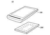
図1を参照して、本実施形態に係る通信システム10の概要について説明する。図1は、通信システム10の構成を示す図である。
<1. Overview of communication system>
An overview of a
通信システム10は、非接触式の無線通信で通信データの送受信を行う。通信システム10は、リーダ/ライタ機能を有する通信端末100と、ICチップが搭載されたICカード200とを有する。通信端末100は、本実施形態では携帯電話機等の携帯端末である。なお、通信システム10は、リーダ/ライタ機能を有する通信端末として、携帯端末の代わりに自動改札機を有しても良い。また、本実施形態では、ICカード200が外部装置に該当するが、ICチップを搭載した携帯電話機等の携帯端末が外部装置であっても良い。
The
通信システム10では、特定の周波数(例えば、13.56MHz)の搬送波が通信に使用されている。具体的には、通信端末100が搬送波信号をのせた搬送波を送信し、搬送波を後述する通信アンテナ204で受信したICカード200が、受信した搬送波信号に対する応答信号を返信することにより、通信端末100とICカード200が通信を行っている。
In the
次に、図2を参照して、通信端末100とICカード200の概略構成について説明する。図2は、通信端末100とICカード200の概略構成を示す回路図である。
Next, a schematic configuration of the
図2に示すように、通信端末100は、変調部102と、通信部の一例である通信アンテナ104とを有する。
As illustrated in FIG. 2, the
変調部102は、不図示の制御部からの搬送波信号の生成命令を受けて、命令に応じた搬送波信号を生成する。なお、搬送波信号には、例えばICカード200に対する各種処理命令や処理するデータを含めることができる。
The
通信アンテナ104は、例えば所定のインダクタンスを有するコイルを備え、変調部102が生成した搬送波信号をのせた搬送波を送信する。また、通信アンテナ104は、ICカード200からの応答信号を受信する。なお、図2では、通信アンテナ104が、コイルとキャパシタを含む共振回路で構成された例が示されている。
The
ICカード200は、図2に示すように、通信アンテナ204と、負荷Zとを有する。負荷Zは、ICカード200に搭載されるICチップを等価的に示したものである。
As shown in FIG. 2, the
通信アンテナ204は、例えば所定のインダクタンスを有するコイルを備え、通信アンテナ104から送信された搬送波信号がのった搬送波を受信する。また、通信アンテナ204は、負荷変調により、受信した搬送波に対する応答を行うことができる。
The
なお、通信端末100は、通信アンテナ104におけるアンテナ端Pの電圧を検出することにより、ICカード200からの応答信号を復調することができる。
ところで、通信システム10では、通信端末100とICカード200の相対位置(相対距離)が非接触通信に適した位置である場合には、正常に通信を行うことができる。しかし、通信端末100とICカード200は、携帯性を有しているため、通信端末100とICカード200の相対位置は変動しやすい。このため、通信端末100とICカード200の相対位置に応じて、非接触通信が失敗することがある。
By the way, in the
例えば、通信端末100とICカード200の距離が、非接触通信に適した適正距離から外れている場合や、通信端末100とICカード200がずれて位置している場合等には、非接触通信が失敗することがある。非接触通信の失敗時に、通信失敗状態を解消する必要があるが、通信端末100やICカード200の利用者は、通信失敗の原因や解消策を知らないケースがある。このため、利用者は、通信失敗状態を適切に解消できない。
For example, when the distance between the
そこで、上述した問題点を改善すべく、本実施形態に係る通信システム10は、通信状態が通信エラーと判定した場合には、通信エラー時の通信データに基いて通信端末100とICカード200との相対位置の変位を促す(例えば、通信端末100を移動させる)旨を報知させる処理(通信失敗時の報知処理)を行う。これにより、ユーザは、報知内容に基いて通信端末100とICカード200との相対位置を変えることで、通信エラー状態を解消することができる。なお、通信失敗時の報知処理の詳細については、後述する。
Therefore, in order to improve the above-described problem, the
<2.本実施形態に係る通信端末の詳細構成>
図3を参照して、本実施形態に係る通信端末100の詳細構成について説明する。図3は、通信端末100の詳細構成を示す図である。
<2. Detailed Configuration of Communication Terminal According to this Embodiment>
With reference to FIG. 3, a detailed configuration of the
図3に示すように、通信端末100は、アンテナコイル402と、共振用コンデンサ404と、非接触通信用IC406と、制御部の一例である携帯電話制御部408と、電圧測定部410と、表示部412と、振動部414と、発光部の一例であるLED416と、音声出力部の一例であるスピーカ418と、移動検出部の一例である加速度センサ420を備える。
As shown in FIG. 3, the
アンテナコイル402と共振用コンデンサ404は、図2の通信アンテナ104を構成する。また、アンテナコイル402と共振用コンデンサ404は、共振回路を形成している。
The
非接触通信用IC406は、通信端末100において非接触通信機能を実現させるためのものである。非接触通信用IC406は、非接触通信時に、ICカード200からの通信データのデータ受信が可能か否かを判定する。
The
ここで、図4を参照しながら、通信端末100がICカード200から受信する通信データについて説明する。図4は、通信データのデータ構造を示す図である。ICカード200から受信する通信データは、図4に示すようにパケットデータであり、プリアンブルと、SYNCコードと、データ本体部(単に、データとも呼ぶ)と、CRC(Cyclic Redundancy Check)を含む。
Here, communication data received from the
プリアンブルは、非接触通信の同期をとるためのものである。SYNCコードは、付加部分に該当し、データ本体部のスタート位置を示すコードである。データ本体部は、通信端末100で処理される実データである。CRCは、通信されるデータの誤りを検出するものである。なお、通信データは、プリアンブル、SYNCコード、データ本体部、CRCの順に受信される。すなわち、プリアンブルが最初に受信され、CRCが最後に受信される。
The preamble is for synchronizing non-contact communication. The SYNC code corresponds to the additional portion and is a code indicating the start position of the data body. The data body part is actual data processed by the
非接触通信用IC406は、通信失敗時の通信データにおける通信エラー箇所を判定する。具体的には、非接触通信用IC406は、図5に示すように、パケットデータの、プリアンブル、SYNCコード、データ本体部、CRCのいずれの部分で、通信エラーが発生したかを判定する。非接触通信用IC406は、プリアンブル、SYNCコード、データ本体部、CRCの順にエラー判定を行い、例えばプリアンブルでエラーと判定した場合には、SYNCコード、データ本体部、CRCについては判定を行わない。これにより、判定時間を短縮可能となる。非接触通信用IC406は、判定結果を携帯電話制御部408に出力する。
The
図5は、通信失敗例を示す図である。図5の失敗例1はパケットデータ中のプリアンブルで通信失敗が発生した場合を示し、失敗例2はSYNCコードで通信失敗が発生した場合を示し、失敗例3はデータ本体部で通信失敗が発生した場合を示し、失敗例4はCRCで通信失敗が発生した場合を示す。 FIG. 5 is a diagram illustrating an example of communication failure. Failure example 1 in FIG. 5 shows a case where a communication failure has occurred in the preamble in the packet data, failure example 2 shows a case where a communication failure has occurred in the SYNC code, and failure example 3 has caused a communication failure in the data body. Failure example 4 shows a case where a communication failure occurs in CRC.
電圧測定部410は、通信アンテナ104におけるアンテナ端Pの電圧を測定する。そして、電圧測定部410は、アンテナ端Pの電圧の測定結果を携帯電話制御部408に出力する。
The
本実施形態では、表示部412と、振動部414と、LED416と、スピーカ418の少なくともいずれか一つが、ユーザに通信端末100とICカード200との相対位置の変位(通信端末100の移動)を促す旨を報知する報知部として機能する。
In the present embodiment, at least one of the
表示部412は、各種の情報(メッセージ)を表示する。表示部412は、ICカード200との非接触通信の失敗時に、ユーザに通信端末100とICカード200との相対位置の変位を促すメッセージを表示する。例えば、表示部412は、図6に示すように、ユーザに通信端末100の移動を促すメッセージを表示する。
The
図6は、非接触通信の失敗時に、表示部412が通信端末100の移動を促すメッセージを表示する表示例を示す図である。図6の表示例1と表示例3には、通信端末100を上下左右のいずれかの方向に少しだけ移動させることを促すメッセージが示されている。表示例1と表示例3の違いは、表示例1の場合は通信端末100の移動量が小さいのに対して、表示例3の場合は通信端末100の移動量が大きい点にある。また、表示例2と表示例4には、ユーザに通信端末100を右方向に少しだけ移動させることを促すメッセージが示されている。表示例2と表示例4の違いは、表示例2の場合は通信端末100の移動量が小さいのに対して、表示例4の場合は通信端末100の移動量が大きい点にある。
FIG. 6 is a diagram illustrating a display example in which the
振動部414は、バイブレータを有し、通信端末100の本体を振動させる。振動部414は、非接触通信の失敗時に振動することで、通信エラー状態であると報知させることができる。また、振動部414は、非接触通信の失敗時に、振動の度合いを変えて振動しても良い。例えば、振動部414は、ユーザに通信端末100を大きく移動させることを促す場合には、大きく振動し、ユーザに通信端末100を小さく移動させることを促す場合には、小さく振動しても良い。また、振動部414は、振動のパターン(リズム)を変えて、通信端末100の移動方向を特定しても良い。
The
LED416は、複数の色の光を発する。LED416は、非接触通信の失敗時に、ユーザに通信端末100の移動を促すように光を発する。例えば、LED416は、通信端末100を左方向に移動させることを促す場合には赤色の光を発し、通信端末100を右方向に移動されることを促す場合には青色の光を発しても良い。また、LED416は、点灯パターンを変えて(例えば、点灯時間を変えて)、通信端末100の移動量の違いを報知しても良い。
The
スピーカ418は、音声を出力する。スピーカ418は、非接触通信の失敗時に、ユーザに通信端末100の移動を促すように音声(例えば、図6で表示部412が表示しているメッセージの音声)を出力する。
The
このように、表示部412等の報知部が、通信端末100とICカード200との相対位置の変位(通信端末100の移動)を促す旨を報知することで、ユーザは、非接触通信の失敗状態の解消策を知ることになる。このため、ユーザは、報知内容に基いて通信端末100とICカード200との相対位置を変える(通信端末100を移動させる)ことで、通信エラー状態を適切に解消することができる。
As described above, the notification unit such as the
加速度センサ420は、表示部412等の報知部による報知後に、通信端末100の移動等を検出する。例えば、加速度センサ420は、ユーザが通信端末100を移動した場合の、通信端末100の角度や移動を検出する。そして、加速度センサ420は、通信端末100の移動の検出結果を携帯電話制御部408に出力する。
The
携帯電話制御部408は、通信端末100である携帯電話の全体を制御する。携帯電話制御部408は、非接触通信用IC406による受信データの判定結果に基づいて、通信アンテナ104によるICカード200との通信状態を判定する。そして、携帯電話制御部408は、通信状態が通信エラーと判定した場合には、通信エラー時の通信データに基づいて通信端末100とICカード200との相対位置の変位(通信端末100の移動)を促す旨を表示部412等の報知部に報知させる。これにより、ユーザは、報知内容に基いて通信端末100とICカード200との相対位置を変える(通信端末100を移動させる)こととなる。
The mobile
携帯電話制御部408は、図4のパケットデータにおける通信エラー箇所に応じて、通信端末100とICカード200との相対位置の変位量(移動量)を変更して報知する。具体的には、携帯電話制御部408は、パケットデータにおけるICカード200からの受信順番が早い部分(例えば、プリアンブル)での通信エラーの場合の通信端末100の移動量を、受信順番が遅い部分(例えば、CRC)での通信エラーの場合の通信端末100の移動量よりも大きくする。
The mobile
ここで、パケットデータにおける通信エラー箇所に応じて、通信端末100の移動量を変更して報知する理由を説明する。前述したように、図4のパケットデータは、プリアンブル、SYNCコード、データ本体部、CRCの順に受信され、非接触通信用IC406は、プリアンブル、SYNCコード、データ本体部、CRCの順にエラー判定を行う。そして、SYNCで通信エラーの場合には、データ本体部及びCRCでも通信エラーの可能性が高く、通信端末100とICカード200の間の通信状態は悪いと想定できる。一方で、CRCで通信エラーの場合には、先に判定したプリアンブル、SYNCコード、データ本体部についてはエラーが無いので、プリアンブルでの通信エラーの場合に比べて通信エラーの度合いは小さいと想定できる。逆に言えば、プリアンブルやSYNCコードで通信エラーの場合には、通信状態が非常に悪いと言える。
Here, the reason why the amount of movement of the
そこで、本実施形態の通信端末100は、CRCでの通信エラーの場合には通信端末100を小さい移動させる旨を報知し、プリアンブルやSYNCでの通信エラーの場合には通信端末100を大きく移動させる旨を報知する。よって、パケットデータにおける通信エラー箇所に応じて、通信端末100の移動量を変更して報知することで、ユーザはより適切に通信エラー状態を解消することができる。
Therefore, the
携帯電話制御部408は、加速度センサ420による通信端末100の移動検出後も通信エラーが継続していると判定した場合には、加速度センサ420により検出された移動方向とは異なる方向(例えば、逆方向)への移動を、表示部412等の報知部に報知させる。これにより、直前の報知後の通信端末100の移動で通信エラーを解消できなくても、ユーザが通信端末100を直前の移動方向とは異なる方向へ移動させることで、通信エラーを解消することができる。特に、逆方向への移動を促す旨を報知することで、仮に直前の移動が通信エラー状態を悪化させる移動であった場合に、効果的に通信エラー状態を解消できる。
If the mobile
携帯電話制御部408は、パケットデータのプリアンブル又はSYNCコードで通信エラーが発生していると判定された場合には、電圧測定部410にアンテナ端Pの電圧を測定させる。一方で、携帯電話制御部408は、パケットデータのデータ本体部やCRCで通信エラーが発生していると判定された場合には、電圧測定部410にアンテナ端Pの電圧を測定させない。これは、プリアンブル又はSYNCコードで通信エラーが発生している場合には、通信エラーの度合いが大きいため、通信エラーを解消するためにアンテナ端Pの測定電圧を利用するためである。
When it is determined that a communication error has occurred in the preamble of the packet data or the SYNC code, the mobile
携帯電話制御部408は、通信状態が通信エラーと判定した場合には、電圧測定部410によるアンテナ端Pの電圧の測定後に、通信端末100とICカード200との相対位置の変位を促す旨を表示部412等の報知部に報知させる。そして、携帯電話制御部408は、報知部による報知後に再度測定されたアンテナ端Pの電圧が、報知前に測定された電圧よりも小さい場合には、報知部に報知態様を変えて報知させる。例えば、携帯電話制御部408は、直前の報知での通信端末100の移動方向とは異なる方向への移動を報知させる。これにより、通信アンテナ104がICカード200との通信に適した位置に位置するように、通信端末100の移動を誘導させることができるため、通信エラー状態を解消しやすくなる。
When the mobile
通信端末100は、CPU(前述した携帯電話制御部408を構成する)、ROM、RAM等を有する。CPUは、ROMや外部の記憶装置等から読み出されたプログラムをRAM上に展開して実行することで、各種の処理(後述する通信失敗時の報知処理等)を実現する。なお、プログラムは、記録媒体に記録されたり、インターネットを介してダウンロードされうる。
The
<3.通信失敗時の報知処理>
図7A及び図7Bを参照して、通信失敗時の報知処理について説明する。図7A及び図7Bは、通信失敗時の報知処理を説明するためのフローチャートである。本処理は、CPUがROM等に記憶されたプログラムを実行することで、実現される。
<3. Notification process when communication fails>
With reference to FIG. 7A and FIG. 7B, the notification process at the time of communication failure is demonstrated. 7A and 7B are flowcharts for explaining notification processing when communication fails. This process is realized by the CPU executing a program stored in the ROM or the like.
図7Aのフローチャートは、通信端末100の電源がONされた状態から開始される。まず、通信端末100の非接触通信用IC406は、ICカード200からの搬送波の有無の判定を行う(ステップS102)。
The flowchart of FIG. 7A starts from a state where the
ステップS102でICカード200からの搬送波が無いと判定された場合には、非接触通信用IC406は、ICカード200からの搬送波を待ち続ける。
If it is determined in step S102 that there is no carrier wave from the
一方で、ステップS102でICカード200からの搬送波が有りと判定された場合には、非接触通信用IC406は、ICカード200からのデータ受信が可能か否かを判定する(ステップS104)。すなわち、非接触通信用IC406は、データを含む搬送波信号を受信できるか否かを判定する。
On the other hand, if it is determined in step S102 that there is a carrier wave from the
ステップS104でデータ受信が可能と判定された場合には、非接触通信用IC406は、通常の信号処理を行う(ステップS106)。例えば、非接触通信用IC406は、受信したデータの信号処理を行う。これにより、本処理は終了する。
If it is determined in step S104 that data can be received, the
ステップS104でデータ受信が不可能と判定された場合には、非接触通信用IC406は、エラー判定を行う(ステップS108)。具体的には、非接触通信用IC406は、ICカード200からのパケットデータ(図4)中のどの部分でエラーが発生しているかを判定する。この際、非接触通信用IC406は、パケットデータのプリアンブル、SNYCコード、データ本体部、CRCの順(すなわち、通信データの受信順)に、エラー判定を行う。
If it is determined in step S104 that data cannot be received, the
(CRC部分がエラーの場合)
ステップS108でCRCがエラー(図5の失敗例4)と判定された場合には、携帯電話制御部408は、例えば図6の表示例1のように、表示部412に「少しだけ上下左右に動かしてください」というメッセージを表示させる(ステップS110)。表示部412に表示されたメッセージを見たユーザは、通信不良状態を解消すべく、通信端末100を上下左右のいずれかの方向に移動させることになる。なお、ユーザが通信端末100をいずれの方向に移動させたかは、加速度センサ420によって検出される。
(When CRC part is error)
If it is determined in step S108 that the CRC is an error (failure example 4 in FIG. 5), the mobile
次に、非接触通信用IC406は、再度、ICカード200からのデータ受信が可能か否かを判定する(ステップS112)。具体的には、非接触通信用IC406は、ステップ110の表示後に通信端末100の移動を検出した場合に、データ受信が可能か否かを判定する。
Next, the
ステップS112で、通信端末100の移動によって通信状態が改善されてデータ受信が可能と判定された場合には、非接触通信用IC406は、前述したステップS106の信号処理を行う。
If it is determined in step S112 that the communication state is improved due to movement of the
ステップS112で、通信端末100を移動してもデータ受信が不可能と判定された場合には、携帯電話制御部408は、直前に移動した方向とは逆方向に「少しだけ動かしてください」というメッセージを表示部412に表示させる(ステップS114)。例えば、ステップS110の表示後に、加速度センサ420によって通信端末100の左方向の移動が検出された場合には、携帯電話制御部408は、図6の表示例2のように、表示部412に「少しだけ右方向に移動してください」というメッセージを表示させる。表示部412に表示されたメッセージを見たユーザは、通信不良状態を解消すべく、通信端末100を右方向に移動させることになる。
If it is determined in step S112 that data cannot be received even if the
次に、非接触通信用IC406は、ステップS112と同様に、ICカード200からのデータ受信が可能か否かを判定する(ステップS116)。そして、ステップS116でデータ受信が可能と判定された場合には、非接触通信用IC406はステップS106の信号処理を行う。
Next, the
ステップS116でデータ受信が不可能と判定された場合には、携帯電話制御部408は、表示部412に通信失敗の表示(例えば図9の表示)を行う(ステップS118)。これにより、本処理が終了し、ユーザはリトライすることになる。なお、ステップS116でデータ受信が不可能と判定された場合には、通信失敗の表示に代えて、再度ステップS108のエラー判定を繰り返しても良い。
If it is determined in step S116 that data cannot be received, the cellular
(データ本体部がエラーの場合)
ステップS108でデータ本体部がエラー(図5の失敗例3)と判定された場合には、携帯電話制御部408は、例えば図6の表示例3のように、表示部412に「上下左右に動かしてください」というメッセージを表示させる(ステップS120)。ステップS120で表示されるメッセージ内容は、ステップS110で表示されるメッセージ内容と異なり、通信端末100を大きく移動させることを促している。
(When data body part is error)
If it is determined in step S108 that the data body portion is an error (failure example 3 in FIG. 5), the mobile
次に、非接触通信用IC406は、再度、ICカード200からのデータ受信が可能か否かを判定する(ステップS122)。ステップS122で、通信端末100の移動によってデータ受信が可能と判定された場合には、非接触通信用IC406は、前述したステップS106の信号処理を行う。
Next, the
ステップS122で、通信端末100が移動してもデータ受信が不可能と判定された場合には、携帯電話制御部408は、直前に移動した方向とは逆方向に「動かしてください」というメッセージを表示部412に表示させる(ステップS124)。例えば、ステップS120の表示後に、加速度センサ420によって通信端末100の左方向の移動が検出された場合には、携帯電話制御部408は、図6の表示例4のように、表示部412に「右方向に移動してください」というメッセージを表示させる。
If it is determined in step S122 that data cannot be received even if the
次に、非接触通信用IC406は、ステップS122と同様に、ICカード200からのデータ受信が可能か否かを判定する(ステップS126)。そして、ステップS126でデータ受信が可能と判定された場合には、非接触通信用IC406はステップS106の信号処理を行う。
Next, the
ステップS126でデータ受信が不可能と判定された場合には、非接触通信用IC406は、再度、ステップ108のエラー判定を行う。再度エラー判定を行う理由は、データ受信が出来ない原因が、パケットデータ中のデータ本体部以外の部分(例えば、CRC)でエラーが発生している可能性があり、このエラーを解消するためである。
If it is determined in step S126 that data cannot be received, the
(SNYCコード又はプリアンブルがエラーの場合)
ステップS108でパケットデータ中のSNYCコード又はプリアンブルがエラー(図5の失敗例1、失敗例2)と判定された場合には、電圧測定部410は、通信アンテナ104のアンテナ端Pの電圧を確認する(ステップS128)。
(When SNYC code or preamble is an error)
If it is determined in step S108 that the SNYC code or preamble in the packet data is an error (failure example 1, failure example 2 in FIG. 5), the
次に、携帯電話制御部408は、前述したステップS120と同様に、表示部412に「上下左右に動かしてください」というメッセージを表示させる(ステップS130)。これにより、ユーザは通信端末100を移動させることになる。通信端末100が移動すると、電圧測定部410は、通信端末100の移動に伴いアンテナ端Pの電圧が上がったか下がったかを判定する(ステップS132)。
Next, the cellular
ステップS132でアンテナ端Pの電圧が下がったと判定された場合には、携帯電話制御部408は、直前に移動した方向とは逆方向に「動かしてください」というメッセージを表示部412に表示させる(ステップS134)。例えば、ステップS130の表示後に、加速度センサ420によって通信端末100の左方向の移動が検出された場合には、携帯電話制御部408は、表示部412に「右方向に移動してください」というメッセージを表示させる。
If it is determined in step S132 that the voltage at the antenna terminal P has dropped, the mobile
次に、非接触通信用IC406は、再度、ICカード200からのデータ受信が可能か否かを判定する(ステップS136)。ステップS136で通信端末100の移動によってデータ受信が可能と判定された場合には、非接触通信用IC406は、前述したステップS106の信号処理を行う。
Next, the
ステップS136で通信端末100が移動してもデータ受信が不可能と判定された場合には、非接触通信用IC406は、再度、ステップ108のエラー判定を行う。エラー判定を再度行う理由は、パケットデータ中のSNYC部分とプリアンブル部分以外の部分(例えば、CRC部分)でエラーが発生している可能性があり、このエラーを解消するためである。
If it is determined in step S136 that data cannot be received even if the
ステップS132でアンテナ端Pの電圧が上がったと判定された場合には、非接触通信用IC406は、再度、ICカード200からのデータ受信が可能か否かを判定する(ステップS138)。ステップS138でデータ受信が可能と判定された場合には、非接触通信用IC406は、前述したステップS106の信号処理を行う。
If it is determined in step S132 that the voltage at the antenna end P has increased, the
ステップS136でデータ受信が不可能と判定された場合には、非接触通信用IC406は、ステップS136と同様に、再度ステップ108のエラー判定を行う。
If it is determined in step S136 that data cannot be received, the
上述した本処理によれば、非接触通信の失敗時に通信端末100を移動させるようなメッセージ(図6)を表示部412に表示させることで、ユーザに通信端末100の移動を促すことができる。このため、ユーザが通信端末100を適切な位置に移動させることで、通信失敗時の適切なリカバリーが可能となる。
According to the processing described above, a message (FIG. 6) that moves the
なお、本処理においては、通信失敗時に通信端末100の移動を促すために、表示部412にメッセージを表示させることとしたが、これに限定されない。例えば、スピーカ418からの音声出力、LED416の点灯、振動部414の振動等で、通信端末100の移動を促すことを報知しても良い。
In this process, a message is displayed on the
また、表示部412、スピーカ418、LED416、振動部414のうちの複数を組み合わせて(例えば、表示部412による表示と、LED416の点灯)、報知しても良い。
In addition, a combination of a plurality of the
<4.まとめ>
上述したように、本実施形態に係る通信端末100は、通信アンテナ104によるICカードとの通信状態を判定し、通信状態が通信エラーと判定した場合には、通信エラー時の通信データに基づいて通信端末100とICカード200との相対位置の変位を促す旨を表示部412等の報知部に報知させる。報知部の報知内容により、ユーザは、非接触通信の失敗の解消策を知ることになる。このため、ユーザは、報知内容に基いて通信端末100とICカード200との相対位置を変える(通信端末100を移動させる)ことで、通信エラー状態を適切に解消することができる。
<4. Summary>
As described above, the
ここで、図8と図9に示す比較例と対比して、本実施形態に係る通信端末100の有効性について、更に説明する。図8は、比較例に係る通信端末の構成を示す図である。図9は、比較例に係る通信端末の表示部の表示例を示す図である。
Here, the effectiveness of the
まず、比較例について説明する。比較例に係る通信端末700の表示部712は、非接触通信の失敗時には、図9に示すメッセージ(通信エラーメッセージ)を表示する。このため、図9のメッセージを見たユーザは、通信エラー状態であることは分かるが、通信エラーの原因や改善方法は分からない。このため、通信エラーが発生し際に、ユーザは適切に通信エラー状態を解消することが困難とある。
First, a comparative example will be described. The
これに対して、本実施形態では、例えば図6に示すように、通信エラーを解消するために通信端末100の移動を促すメッセージを表示する。このため、図9に示す表示とは異なり、ユーザは具体的な対処方法を知ることができるので、通信エラー状態を解消しやすくなる。
On the other hand, in this embodiment, for example, as shown in FIG. 6, a message that prompts the user to move the
また、本実施形態の通信端末100は、図8に示す通信端末700の構成とは異なり、電圧測定部410の測定結果を確認して報知部に報知するので、通信アンテナ104が適切な位置に位置するように通信端末100を移動させることができる。
Further, unlike the configuration of the
以上、添付図面を参照しながら本開示の好適な実施形態について詳細に説明したが、本技術はかかる例に限定されない。本開示の技術分野における通常の知識を有する者であれば、特許請求の範囲に記載された技術的思想の範疇内において、各種の変更例または修正例に想到し得ることは明らかであり、これらについても、当然に本開示の技術的範囲に属するものと了解される。 The preferred embodiments of the present disclosure have been described in detail above with reference to the accompanying drawings, but the present technology is not limited to such examples. It is obvious that a person having ordinary knowledge in the technical field of the present disclosure can come up with various changes or modifications within the scope of the technical idea described in the claims. Of course, it is understood that it belongs to the technical scope of the present disclosure.
また、上記実施形態では、通信端末として携帯電話機や自動改札機を例に挙げて説明したが、これに限定されない。通信端末は、リーダ/ライタ機能及び報知部を有する、デジタルカメラ、PDA、ゲーム機、電子辞書、タブレット等であっても良い。 In the above embodiment, a mobile phone or an automatic ticket gate has been described as an example of the communication terminal. However, the present invention is not limited to this. The communication terminal may be a digital camera, PDA, game machine, electronic dictionary, tablet or the like having a reader / writer function and a notification unit.
また、上記の実施形態のフローチャートに示されたステップは、記載された順序に沿って時系列的に行われる処理はもちろん、必ずしも時系列的に処理されなくとも、並列的に又は個別的に実行される処理をも含む。また時系列的に処理されるステップでも、場合によっては適宜順序を変更することが可能であることは言うまでもない。 In addition, the steps shown in the flowcharts of the above-described embodiments are executed in parallel or individually even if they are not necessarily processed in time series, as well as processes performed in time series in the order described. Including processing to be performed. Further, it goes without saying that the order can be appropriately changed even in the steps processed in time series.
なお、本技術は以下のような構成も取ることができる。
(1)外部装置と非接触通信を行う通信部と、
報知部と、
前記通信部による前記外部装置との通信状態を判定し、通信状態が通信エラーと判定した場合には、通信エラー時の通信データに基づいて自端末と前記外部装置との相対位置の変位を促す旨を前記報知部に報知させる制御部と、
を備える、通信端末。
(2)前記通信データは、前記外部装置から受信したパケットデータであり、
前記制御部は、前記パケットデータにおける通信エラー箇所に応じて、前記相対位置の変位量を変更する、前記(1)に記載の通信端末。
(3)前記制御部は、前記パケットデータにおける前記外部装置からの受信順番が早い部分での通信エラーの場合の前記相対位置の変位量を、前記受信順番が遅い部分での通信エラーの場合の前記相対位置の変位量よりも大きくして、前記報知部に報知させる、前記(2)に記載の通信端末。
(4)前記パケットデータは、前記受信順番が遅いデータ本体部分と、前記受信順番が早く前記データ本体部分の開始位置を示す付加部分とを含み、
前記通信部における電圧を測定する電圧測定部を更に備え、
前記制御部は、前記データ本体部分と前記付加部分のうちの前記付加部分で通信エラーが発生していると判定した場合に、前記電圧測定部に前記電圧を測定させる、前記(3)に記載の通信端末。
(5)前記制御部は、
通信状態が通信エラーと判定した場合には、前記電圧測定部による前記電圧の測定後に、前記相対位置の変位を促す旨を前記報知部に報知させ、
前記報知部による報知後に再度測定された前記電圧が、報知前に測定された前記電圧よりも小さい場合には、前記報知部に報知態様を変えて報知させる、前記(4)に記載の通信端末。
(6)前記制御部は、前記相対位置の変位として、前記自端末の所定方向への移動を前記報知部に報知させる、前記(1)から(5)のいずれかに記載の通信端末。
(7)前記報知部による報知後に前記自端末の移動を検出する移動検出部を更に備え、
前記制御部は、前記移動検出部による移動検出後も前記通信エラーが継続していると判定した場合には、前記移動検出部により検出された移動方向とは異なる方向への移動を前記報知部に報知させる、前記(6)に記載の通信端末。
(8)前記制御部は、前記移動検出部による移動検出後も前記通信エラーが継続していると判定した場合には、前記移動検出部により検出された移動方向とは逆方向への移動を前記報知部に報知させる、前記(7)に記載の通信端末。
(9)前記報知部は、情報を表示する表示部と、光を発する発光部と、前記端末本体を振動させる振動部と、音声を出力する音声出力部との少なくともいずれか一つである、前記(1)から(8)のいずれかに記載の通信端末。
(10)通信端末が外部装置と非接触通信を行うことと、
前記通信端末が前記外部装置との通信状態を判定することと、
通信エラーと判定した場合に、通信エラー時の通信データに基づいて前記通信端末と前記外部装置との相対位置の変位を促す旨を前記通信端末の報知部に報知させることと、
を有する、通信方法。
(11)通信端末が外部装置と非接触通信を行うことと、
前記通信端末が前記外部装置との通信状態を判定することと、
通信エラーと判定した場合に、通信エラー時の通信データに基づいて前記通信端末と前記外部装置との相対位置の変位を促す旨を前記通信端末の報知部に報知させることと、
をコンピュータに実行させるための、プログラム。
In addition, this technique can also take the following structures.
(1) a communication unit that performs non-contact communication with an external device;
A notification unit;
When the communication unit determines a communication state with the external device, and the communication state is determined to be a communication error, it prompts the displacement of the relative position between the own terminal and the external device based on communication data at the time of the communication error. A control unit for informing the notification unit of the effect,
A communication terminal.
(2) The communication data is packet data received from the external device,
The said control part is a communication terminal as described in said (1) which changes the displacement amount of the said relative position according to the communication error location in the said packet data.
(3) The control unit determines the amount of displacement of the relative position in the case of a communication error in the part in which the reception order from the external device is early in the packet data in the case of a communication error in the part in which the reception order is late. The communication terminal according to (2), which is larger than a displacement amount of the relative position and is caused to be notified to the notification unit.
(4) The packet data includes a data body portion with the late reception order and an additional portion indicating the start position of the data body portion with the early reception order,
A voltage measuring unit for measuring a voltage in the communication unit;
The said control part makes the said voltage measurement part measure the said voltage, when it determines with the communication error having generate | occur | produced in the said additional part of the said data main-body part and the said additional part, Said (3). Communication terminal.
(5) The control unit
If the communication state is determined to be a communication error, after the measurement of the voltage by the voltage measurement unit, to inform the notification unit that the displacement of the relative position is urged,
The communication terminal according to (4), wherein when the voltage measured again after the notification by the notification unit is smaller than the voltage measured before the notification, the notification unit changes the notification mode to notify. .
(6) The communication terminal according to any one of (1) to (5), wherein the control unit causes the notification unit to notify the movement of the terminal in a predetermined direction as the displacement of the relative position.
(7) It further includes a movement detection unit that detects movement of the terminal after notification by the notification unit,
When the control unit determines that the communication error continues after the movement is detected by the movement detection unit, the control unit reports a movement in a direction different from the movement direction detected by the movement detection unit. The communication terminal according to (6), wherein the communication terminal is notified.
(8) When the control unit determines that the communication error continues after the movement is detected by the movement detection unit, the control unit moves in the direction opposite to the movement direction detected by the movement detection unit. The communication terminal according to (7), wherein the notification unit is notified.
(9) The notification unit is at least one of a display unit that displays information, a light emitting unit that emits light, a vibration unit that vibrates the terminal body, and an audio output unit that outputs audio. The communication terminal according to any one of (1) to (8).
(10) the communication terminal performs contactless communication with an external device;
The communication terminal determining a communication state with the external device;
If it is determined as a communication error, informing the notification unit of the communication terminal that the displacement of the relative position between the communication terminal and the external device is urged based on communication data at the time of the communication error;
A communication method.
(11) the communication terminal performs contactless communication with an external device;
The communication terminal determining a communication state with the external device;
If it is determined as a communication error, informing the notification unit of the communication terminal that the displacement of the relative position between the communication terminal and the external device is urged based on communication data at the time of the communication error;
A program that causes a computer to execute.
10 通信システム
100 通信端末
102 変調部
104 通信アンテナ
200 ICカード
204 通信アンテナ
402 アンテナコイル
404 共振用コンデンサ
406 非接触通信用IC
408 携帯電話制御部
410 電圧測定部
412 表示部
414 振動部
416 LED
418 スピーカ
420 加速度センサ
DESCRIPTION OF
408 Mobile
Claims (9)
報知部と、
前記通信部による前記外部装置との通信状態を判定し、通信状態が通信エラーと判定した場合には、通信エラー時の通信データに基づいて自端末と前記外部装置との相対位置の変位を促す旨を前記報知部に報知させる制御部と、
を備え、
前記制御部は、前記相対位置の変位として、前記自端末の所定方向への移動を前記報知部に報知させ、
前記通信データは、前記外部装置から受信したパケットデータであり、
前記制御部は、前記パケットデータにおける通信エラー箇所に応じて、前記相対位置の変位内容を変更する、通信端末。 A communication unit that performs non-contact communication with an external device;
A notification unit;
When the communication unit determines a communication state with the external device, and the communication state is determined to be a communication error, it prompts the displacement of the relative position between the own terminal and the external device based on communication data at the time of the communication error. A control unit for informing the notification unit of the effect,
With
The control unit causes the notification unit to notify the movement of the terminal in a predetermined direction as the displacement of the relative position ,
The communication data is packet data received from the external device,
Wherein, in accordance with the communication error location in the packet data, to change the displacement contents of the relative position, the communication terminal.
前記通信部における電圧を測定する電圧測定部を更に備え、 A voltage measuring unit for measuring a voltage in the communication unit;
前記制御部は、前記データ本体部分と前記付加部分のうちの前記付加部分で通信エラーが発生していると判定した場合に、前記電圧測定部に前記電圧を測定させる、請求項2に記載の通信端末。 The control unit according to claim 2, wherein the control unit causes the voltage measurement unit to measure the voltage when it is determined that a communication error has occurred in the additional part of the data body part and the additional part. Communication terminal.
通信状態が通信エラーと判定した場合には、前記電圧測定部による前記電圧の測定後に、前記相対位置の変位を促す旨を前記報知部に報知させ、 If the communication state is determined to be a communication error, after the measurement of the voltage by the voltage measurement unit, to inform the notification unit that the displacement of the relative position is urged,
前記報知部による報知後に再度測定された前記電圧が、報知前に測定された前記電圧よりも小さい場合には、前記報知部に報知態様を変えて報知させる、請求項3に記載の通信端末。 The communication terminal according to claim 3, wherein when the voltage measured again after the notification by the notification unit is smaller than the voltage measured before the notification, the notification unit changes the notification mode to notify.
前記制御部は、前記移動検出部による移動検出後も前記通信エラーが継続していると判定した場合には、前記移動検出部により検出された移動方向とは異なる方向への移動を前記報知部に報知させる、請求項1に記載の通信端末。 When the control unit determines that the communication error continues after the movement is detected by the movement detection unit, the control unit reports a movement in a direction different from the movement direction detected by the movement detection unit. The communication terminal according to claim 1, wherein the communication terminal is notified.
前記通信端末が前記外部装置との通信状態を判定することと、 The communication terminal determining a communication state with the external device;
通信エラーと判定した場合に、通信エラー時の通信データである前記外部装置から受信したパケットデータに基づいて、前記通信端末と前記外部装置との相対位置の変位を促す旨を前記通信端末の報知部に報知させることと、 When the communication terminal determines that a communication error has occurred, based on the packet data received from the external device that is communication data at the time of the communication error, the communication terminal informs the user that the displacement of the relative position between the communication terminal and the external device is urged. Letting the department know,
前記相対位置の変位として、前記通信端末の所定方向への移動を前記報知部に報知させることと、 Causing the notification unit to notify the movement of the communication terminal in a predetermined direction as the displacement of the relative position;
前記パケットデータにおける通信エラー箇所に応じて、前記相対位置の変位内容を変更することと、 According to a communication error location in the packet data, changing the displacement content of the relative position,
を有する、通信方法。 A communication method.
前記通信端末が前記外部装置との通信状態を判定することと、 The communication terminal determining a communication state with the external device;
通信エラーと判定した場合に、通信エラー時の通信データである前記外部装置から受信したパケットデータに基づいて、前記通信端末と前記外部装置との相対位置の変位を促す旨を前記通信端末の報知部に報知させることと、 When the communication terminal determines that a communication error has occurred, based on the packet data received from the external device that is communication data at the time of the communication error, the communication terminal informs the user that the displacement of the relative position between the communication terminal and the external device is urged. Letting the department know,
前記相対位置の変位として、前記通信端末の所定方向への移動を前記報知部に報知させることと、 Causing the notification unit to notify the movement of the communication terminal in a predetermined direction as the displacement of the relative position;
前記パケットデータにおける通信エラー箇所に応じて前記相対位置の変位内容を変更することと、 Changing the displacement content of the relative position according to the communication error location in the packet data;
をコンピュータに実行させるための、プログラム。 A program that causes a computer to execute.
Priority Applications (5)
| Application Number | Priority Date | Filing Date | Title |
|---|---|---|---|
| JP2011074425A JP5670798B2 (en) | 2011-03-30 | 2011-03-30 | Communication terminal, communication method, and program |
| EP12156554.3A EP2506543B1 (en) | 2011-03-30 | 2012-02-22 | Communication terminal, communication method, and program |
| TW101109665A TWI530139B (en) | 2011-03-30 | 2012-03-21 | Communication terminal, communication method, and program |
| CN201210080531.7A CN102739853B (en) | 2011-03-30 | 2012-03-23 | Communication terminal, communication means and program |
| US13/428,394 US9083813B2 (en) | 2011-03-30 | 2012-03-23 | Communication terminal, communication method, and program |
Applications Claiming Priority (1)
| Application Number | Priority Date | Filing Date | Title |
|---|---|---|---|
| JP2011074425A JP5670798B2 (en) | 2011-03-30 | 2011-03-30 | Communication terminal, communication method, and program |
Publications (3)
| Publication Number | Publication Date |
|---|---|
| JP2012208771A JP2012208771A (en) | 2012-10-25 |
| JP2012208771A5 JP2012208771A5 (en) | 2014-05-08 |
| JP5670798B2 true JP5670798B2 (en) | 2015-02-18 |
Family
ID=45656451
Family Applications (1)
| Application Number | Title | Priority Date | Filing Date |
|---|---|---|---|
| JP2011074425A Active JP5670798B2 (en) | 2011-03-30 | 2011-03-30 | Communication terminal, communication method, and program |
Country Status (5)
| Country | Link |
|---|---|
| US (1) | US9083813B2 (en) |
| EP (1) | EP2506543B1 (en) |
| JP (1) | JP5670798B2 (en) |
| CN (1) | CN102739853B (en) |
| TW (1) | TWI530139B (en) |
Families Citing this family (5)
| Publication number | Priority date | Publication date | Assignee | Title |
|---|---|---|---|---|
| JP6012204B2 (en) * | 2012-03-06 | 2016-10-25 | 株式会社メガチップス | POSITIONING SYSTEM, TERMINAL DEVICE, PROGRAM, AND POSITIONING METHOD |
| US9400904B2 (en) * | 2014-06-13 | 2016-07-26 | Verily Life Sciences Llc | System for aligning a handheld RFID reader |
| JP6381056B2 (en) * | 2015-01-08 | 2018-08-29 | Necディスプレイソリューションズ株式会社 | Portable terminal, data communication system, data communication method, program |
| US10009491B2 (en) * | 2015-04-06 | 2018-06-26 | Kyocera Document Solutions Inc. | Image formation apparatus |
| SG11202102799RA (en) | 2018-10-02 | 2021-04-29 | Capital One Services Llc | Systems and methods for cryptographic authentication of contactless cards |
Family Cites Families (37)
| Publication number | Priority date | Publication date | Assignee | Title |
|---|---|---|---|---|
| US5029183A (en) * | 1989-06-29 | 1991-07-02 | Symbol Technologies, Inc. | Packet data communication network |
| JP3240017B2 (en) * | 1993-01-11 | 2001-12-17 | ソニー株式会社 | MPEG signal recording method and MPEG signal reproducing method |
| SG54559A1 (en) * | 1996-09-13 | 1998-11-16 | Hitachi Ltd | Power transmission system ic card and information communication system using ic card |
| US5945660A (en) * | 1996-10-16 | 1999-08-31 | Matsushita Electric Industrial Co., Ltd. | Communication system for wireless bar code reader |
| JP3111966B2 (en) * | 1998-01-30 | 2000-11-27 | 日本電気株式会社 | Mobile phone equipment |
| JP2000251038A (en) * | 1999-03-03 | 2000-09-14 | Toshiba Corp | Radio information storage medium and method for arranging radio information storage medium |
| US6307468B1 (en) * | 1999-07-20 | 2001-10-23 | Avid Identification Systems, Inc. | Impedance matching network and multidimensional electromagnetic field coil for a transponder interrogator |
| JP4868195B2 (en) * | 2000-10-24 | 2012-02-01 | ソニー株式会社 | Electronic apparatus and information processing apparatus |
| JP2005045557A (en) * | 2003-07-22 | 2005-02-17 | Sony Corp | Communication device |
| JP2005071102A (en) * | 2003-08-25 | 2005-03-17 | Toshiba Corp | Wireless communication machine and wireless communication method |
| EP1744475B1 (en) * | 2004-05-31 | 2017-07-26 | Casio Computer Co., Ltd. | Information reception device, information transmission system, and information reception method |
| US7229021B2 (en) * | 2004-06-07 | 2007-06-12 | Nokia Corporation | Indicia reader with synchronized light source and associated methods and computer program product |
| US7667572B2 (en) * | 2004-07-30 | 2010-02-23 | Reva Systems Corporation | RFID tag data acquisition system |
| US7319396B2 (en) * | 2004-08-16 | 2008-01-15 | Abr, Llc | RFID transducer alignment system |
| US7375616B2 (en) * | 2004-09-08 | 2008-05-20 | Nokia Corporation | Electronic near field communication enabled multifunctional device and method of its operation |
| JP5100966B2 (en) * | 2005-01-17 | 2012-12-19 | ソニーモバイルコミュニケーションズ株式会社 | Non-contact short-range wireless communication device, mobile phone terminal |
| JP2007005999A (en) * | 2005-06-22 | 2007-01-11 | Denso Wave Inc | Communication apparatus and notification control method of communication apparatus |
| US20070141997A1 (en) * | 2005-12-15 | 2007-06-21 | Symbol Technologies, Inc. | Radio frequency identification (RFID) antenna integration techniques in mobile devices |
| US8873457B2 (en) * | 2006-03-15 | 2014-10-28 | Freescale Semiconductor, Inc. | Method and apparatus for enhanced data rate adaptation and lower power control in a WLAN semiconductor chip |
| US7769345B2 (en) * | 2006-09-29 | 2010-08-03 | Sony Ericsson Mobile Communications Ab | Device and method for guiding a user to a communication position |
| US7840237B2 (en) * | 2007-02-08 | 2010-11-23 | Microsoft Corporation | Enabling user interface elements based on short range wireless devices |
| JP5033532B2 (en) * | 2007-07-30 | 2012-09-26 | 京セラ株式会社 | Communication terminal |
| JP2009140406A (en) * | 2007-12-10 | 2009-06-25 | Sanden Corp | Noncontact ic chip reader/writer |
| JP4572936B2 (en) * | 2008-01-18 | 2010-11-04 | ソニー株式会社 | Remote control device and communication system |
| KR101527185B1 (en) * | 2008-02-29 | 2015-06-08 | 삼성전자 주식회사 | RFID system and method for transmitting large data of passive RFID |
| US8014791B2 (en) * | 2008-06-30 | 2011-09-06 | Intelligent Sciences, Ltd. | Method and system for determining position of a wireless electronic device within a volume |
| KR101524616B1 (en) * | 2008-07-07 | 2015-06-02 | 엘지전자 주식회사 | Controlling a Mobile Terminal with a Gyro-Sensor |
| US8126433B2 (en) * | 2008-09-15 | 2012-02-28 | Sony Ericsson Mobile Communications Ab | Electronic devices and methods that communicate via transferjet and NFC transmitter and receiver pairing |
| US8138938B2 (en) * | 2008-10-28 | 2012-03-20 | The Boeing Company | Hand-held positioning interface for spatial query |
| JP2010118773A (en) * | 2008-11-11 | 2010-05-27 | Toshiba Corp | Wireless communication terminal |
| US8384679B2 (en) * | 2008-12-23 | 2013-02-26 | Todd Robert Paleczny | Piezoelectric actuator arrangement |
| FR2942060B1 (en) * | 2009-02-11 | 2016-02-12 | Oberthur Technologies | ELECTRONIC ENTITY CAPABLE OF COMMUNICATING WITH A READER AND METHOD IMPLEMENTED WITHIN SUCH AN ELECTRONIC ENTITY |
| JP5223736B2 (en) | 2009-03-11 | 2013-06-26 | パナソニック株式会社 | Information reader |
| US8593255B2 (en) * | 2009-04-24 | 2013-11-26 | Nokia Corporation | Method and apparatus for providing user interaction via transponders |
| JP2011003948A (en) * | 2009-06-16 | 2011-01-06 | Sony Corp | Data processing apparatus and method, receiving apparatus and method, synchronous detection apparatus and method, and computer program |
| US9455768B2 (en) * | 2009-09-24 | 2016-09-27 | Blackberry Limited | Communications device, method and system for establishing wireless communications between communications devices |
| JP2011074425A (en) | 2009-09-29 | 2011-04-14 | Sumitomo Electric Ind Ltd | Method for producing composite material, and composite material |
-
2011
- 2011-03-30 JP JP2011074425A patent/JP5670798B2/en active Active
-
2012
- 2012-02-22 EP EP12156554.3A patent/EP2506543B1/en active Active
- 2012-03-21 TW TW101109665A patent/TWI530139B/en active
- 2012-03-23 CN CN201210080531.7A patent/CN102739853B/en active Active
- 2012-03-23 US US13/428,394 patent/US9083813B2/en active Active
Also Published As
| Publication number | Publication date |
|---|---|
| TWI530139B (en) | 2016-04-11 |
| US20120249337A1 (en) | 2012-10-04 |
| CN102739853A (en) | 2012-10-17 |
| US9083813B2 (en) | 2015-07-14 |
| CN102739853B (en) | 2016-06-01 |
| EP2506543A1 (en) | 2012-10-03 |
| EP2506543B1 (en) | 2014-12-24 |
| JP2012208771A (en) | 2012-10-25 |
| TW201301826A (en) | 2013-01-01 |
Similar Documents
| Publication | Publication Date | Title |
|---|---|---|
| JP5670798B2 (en) | Communication terminal, communication method, and program | |
| TWI454022B (en) | Touch-controlled electronic device and method for reducing wireless signal interference to touch sensing function | |
| CN106055127B (en) | Active pen with two-way communication | |
| JP6650602B2 (en) | Storage battery pack control method and storage battery pack | |
| JP5865274B2 (en) | Radio tag communication apparatus and radio tag communication program | |
| US10715974B2 (en) | Methods for provisioning a wireless beacon | |
| US8929812B2 (en) | Hybrid RF polling loop for NFC device and retry mechanism | |
| US20150355708A1 (en) | Touch communications device for detecting relative movement status of object close to, or in contact with, touch panel and related movement detection method | |
| JP5935235B2 (en) | COMMUNICATION DEVICE, COMMUNICATION SYSTEM, AND COMMUNICATION METHOD | |
| US20210021734A1 (en) | Communication apparatus and control method for communication apparatus | |
| EP2207329B1 (en) | Mobile terminal device and method for controlling the same | |
| US20160165039A1 (en) | Terminal device | |
| US11307717B2 (en) | Information processing apparatus and information processing system | |
| US10685665B2 (en) | Method and apparatus to improve speech recognition in a high audio noise environment | |
| JPWO2016185777A1 (en) | INFORMATION PROCESSING APPARATUS, CONTROL METHOD FOR INFORMATION PROCESSING APPARATUS, AND CONTROL APPARATUS | |
| JP2007005999A (en) | Communication apparatus and notification control method of communication apparatus | |
| JPWO2017043188A1 (en) | Wireless communication apparatus, information processing apparatus, communication system, information processing method, and program | |
| JP2008294694A (en) | Portable terminal device and key, and radio authentication system | |
| JP2014155147A (en) | Mobile terminal device | |
| JP2012080447A (en) | Electronic device, power source control program, and power source control method | |
| US20210144628A1 (en) | Communication terminal and method for controlling communication terminal | |
| JP2012227576A (en) | Communication device and communication system | |
| JP2007214697A (en) | Mobile phone detecting apparatus | |
| KR102634710B1 (en) | Near field communication device | |
| JP2016143982A (en) | Information processing device |
Legal Events
| Date | Code | Title | Description |
|---|---|---|---|
| A521 | Request for written amendment filed |
Free format text: JAPANESE INTERMEDIATE CODE: A523 Effective date: 20140324 |
|
| A621 | Written request for application examination |
Free format text: JAPANESE INTERMEDIATE CODE: A621 Effective date: 20140324 |
|
| A977 | Report on retrieval |
Free format text: JAPANESE INTERMEDIATE CODE: A971007 Effective date: 20140827 |
|
| A131 | Notification of reasons for refusal |
Free format text: JAPANESE INTERMEDIATE CODE: A131 Effective date: 20140909 |
|
| A521 | Request for written amendment filed |
Free format text: JAPANESE INTERMEDIATE CODE: A523 Effective date: 20141104 |
|
| TRDD | Decision of grant or rejection written | ||
| A01 | Written decision to grant a patent or to grant a registration (utility model) |
Free format text: JAPANESE INTERMEDIATE CODE: A01 Effective date: 20141125 |
|
| A61 | First payment of annual fees (during grant procedure) |
Free format text: JAPANESE INTERMEDIATE CODE: A61 Effective date: 20141218 |
|
| R150 | Certificate of patent or registration of utility model |
Ref document number: 5670798 Country of ref document: JP Free format text: JAPANESE INTERMEDIATE CODE: R150 |
|
| R250 | Receipt of annual fees |
Free format text: JAPANESE INTERMEDIATE CODE: R250 |
|
| R250 | Receipt of annual fees |
Free format text: JAPANESE INTERMEDIATE CODE: R250 |
|
| R250 | Receipt of annual fees |
Free format text: JAPANESE INTERMEDIATE CODE: R250 |
|
| R250 | Receipt of annual fees |
Free format text: JAPANESE INTERMEDIATE CODE: R250 |