JP2010118773A - Wireless communication terminal - Google Patents
Wireless communication terminal Download PDFInfo
- Publication number
- JP2010118773A JP2010118773A JP2008289024A JP2008289024A JP2010118773A JP 2010118773 A JP2010118773 A JP 2010118773A JP 2008289024 A JP2008289024 A JP 2008289024A JP 2008289024 A JP2008289024 A JP 2008289024A JP 2010118773 A JP2010118773 A JP 2010118773A
- Authority
- JP
- Japan
- Prior art keywords
- wireless communication
- communication quality
- communication
- calculated
- terminal
- Prior art date
- Legal status (The legal status is an assumption and is not a legal conclusion. Google has not performed a legal analysis and makes no representation as to the accuracy of the status listed.)
- Pending
Links
Images


Abstract
Description
本発明は、近接無線通信により高速データ通信を行う無線通信端末に関する。 The present invention relates to a wireless communication terminal that performs high-speed data communication by proximity wireless communication.
従来、利用者に対して、目標物の方向を提示する携帯端末が考えられている(例えば特許文献1)。特許文献1に記載された携帯端末では、携帯端末に予め定められている基準の方向が目標物の方向を向いているか否かを判定し、基準の方向が目標物の方向を向いていると判定した場合に、その旨を通知し、基準の方向が目標物の方向を向いていないと判定した場合に、基準の方向を目標物に向かせるための携帯端末の移動方向に応じた通知を行うようにしている。
Conventionally, a portable terminal that presents the direction of a target to a user has been considered (for example, Patent Document 1). In the portable terminal described in
ところで近年では、機器間を近接させた状態で高速データ通信を行う近接無線通信が検討されている。近接無線通信では、例えば通信可能距離が数cmであるため、安定したデータ通信をするためには機器間で通信品質が良好となる位置を合わせる必要があり、また大量のデータを通信する場合には、その適切な位置を維持し続ける必要がある。
このように従来では、携帯端末に予め定められている基準の方向が目標物の方向を向いているか否かを判定し、その判定結果に応じて目標物に向かせるための携帯端末の移動方向に応じた通知を行うことができる。しかしながら、近接無線通信を行う通信端末においては通信対象とする目標物の位置を予め定めることはできず、また近接させた状態にしなければ通信ができないため、目標物(通信対象とする機器)に向かせるための通知をすることができなかった。 Thus, conventionally, it is determined whether or not the reference direction predetermined for the mobile terminal is directed toward the target, and the mobile terminal is moved in order to be directed to the target according to the determination result. Notifications can be made according to However, in a communication terminal that performs close proximity wireless communication, the position of a target object to be communicated cannot be determined in advance, and communication is not possible unless the target object is in close proximity. I couldn't give you a notice to go.
本発明は上述の事情を考慮してなされたものであり、より通信品質が良好となる場所への移動を指示することが可能な無線通信端末を提供することを目的とする。 The present invention has been made in consideration of the above-described circumstances, and an object thereof is to provide a wireless communication terminal capable of instructing movement to a place where communication quality is better.
上述の課題を解決するため、本発明は、他の電子機器と近接無線通信を行う無線通信手段と、前記近接無線通信における通信品質を検出する通信品質検出手段と、自端末の動きを検出する移動検出手段と、前記移動検出手段により検出された動きの変化をもとに自端末の位置を算出する算出手段と、前記算出手段により算出された位置と前記通信品質検出手段により前記位置において検出された通信品質をもとに、通信品質が現在の位置よりも優れる位置を算出する第1の位置算出手段と、前記第1の位置算出手段により算出された位置と前記算出手段により算出された現在の位置との相対関係をユーザに提示する提示手段とを具備したことを特徴とする。 In order to solve the above-described problems, the present invention detects wireless communication means for performing close proximity wireless communication with other electronic devices, communication quality detection means for detecting communication quality in the close proximity wireless communication, and motion of the terminal itself. A movement detecting unit; a calculating unit that calculates a position of the terminal based on a change in movement detected by the movement detecting unit; a position calculated by the calculating unit; and a position detected by the communication quality detecting unit at the position. A first position calculating means for calculating a position where the communication quality is superior to the current position based on the communication quality, a position calculated by the first position calculating means, and a position calculated by the calculating means; Presenting means for presenting the relative relationship with the current position to the user is provided.
本発明によれば、より通信品質が良好となる場所への移動を指示することが可能となる。 According to the present invention, it is possible to instruct movement to a place where the communication quality is better.
以下、図面を参照して、本発明の実施形態における無線通信端末について説明する。
本実施形態では、高速通信が可能なNFC(Near Field Communication)を利用する無線通信方式を例にして説明する。NFCは通信可能距離が数cmでありピア・ツー・ピアの近接無線として知られている。微弱電波を利用し無線機能を小型化することにより、極めて低い消費電力で無線通信することが可能であり、現在では電子マネーや駅の改札等における非接触ICカードの通信に数多く使用されている。
Hereinafter, wireless communication terminals according to embodiments of the present invention will be described with reference to the drawings.
In the present embodiment, a wireless communication system using NFC (Near Field Communication) capable of high-speed communication will be described as an example. NFC has a communicable distance of several centimeters and is known as peer-to-peer proximity radio. By using a weak radio wave and miniaturizing the wireless function, it is possible to communicate wirelessly with extremely low power consumption. Currently, it is widely used for non-contact IC card communication in electronic money and ticket gates at stations. .
一方、これらの通信をより高速にするTransferJETと称される規格も検討されており、物理層で最大560Mbpsに達する高速通信を実現することが可能である。また同様なアプリケーションは60GHz帯域のミリ波を利用する無線通信方式の標準化作業を行っているIEEE802.15.3cにおいても議論されている。 On the other hand, a standard called TransferJET that makes these communications faster is also being studied, and it is possible to realize high-speed communications reaching a maximum of 560 Mbps in the physical layer. Similar applications are also discussed in IEEE 802.15.3c, which is working on standardization of a wireless communication system that uses millimeter waves in the 60 GHz band.
従来のNFCを利用するアプリケーションにおいては、タッチする感覚で少量のデータ通信を短時間に行っているが、高速データ通信が可能となることで、携帯型オーディオプレーヤや動画像再生端末のように、より大容量のデータの交換が行われる際には、ユーザは従来よりも長い時間、送信側の近接に無線通信端末を適切な位置を維持し続ける必要がある。 In conventional applications using NFC, a small amount of data communication is performed in a short time as if touching, but high-speed data communication is possible, so that, like a portable audio player or a video playback terminal, When a larger amount of data is exchanged, the user needs to keep the wireless communication terminal in an appropriate position in the vicinity of the transmission side for a longer time than before.
少量のデータを短時間で交換する際は、ユーザの観点からすればごく短時間であるため、設置位置に関してはそれほど重要視されておらず、しかるべき場所にタッチする感覚で使用することが可能であったが、音楽や動画像といった大容量のデータを効率よく、かつ、高速に交換するためには、適切な位置に適切な時間、無線通信端末を維持し続けることが重要になってくる。 When exchanging a small amount of data in a short time, it is very short from the user's point of view, so the installation position is not so important and can be used as if touching the appropriate place However, in order to exchange large amounts of data such as music and moving images efficiently and at high speed, it is important to maintain the wireless communication terminal at the appropriate position for the appropriate time. .
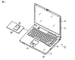
本実施形態においては、図1に示すように、パーソナルコンピュータ10から携帯型オーディオプレーヤ22に対して、近接無線通信によって音楽データを転送するシステム例にして説明する。なお、本発明の無線通信端末は、パーソナルコンピュータ10や携帯型オーディオプレーヤ22に限るものではなく、例えば携帯電話機、PDA(personal digital assistant)、携帯型オーディオ/ビデオプレイヤ、デジタルビデオカメラ、携帯型カーナビゲーション装置など、プログラムを実行するプロセッサが搭載された機器であれば良い。
In the present embodiment, as shown in FIG. 1, a system example in which music data is transferred from a
図1に示すパーソナルコンピュータ10は、ディスプレイユニットを開いた状態を示している。パーソナルコンピュータ10は、コンピュータ本体11と、ディスプレイユニット14とから構成されている。ディスプレイユニット14には、LCD(Liquid Crystal Display)14から構成される表示装置が組み込まれている。
The
ディスプレイユニット14は、コンピュータ本体11に対し、コンピュータ本体11の上面が露出される開放位置とコンピュータ本体11の上面を覆う閉塞位置との間を回動自在に取り付けられている。コンピュータ本体11は薄い箱形の筐体を有しており、その上面にはキーボード13、パワーオン/パワーオフするためのパワーボタン、入力操作パネル、タッチパッド16、及びスピーカなどが配置されている。
The
また、パーソナルコンピュータ10には、近接無線通信を行うことが可能なパッド形式の無線通信装置20が、例えばUSB(Universal Serial Bus)を介して接続されている。パーソナルコンピュータ10は、無線通信装置20に近接無線通信端末である携帯型オーディオプレーヤ22が載置(近接)されることにより、無線通信装置20を通じて携帯型オーディオプレーヤ22との間でデータ送信を実行する。
In addition, a pad-type
無線通信装置20には、上面部にアンテナ(図示せず)が配置されている。従って、携帯型オーディオプレーヤ22は、自機器に設けられた近接無線通信用アンテナ34が、無線通信装置20のアンテナ位置に近接されることによって安定したデータ通信が可能となる。本実施形態の携帯型オーディオプレーヤ22は、無線通信装置20に一度近接させることにより、安定した通信が可能となる位置の方向をユーザに提示することができる。ユーザは、携帯型オーディオプレーヤ22により提示される方向に移動させて、最良の位置で携帯型オーディオプレーヤ22を図1に示すようにして載置することで、大量のデータを効率よく転送可能な状態を維持させることができる。
In the
図2は、携帯型オーディオプレーヤ22の機能構成を示すブロック図である。
図2に示すように、携帯型オーディオプレーヤ22には、制御部30、表示部31、入力部32、データ格納部33、近接無線通信用アンテナ34、無線通信部35、通信品質検出部36、及び移動センサ部37が設けられている。
FIG. 2 is a block diagram showing a functional configuration of the
As shown in FIG. 2, the
制御部30は、プロセッサ(CPU)やメモリ等から構成されるもので、携帯型オーディオプレーヤ22の全体の制御を司る。制御部30は、各種プログラムをプロセッサにより実行することにより各種処理機能を実現する。本実施形態では、オーディオプレーヤとしての処理機能の他に、近接無線通信制御、近接無線通信の通信品質がより良好となる場所への移動を指示するための移動方向表示処理機能を実現する。移動方向表示処理では、移動センサ部37及び通信品質検出部36により検出されたデータをもとにして、より通信品質が良好となる位置の方向を示す表示を行う。
The
表示部31は、制御部30の制御のもとで、ディスプレイにおいて各種の情報を表示する。表示部31は、近接無線通信によってデータ転送を実行する場合には、制御部30により実行される移動方向表示処理により、何れの方向に携帯型オーディオプレーヤ22を移動させると、通信品質が良好(高速通信ができるか)に関する情報が表示される。
The
入力部32は、携帯型オーディオプレーヤ22に対して、ユーザがデータの入力や各種処理の実行を指示したりするために使用される。具体的にはボタンやキーボード等である。
The
データ格納部33は、携帯型オーディオプレーヤ22により扱われる各種のデータを格納するために使用される。具体的にはROM,RAM,HDD等により構成されている。データ格納部33には、例えばパーソナルコンピュータ10から受信された音楽データなどの再生コンテンツデータ等も含まれている。また、移動方向表示処理では、携帯型オーディオプレーヤ22を無線通信装置20に近接することにより通信品質検出部36によって検出される通信品質データや、移動センサ部37により検出される携帯型オーディオプレーヤ22の動きを示すデータ、また通信品質検出部36や移動センサ部37により検出されるデータをもとに算出された、例えば携帯型オーディオプレーヤ22の現在の位置と無線通信装置20との通信品質が良好となる位置(後述する仮想コア)との相対関係を示すデータなどが一時的に格納される。
The
通信品質検出部36は、無線通信部35が無線通信装置20との通信が可能となった場合に、近接無線通信用アンテナ34により受信された電波強度(受信強度)や通信中の無線の品質(通信レート)などの通信品質を表すデータを検知する。
When the
移動センサ部37は、携帯型オーディオプレーヤ22の動きを検出するためのセンサである。移動センサ部37は、例えば携帯型オーディオプレーヤ22の位置が変化することにより変化する加速度を検出する加速度センサ37aや、各軸(例えばx,y,z)の角度変位を検出するジャイロセンサ37bなどを含む。移動センサ部37は、加速度センサ37a及びジャイロセンサ37bにより時系列的に検出された動きの変化を示すデータをもとに、自端末の位置、変化量、移動方向を算出する。
The movement sensor unit 37 is a sensor for detecting the movement of the
無線通信部35は、無線通信装置20との間で近接無線通信を行う。具体的にはNFCや3.1GHz〜10.6GHzの周波数帯を使用するUWB、60GHz帯を使用するミリ波等による無線通信を実行する。
The
次に、本実施形態における携帯型オーディオプレーヤ22(近接無線通信端末)の移動方向表示処理について、図3に示すフローチャートを参照しながら説明する。図4及び図5は、携帯型オーディオプレーヤ22を無線通信装置20の通信品質が良好となる位置に載置するための操作例を示す図である。ここでは、例えば携帯型オーディオプレーヤ22において、データ転送の設定が行われている場合に、移動方向表示処理が実行される。
Next, the moving direction display processing of the portable audio player 22 (proximity wireless communication terminal) in this embodiment will be described with reference to the flowchart shown in FIG. 4 and 5 are diagrams illustrating an example of an operation for placing the
図4及び図5において、円で示す範囲は、近接無線通信可能な範囲101を表している。中心106に近いほど電波強度が強く、かつ、物理層における通信可能な通信レートが高い状況を表している。
4 and 5, a range indicated by a circle represents a
携帯型オーディオプレーヤ22において通信品質が良好となる方向を表示させるためには、ユーザは、例えば図4に示す軌跡102のようにして携帯型オーディオプレーヤ22を移動させて、一度、無線通信装置20との近接無線通信可能な範囲101を通過させる。
In order to display the direction in which the communication quality is good in the
近接無線通信可能な場所で軌跡102のように移動されることにより、携帯型オーディオプレーヤ22の制御部30は、近接無線通信可能な範囲101に到達した時点で、無線通信部35あるいは通信品質検出部36によって近接無線通信が可能な状態となったことを判別する(ステップA1)。例えば、図3における近接無線通信可能な範囲101との境界ポイント103aにおいて、無線通信部35により電波強度が変化した、もしくは無線通信部35により通信レートが変化したことが検出される。
The
制御部30は、境界ポイント103aにおける移動センサ部37により検出される位置と移動方向を検出する(ステップA2)。それ以降、制御部30は、境界ポイント103aを基準位置とした現在位置と各位置における移動方向を検出すると共に、電波強度(あるいは通信レート)の向上あるいは減少の変化量を検出する(ステップA3)。
The
そして、電波強度(あるいは通信レート)の向上/減少の変化量、携帯型オーディオプレーヤ22の現在の位置と移動方向をデータ格納部33に記録する(ステップA4)。 Then, the amount of change in the radio field intensity (or communication rate) is recorded in the data storage unit 33 (step A4).
そして、各位置における移動方向と変化量をもとにしたベクトル和により、通信品質が良好となり通信が安定することが想定される位置である仮想コア104の位置を算出する(ステップA5)。
Then, based on the vector sum based on the moving direction and the amount of change at each position, the position of the
例えば、位置の変化に伴って電波強度(あるいは通信レート)が向上している場合には、その時の移動方向に中心106があるものと仮定することができ、複数の異なる位置のそれぞれにおいて検出される、電波強度(あるいは通信レート)の向上/減少の変化量と移動方向をもとにしたベクトル和により、仮想コア104の位置を算出することができる。
For example, when the radio wave intensity (or communication rate) is improved with the change in position, it can be assumed that the
制御部30は、境界ポイント103aを基準とした現在位置からの、前述のようにして算出された仮想コア104の位置への方向を示す表示を行う。例えば、表示部31によってディスプレイに方向を示す矢印を表示する。なお、表示形態は矢印に限定されるものではなく、方向がユーザに認識できれば任意の表示形態を用いることができる。
The
携帯型オーディオプレーヤ22が近接無線通信可能な範囲101にある場合には(ステップA8、Yes)、制御部30は、各位置において検出される電波強度(あるいは通信レート)の向上/減少の変化量、携帯型オーディオプレーヤ22の移動方向をもとに求められるベクトル和により、仮想コア104の位置を算出し、現在位置から仮想コア104の方向を基づいて表示部31によって表示させる(ステップA2〜A8)。
When the
なお、制御部30は、軌跡102に沿って移動するのに伴って、電波強度もしくは通信レートが、予め設定された基準値に変化した境界ポイント103b,103c,103dで検出された、電波強度(あるいは通信レート)の向上/減少の変化量と移動方向をもとに仮想コア104の位置を算出し、現在位置から仮想コア104への方向を示す表示をすることができる。
The
また、仮想コア104の位置については、変化ポイント103a〜103dを検出する度に算出するようにしてもよい。ユーザが、仮想コア104を目指して携帯型オーディオプレーヤ22を移動させて行くにつれて変化ポイントを複数検出し、各変化ポイントにおけるベクトルを含むベクトル和を算出することで、仮想コア104の位置精度を向上させて行くことができる。
Further, the position of the
また、制御部30は、近接無線通信が不可能な状態となったことが、無線通信部35により検出される電波強度、あるいは通信品質検出部36により検出される通信レートをもとに判別されると(ステップA8、No)、近接無線通信が不可能となった境界ポイント103d(あるいはその直前)に検出された現在位置を基準として、移動センサ部37により検出されるデータをもとにして現在位置を算出すると共に、移動方向を検出する(ステップA9)。
The
制御部30は、境界ポイント103dにおいて算出された仮想コア104に対する現在位置からの方向を、図3に示すようにして、表示部31において表示させる(ステップA10)。
The
制御部30は、近接無線通信可能な範囲101の外においても、携帯型オーディオプレーヤ22が移動されることに変化する現在位置と仮想コア104との相対関係をユーザに提示する(ステップA8〜A10)。
The
なお、図5に示すように、携帯型オーディオプレーヤ22を仮想コア104の方向へ移動させることにより、携帯型オーディオプレーヤ22の現在位置と仮想コア104との相対的な関係、すなわち両者の距離が変化していくことを算出できる。制御部30は、この相対的な関係(距離)に応じて、図5に示す携帯型オーディオプレーヤ22a,22b,22cのように、矢印の長さを両者の距離が短くなるに従って短くなるように表示する(ステップA10)。これにより、ユーザは、仮想コア104への方向を示す表示から仮想コア104との位置関係(近い/遠い)についても認識することが可能となる。
As shown in FIG. 5, by moving the
なお、ステップA10においては、前述のようにして、仮想コア104と携帯型オーディオプレーヤ22の現在位置との距離に応じて表示形態(矢印の長さ)を変化させても良いし、電波強度あるいは通信レートに応じて表示形態を変更するようにしても良い。
In step A10, as described above, the display form (the length of the arrow) may be changed according to the distance between the
特に、最良の通信品質が得られている位置にある場合(仮想コア104と現在位置とが一致する場合)には、図5の携帯型オーディオプレーヤ22cに示すような特別な表示形態とすることで、ユーザに対して、携帯型オーディオプレーヤ22を載置すべき位置を明示することも可能である。
In particular, when it is in a position where the best communication quality is obtained (when the
なお、制御部30は、データ転送が終了したことが判別されると、移動方向表示処理を終了する(ステップA7,A11、Yes)。
When it is determined that the data transfer is completed, the
このようにして、本実施形態では、携帯型オーディオプレーヤ22を無線通信装置20の近接無線通信可能な範囲101に一度通過させることで、通信品質が現在の位置よりも優れる(好ましくは通信品質が最良となることが想定される)位置仮想コア104の位置を算出すると共に、移動に伴って移動センサ部37により検出されるデータをもとに現在位置を算出して、現在位置から仮想コア104への方向を示す表示をすることができる。ユーザは、この表示を参照して携帯型オーディオプレーヤ22を移動させて、通信品質が現在の位置よりも優れる位置に載置することができる。
In this way, in this embodiment, the
なお、前述した説明では、パーソナルコンピュータ10に接続された無線通信装置20と携帯型オーディオプレーヤ22との間で近接無線通信を行う場合を例にしているが、パーソナルコンピュータ10に近接無線通信機能を搭載することで、パーソナルコンピュータ10と携帯型オーディオプレーヤ22との間で、直接、近接無線通信を行うことができる。この場合、パーソナルコンピュータ10には、例えば図1に示すように、コンピュータ本体11の上面に設けられたパームレストにおいて、近接無線通信用のアンテナ24が実装されるものとする。携帯型オーディオプレーヤ22は、アンテナ24に近接させることで、通信品質が現在の位置よりも優れる(通信品質が最良となる)アンテナ24の位置を示す方向を表示部31において表示する。
In the above description, the case where close proximity wireless communication is performed between the
また、前述した説明では、図4及び図5に示すように、携帯型オーディオプレーヤ22に設けられた表示部31(ディスプレイ)に仮想コア104との相対関係を表す矢印等を提示するものとしているが他の提示形態、例えばLED(Light Emitting Diode)などのランプを用いたりしても良い。
Further, in the above description, as shown in FIGS. 4 and 5, an arrow indicating a relative relationship with the
また、本発明は、上記実施形態そのままに限定されるものではなく、実施段階ではその要旨を逸脱しない範囲で構成要素を変形して具体化できる。また、上記実施形態に開示されている複数の構成要素の適宜な組み合わせにより種々の発明を形成できる。例えば、実施形態に示される全構成要素から幾つかの構成要素を削除してもよい。更に、異なる実施形態に構成要素を適宜組み合わせてもよい。 Further, the present invention is not limited to the above-described embodiments as they are, and can be embodied by modifying the constituent elements without departing from the scope of the invention in the implementation stage. In addition, various inventions can be formed by appropriately combining a plurality of components disclosed in the embodiment. For example, some components may be deleted from all the components shown in the embodiment. Furthermore, you may combine a component suitably in different embodiment.
また、前述した実施の形態において記載した処理は、コンピュータに実行させることのできるプログラムとして、例えば磁気ディスク(フレキシブルディスク、ハードディスク等)、光ディスク(CD−ROM、DVD等)、半導体メモリなどの記録媒体に書き込んで各種装置に提供することができる。また、通信媒体により伝送して各種装置に提供することも可能である。コンピュータは、記録媒体に記録されたプログラムを読み込み、または通信媒体を介してプログラムを受信し、このプログラムによって動作が制御されることにより、上述した処理を実行する。 Further, the processing described in the above-described embodiment is a recording medium such as a magnetic disk (flexible disk, hard disk, etc.), optical disk (CD-ROM, DVD, etc.), semiconductor memory, etc., as a program that can be executed by a computer. And can be provided to various devices. It is also possible to transmit to a variety of devices by transmitting via a communication medium. The computer reads the program recorded on the recording medium or receives the program via the communication medium, and the operation is controlled by this program, thereby executing the above-described processing.
10…パーソナルコンピュータ、20…無線通信装置、22…携帯型オーディオプレーヤ、30…制御部、31…表示部、32…入力部、33…データ格納部、34…近接無線通信用アンテナ、35…無線通信部、36…通信品質検出部、37…移動センサ部、37a…加速度センサ、37b…ジャイロセンサ。
DESCRIPTION OF
Claims (4)
前記近接無線通信における通信品質を検出する通信品質検出手段と、
自端末の動きを検出する移動検出手段と、
前記移動検出手段により検出された動きの変化をもとに自端末の位置を算出する算出手段と、
前記算出手段により算出された位置と前記通信品質検出手段により前記位置において検出された通信品質をもとに、通信品質が現在の位置よりも優れる位置を算出する第1の位置算出手段と、
前記第1の位置算出手段により算出された位置と前記算出手段により算出された現在の位置との相対関係をユーザに提示する提示手段と
を具備したことを特徴とする無線通信端末。 Wireless communication means for performing proximity wireless communication with other electronic devices;
Communication quality detection means for detecting communication quality in the proximity wireless communication;
Movement detection means for detecting the movement of the terminal itself;
Calculation means for calculating the position of the terminal based on a change in movement detected by the movement detection means;
Based on the position calculated by the calculating means and the communication quality detected at the position by the communication quality detecting means, a first position calculating means for calculating a position where the communication quality is superior to the current position;
A wireless communication terminal comprising: a presenting means for presenting a user with a relative relationship between the position calculated by the first position calculating means and the current position calculated by the calculating means.
前記提示手段は、前記第2の位置算出手段により算出された位置と前記算出手段により算出された現在の位置との相対関係をユーザに提示することを特徴とする請求項1記載の無線通信端末。 Based on the position at which the wireless communication means is disconnected and the position when the wireless communication means is disconnected as a reference, a position with better communication quality than the current position is calculated based on the position calculated by the calculating means, the amount of change, and the moving direction. A second position calculating means for
The wireless communication terminal according to claim 1, wherein the presenting unit presents a user with a relative relationship between the position calculated by the second position calculating unit and the current position calculated by the calculating unit. .
Priority Applications (1)
| Application Number | Priority Date | Filing Date | Title |
|---|---|---|---|
| JP2008289024A JP2010118773A (en) | 2008-11-11 | 2008-11-11 | Wireless communication terminal |
Applications Claiming Priority (1)
| Application Number | Priority Date | Filing Date | Title |
|---|---|---|---|
| JP2008289024A JP2010118773A (en) | 2008-11-11 | 2008-11-11 | Wireless communication terminal |
Publications (2)
| Publication Number | Publication Date |
|---|---|
| JP2010118773A true JP2010118773A (en) | 2010-05-27 |
| JP2010118773A5 JP2010118773A5 (en) | 2011-04-07 |
Family
ID=42306159
Family Applications (1)
| Application Number | Title | Priority Date | Filing Date |
|---|---|---|---|
| JP2008289024A Pending JP2010118773A (en) | 2008-11-11 | 2008-11-11 | Wireless communication terminal |
Country Status (1)
| Country | Link |
|---|---|
| JP (1) | JP2010118773A (en) |
Cited By (7)
| Publication number | Priority date | Publication date | Assignee | Title |
|---|---|---|---|---|
| JP2012169752A (en) * | 2011-02-10 | 2012-09-06 | Sony Corp | Proximity communication device, display control method, and program |
| JP2012208771A (en) * | 2011-03-30 | 2012-10-25 | Felica Networks Inc | Communication terminal, communication method, and program |
| JP2014519763A (en) * | 2011-05-31 | 2014-08-14 | クアルコム,インコーポレイテッド | Method and apparatus for improving NFC activation and data exchange reporting mechanism |
| JP2015504273A (en) * | 2011-12-01 | 2015-02-05 | コーニンクレッカ フィリップス エヌ ヴェ | Method for guiding a user of a wireless device to establish an optimal wireless direct link to another wireless device, wireless device and wireless communication system |
| CN105517041A (en) * | 2016-01-06 | 2016-04-20 | 广东欧珀移动通信有限公司 | Communication direction indicating method and user equipment |
| CN106210246A (en) * | 2015-05-05 | 2016-12-07 | 腾讯科技(深圳)有限公司 | A kind of call control method and device |
| JP2017034635A (en) * | 2015-08-06 | 2017-02-09 | パナソニックIpマネジメント株式会社 | Terminal device, base station device, radio communication system and information notifying method |
Citations (3)
| Publication number | Priority date | Publication date | Assignee | Title |
|---|---|---|---|---|
| JP2002168647A (en) * | 2000-11-29 | 2002-06-14 | Ntt Docomo Inc | Direction presentation method and portable terminal |
| JP2003152621A (en) * | 2001-11-12 | 2003-05-23 | Seiko Epson Corp | Radio communication apparatus and electronic equipment |
| JP2004354351A (en) * | 2003-05-30 | 2004-12-16 | Sharp Corp | Radio wave transmitter search system, cellular phone communication terminal apparatus, and radio wave transmitter search method by radio wave transmitter search system |
-
2008
- 2008-11-11 JP JP2008289024A patent/JP2010118773A/en active Pending
Patent Citations (3)
| Publication number | Priority date | Publication date | Assignee | Title |
|---|---|---|---|---|
| JP2002168647A (en) * | 2000-11-29 | 2002-06-14 | Ntt Docomo Inc | Direction presentation method and portable terminal |
| JP2003152621A (en) * | 2001-11-12 | 2003-05-23 | Seiko Epson Corp | Radio communication apparatus and electronic equipment |
| JP2004354351A (en) * | 2003-05-30 | 2004-12-16 | Sharp Corp | Radio wave transmitter search system, cellular phone communication terminal apparatus, and radio wave transmitter search method by radio wave transmitter search system |
Cited By (10)
| Publication number | Priority date | Publication date | Assignee | Title |
|---|---|---|---|---|
| JP2012169752A (en) * | 2011-02-10 | 2012-09-06 | Sony Corp | Proximity communication device, display control method, and program |
| JP2012208771A (en) * | 2011-03-30 | 2012-10-25 | Felica Networks Inc | Communication terminal, communication method, and program |
| JP2014519763A (en) * | 2011-05-31 | 2014-08-14 | クアルコム,インコーポレイテッド | Method and apparatus for improving NFC activation and data exchange reporting mechanism |
| JP2015222994A (en) * | 2011-05-31 | 2015-12-10 | クアルコム,インコーポレイテッド | Methods and apparatus for improving nfc activation and data exchange reporting mechanisms |
| US9735834B2 (en) | 2011-05-31 | 2017-08-15 | Qualcomm Incorporated | Methods and apparatus for improving NFC activation and data exchange reporting mechanisms |
| JP2015504273A (en) * | 2011-12-01 | 2015-02-05 | コーニンクレッカ フィリップス エヌ ヴェ | Method for guiding a user of a wireless device to establish an optimal wireless direct link to another wireless device, wireless device and wireless communication system |
| CN106210246A (en) * | 2015-05-05 | 2016-12-07 | 腾讯科技(深圳)有限公司 | A kind of call control method and device |
| JP2017034635A (en) * | 2015-08-06 | 2017-02-09 | パナソニックIpマネジメント株式会社 | Terminal device, base station device, radio communication system and information notifying method |
| CN105517041A (en) * | 2016-01-06 | 2016-04-20 | 广东欧珀移动通信有限公司 | Communication direction indicating method and user equipment |
| CN105517041B (en) * | 2016-01-06 | 2018-01-19 | 广东欧珀移动通信有限公司 | One kind call direction indicating method and user equipment |
Similar Documents
| Publication | Publication Date | Title |
|---|---|---|
| JP2010118773A (en) | Wireless communication terminal | |
| US8725213B2 (en) | Wireless communication device | |
| US10401982B2 (en) | Electronic device including input module | |
| US10467438B1 (en) | Proximity sensor algorithms to control transmit power of a user device after water immersion | |
| US20210092703A1 (en) | ELECTRONIC DEVICE FOR DETERMINING PATH OF LINE OF SIGHT (LoS) AND METHOD FOR THE SAME | |
| US8909139B2 (en) | Mobile wireless communications system including selectively coupled pair of discontinuous NFC circuit segments and related methods | |
| US9774362B1 (en) | Adaptive antenna tuning based on a sensed characteristic | |
| EP3072243B1 (en) | Object detection and characterization | |
| KR101607283B1 (en) | Mobile terminal and control method thereof | |
| CN108391058B (en) | Image capturing method, image capturing apparatus, electronic apparatus, and storage medium | |
| CN106060612A (en) | Video playing method and video playing device | |
| US20180038948A1 (en) | Ultrasound based configuration detection of a multipart electronic apparatus | |
| WO2017088631A1 (en) | Mobile terminal, increase/decrease adjusting method and apparatus therefor, and storage medium | |
| US11348490B1 (en) | Method of controlling display and electronic device supporting the same | |
| JP4528854B2 (en) | Electronic equipment, communication status output method | |
| CN109737938B (en) | Terminal device | |
| JP4922435B2 (en) | Electronic equipment, communication status output method | |
| WO2016068192A1 (en) | Electronic device, control method, and control program | |
| KR101495179B1 (en) | Mobile terminal and method for transmitting information | |
| CN112397453A (en) | Display panel and electronic equipment | |
| KR20090101541A (en) | Portable terminal for remote controling external electronic apparatus and method thereof | |
| CN108966266A (en) | Communication connecting method, device, electronic device and computer-readable medium | |
| KR102120449B1 (en) | Method for operating application and electronic device thereof | |
| JP2011160147A (en) | Communication device and communication control method | |
| US20240089584A1 (en) | Electronic device and operation method of electronic device |
Legal Events
| Date | Code | Title | Description |
|---|---|---|---|
| A521 | Written amendment |
Effective date: 20110218 Free format text: JAPANESE INTERMEDIATE CODE: A523 |
|
| A621 | Written request for application examination |
Effective date: 20110218 Free format text: JAPANESE INTERMEDIATE CODE: A621 |
|
| A977 | Report on retrieval |
Free format text: JAPANESE INTERMEDIATE CODE: A971007 Effective date: 20120815 |
|
| A131 | Notification of reasons for refusal |
Effective date: 20120821 Free format text: JAPANESE INTERMEDIATE CODE: A131 |
|
| A02 | Decision of refusal |
Free format text: JAPANESE INTERMEDIATE CODE: A02 Effective date: 20130108 |
|
| A521 | Written amendment |
Effective date: 20130201 Free format text: JAPANESE INTERMEDIATE CODE: A523 |