EP0829246B1 - Fauteuil roulant à propulsion électrique - Google Patents
Fauteuil roulant à propulsion électrique Download PDFInfo
- Publication number
- EP0829246B1 EP0829246B1 EP97115202A EP97115202A EP0829246B1 EP 0829246 B1 EP0829246 B1 EP 0829246B1 EP 97115202 A EP97115202 A EP 97115202A EP 97115202 A EP97115202 A EP 97115202A EP 0829246 B1 EP0829246 B1 EP 0829246B1
- Authority
- EP
- European Patent Office
- Prior art keywords
- wheelchair
- seat
- motor
- electrically driven
- battery
- Prior art date
- Legal status (The legal status is an assumption and is not a legal conclusion. Google has not performed a legal analysis and makes no representation as to the accuracy of the status listed.)
- Expired - Lifetime
Links
Images


Classifications
-
- A—HUMAN NECESSITIES
- A61—MEDICAL OR VETERINARY SCIENCE; HYGIENE
- A61G—TRANSPORT, PERSONAL CONVEYANCES, OR ACCOMMODATION SPECIALLY ADAPTED FOR PATIENTS OR DISABLED PERSONS; OPERATING TABLES OR CHAIRS; CHAIRS FOR DENTISTRY; FUNERAL DEVICES
- A61G5/00—Chairs or personal conveyances specially adapted for patients or disabled persons, e.g. wheelchairs
- A61G5/04—Chairs or personal conveyances specially adapted for patients or disabled persons, e.g. wheelchairs motor-driven
- A61G5/041—Chairs or personal conveyances specially adapted for patients or disabled persons, e.g. wheelchairs motor-driven having a specific drive-type
- A61G5/045—Rear wheel drive
-
- A—HUMAN NECESSITIES
- A61—MEDICAL OR VETERINARY SCIENCE; HYGIENE
- A61G—TRANSPORT, PERSONAL CONVEYANCES, OR ACCOMMODATION SPECIALLY ADAPTED FOR PATIENTS OR DISABLED PERSONS; OPERATING TABLES OR CHAIRS; CHAIRS FOR DENTISTRY; FUNERAL DEVICES
- A61G5/00—Chairs or personal conveyances specially adapted for patients or disabled persons, e.g. wheelchairs
- A61G5/04—Chairs or personal conveyances specially adapted for patients or disabled persons, e.g. wheelchairs motor-driven
- A61G5/048—Power-assistance activated by pushing on hand rim or on handlebar
-
- A—HUMAN NECESSITIES
- A61—MEDICAL OR VETERINARY SCIENCE; HYGIENE
- A61G—TRANSPORT, PERSONAL CONVEYANCES, OR ACCOMMODATION SPECIALLY ADAPTED FOR PATIENTS OR DISABLED PERSONS; OPERATING TABLES OR CHAIRS; CHAIRS FOR DENTISTRY; FUNERAL DEVICES
- A61G5/00—Chairs or personal conveyances specially adapted for patients or disabled persons, e.g. wheelchairs
- A61G5/10—Parts, details or accessories
- A61G5/1054—Large wheels, e.g. higher than the seat portion
-
- A—HUMAN NECESSITIES
- A61—MEDICAL OR VETERINARY SCIENCE; HYGIENE
- A61G—TRANSPORT, PERSONAL CONVEYANCES, OR ACCOMMODATION SPECIALLY ADAPTED FOR PATIENTS OR DISABLED PERSONS; OPERATING TABLES OR CHAIRS; CHAIRS FOR DENTISTRY; FUNERAL DEVICES
- A61G2203/00—General characteristics of devices
- A61G2203/30—General characteristics of devices characterised by sensor means
- A61G2203/38—General characteristics of devices characterised by sensor means for torque
-
- Y—GENERAL TAGGING OF NEW TECHNOLOGICAL DEVELOPMENTS; GENERAL TAGGING OF CROSS-SECTIONAL TECHNOLOGIES SPANNING OVER SEVERAL SECTIONS OF THE IPC; TECHNICAL SUBJECTS COVERED BY FORMER USPC CROSS-REFERENCE ART COLLECTIONS [XRACs] AND DIGESTS
- Y10—TECHNICAL SUBJECTS COVERED BY FORMER USPC
- Y10S—TECHNICAL SUBJECTS COVERED BY FORMER USPC CROSS-REFERENCE ART COLLECTIONS [XRACs] AND DIGESTS
- Y10S180/00—Motor vehicles
- Y10S180/907—Motorized wheelchairs
-
- Y—GENERAL TAGGING OF NEW TECHNOLOGICAL DEVELOPMENTS; GENERAL TAGGING OF CROSS-SECTIONAL TECHNOLOGIES SPANNING OVER SEVERAL SECTIONS OF THE IPC; TECHNICAL SUBJECTS COVERED BY FORMER USPC CROSS-REFERENCE ART COLLECTIONS [XRACs] AND DIGESTS
- Y10—TECHNICAL SUBJECTS COVERED BY FORMER USPC
- Y10S—TECHNICAL SUBJECTS COVERED BY FORMER USPC CROSS-REFERENCE ART COLLECTIONS [XRACs] AND DIGESTS
- Y10S297/00—Chairs and seats
- Y10S297/04—Wheelchair
Definitions
- the present invention relates to an electrically driven wheelchair.
- An electrically driven wheelchair according to the preamble of claim 1 is known from US-A-5 234 066.
- Electrically driven wheelchairs with manually rotated drive wheels with an assisted drive are well known.
- electrically driven wheelchairs are disclosed in Japanese Laid Open Patent Application No. Sho-51-100556, and Japanese Laid Open Patent Application No. Hei-8-117291. These wheelchairs can be folded in two along their width for transportation and storage.
- wheelchairs are known wherein the motor is housed within the hub of the drive wheel and when folding the left and right wheels are separated from the motor and frame.
- the wheelchair body frame contains electrical equipment including the battery which is both bulky and heavy. This separation when compared to the weight of the drive wheels is unbalanced due to the large difference in the weight distribution. Therefore, it is difficult for a user to load the heavy separated parts into a transportation vehicle, etc. Also, when assembling the wheelchair, as the drive wheel is first attached to the one side of the frame, after which, the remaining the one side of the frame, after which, the remaining wheel is then attached to the other side, the wheelchair frame tends to become unbalanced, again making it difficult for a user to assemble the wheelchair by the user.
- a fold-up type wheelchair with an electrical driving apparatus attached thereto is provided with a saccate box containing a battery mounted to the back side of a cloth seat as disclosed in Japanese Laid Open Patent Application No. Hei-7-313555.
- wheelchairs with an electrical driving apparatus attached including the wheelchairs disclosed in the related art are, on the whole, intended for indoor use. Therefore, it is necessary to give consideration to the protection of the electrical equipment from dirt and debris such as mud, flying stones and water, etc., when used out doors.
- the present invention is directed to an electrically driven wheelchair, with drive wheels driven by a battery powered motor, equipped with a wheelchair body frame and a seat.
- the drive wheels are supported by the wheelchair body frame and a housing is provided to house electrical equipment including the battery and control unit mounted to the seat base plate.
- the seat with an integrated. housing part is freely detachable from the wheelchair frame.
- the seat, drive wheel and drive force transmission device are supported by the wheelchair frame with a motor attached to the seat.
- the seat is freely detachable from the wheelchair frame.
- the motor can be freely connected or disconnected from the driving force transmission device.
- the motor is mounted to the seat. Further, the drive force transmission device is mounted to the wheelchair body frame so that when removing or replacing the seat, as the motor freely connects or disconnects from the drive force transmission device, the weight distribution of the seat and the wheelchair body frame is more balanced.
- the housing for a battery and a control unit, etc. provided on the under surface of a seat includes an opening portion for inserting and removing the battery which is located on the front part of the housing.
- the opening portion is fitted with an opening and closing lid.
- the battery is detachable freely in a forward direction in parallel with the base plate of the seat.
- the discharge terminal of the battery and the discharge connector of the motor connects or disconnects together with the detachment operation of the battery.
- the opening portion is provided on the front side, the removal operation of the battery does not interfere with members of the body, thereby enabling the housing to be located in a high position as close as possible to the seat.
- the internal electrical equipment is securely protected from splashed mud, flying stones and the impact of projections on the road during use of the wheelchair outdoors.
- the outward appearance of the wheelchair resembles that of a common, light, manually operated wheelchair rather than an electrically operated type.
- the opening part can be closed with the lid after installing the battery, making it possible to prevent rain water from entering the internal part of the housing through the opening part, thereby increasing the water resistance capability of the internal part housing the battery, control unit and other electrical equipment and in particular the area around the discharge connector. Consequently, increasing the protection of the battery and the control unit from dirt and projections and increasing the water resistance capability of the discharge connector, etc., has made the wheelchair suitable for use both indoors and outdoors.
- the detachment operation when replacing the battery, etc. is carried out in a location which can be reached by the user, allowing an unaided user to carry out the operation while seated, simplifying the removal and replacement process.
- the wheelchair with an electrical driving apparatus attached consists of a main frame 1 having a pair of left and right members extending obliquely to the rear, with caster wheels 2 fitted to each of the front end portions, and drive wheels 3 fitted to the rear portions.
- a hand rim 4 of a slightly smaller diameter and with the same center of rotation is attached to the outside of drive wheel 3.
- the hand rim 4 is constructed so as to be capable of being rotated manually or assist driven by the motor.
- a hub 3b of the drive wheel 3 is provided with spokes 3d. Spokes 4a of the hand rim 4 are mounted on a hub 4b of the hand rim.
- the assist quantity is determined by control unit 7 provided under a seat 6.
- the assist is based on the torque differential between the drive wheel 3 and the hand rim 4 which is detected by the torque sensor contained in hub 3b, which is omitted from the drawing.
- the assist is provided by a motor 5 powered by a battery 8.
- a housing 10 which houses the electrical equipment 7, 8 is formed on the bottom of seat 6.
- the housing 10 is housed within the rectangular space S surrounded by a seat rail 11 and on the front and back by cross members 12, 13.
- a freely folding back rest 9 folds down onto the seat 6.
- Seat rails 11 include a pair of left and right members extending almost parallel from front to back and are supported on the left and right side of a subframe 14 mounted sloping slightly upwardly towards the front so as to be almost overlapping with the upper parts of the left end right parts of mainframe when viewed from above.
- a cross member 13 extends across each of the end parts of the left and right seat rails 11.
- a rim part of the base plate 15 of seat 6 rests on frame members 11, 12, 13, by engaging pre-fitted engagement lugs made of rubber, etc., which are omitted from the drawings and mate with corresponding engagement holes 17, as illustrated in Fig. 4, formed on the upper surface of the aforementioned frame members.
- the seat 6 can be both supported and freely detachable from the frame.
- Upper part structure A includes the seat 6, back rest 9, seat rail 11, cross member 12, cross member 13, subframe 14, in addition to the motor 5, control unit 7 and battery 8, etc., and other electronic equipment housed in the housing 10.
- Lower part structure B includes the left and right portions of mainframe 1, front wheels 2, drive wheels 3, hand rims 4 and subrims 14, etc. Furthermore, the left and right portions of mainframe 1 can be freely folded together and connected as an integrated unit by link member 1a as illustrated in Fig. 3 and Fig. 4.
- connection between upper structure A and lower structure B occurs in a total of 3 locations; hinge part boss 9b of the back rest 9, the joint provided on the back end portion of the seat rail 11, and the motor 5.
- the hinge part boss 9b is provided with a cut off portion 9c.
- the upper end portion of stay support shaft 18a which protrudes inwardly towards the wheelchair body fits into the upper end portion of stay 18 which protrudes upwards from the back end of main frame 1.
- support shaft 13d protrudes outwardly from the upper end of stay 13c which protrudes upwardly almost parallel with stay 18 and fits into both left and right end portions of the cross member 13.
- Cut off part 9c when engaged with the support shaft 18a, prevents the seat 6 from being removed in a forward direction while the back rest 9 is in an upright position.
- support shaft 18a does not engage with the hinge boss 9b, enabling the seat 6 to be removed.
- Joint 13a is attached to both the left and right ends of cross member 13.
- the rear end portion of the seat rail 11 is connected to the front surface of the seat.
- Engaging pin 13b protrudes outwardly and is provided on the outside surface of the cross member 13.
- Engaging pin 13b by moving seat rail 11 of seat 6 resting on subframe 14 in a backwards and forwards direction, can be disengaged in a forward direction towards stay 18.
- the engaging pin 13b is freely detached along engaging grove 18b.
- Motor guide 13e to which motor 5 is suspended and supported through slider 5a, is provided on the rear surface of both the left and right ends of cross member 13.
- the motor 5, as shown in Figs. 5 and 6, moves freely along the width of the wheelchair body through slider 5a mounted on motor guide 13e.
- output axis 5b changes with the connection location, Fig. 5, and the disconnection location, Fig. 6.
- the movement of the motor 5 is operated by actuating lever 19, wire 19b connected to a revolving drum 19a operated by actuating lever 19 which is attached to the slicer 5a.
- backrest 9 is folded down onto seat 6, and, by operating the actuating lever 19, motor 5 is moved inwardly towards the body of the wheelchair, as shown in Fig. 6.
- hinge part boss 9b can be separated from stay 13c, and output axis 5b of motor 5 can be separated from axle stay 1b.
- engaging pin 13b can then be removed from the engaging groove 18b, separating the whole upper structure A from the lower section B.
- the upper structure A can be simply attached to the lower structure B.
- Fig. 7 shows a second embodiment wherein a mainframe 20 is formed in a loop shape for supporting a lower part 21 with front wheels 2 attached to front portions thereof and an upper part 22 provides a support part for the seat 6.
- An axle support stay 24 is provided on the corner parts of upper portion 22 and upper and lower portions 23, with an axle 3c supporting a hub 3b of a drive wheel 3.
- a torque sensor determines the torque differential manually applied to the hand rim. The torque sensor is contained inside the hub 3b.
- the left and right portions of main frame 20 can be freely folded up and joined together by an X-shaped link member 25.
- the housing 10 is formed in the bottom of the seat 6, in which the motor 5, control unit 7, battery 8, and other electrical equipment is housed.
- the transmission axle 26 is formed either in combination or independently of the output axis of the motor 5 and is connected to enable combined rotation.
- Seat 6 rests on the left and right portions of the upper part 22 of main frame 20.
- upper structure A and lower structure B are connected as one.
- the transmission axle 26, in the configuration of the previous embodiment, does not connect directly with the axle 3c. Namely, the transmission axle 26 does not use axle 3c as a drive shaft.
- the transmission axle 26 enables the drive rotation of hub 3b around the periphery of axle 3c.
- upper structure A and lower structure B have approximately the same weight distribution, enabling them to be separated both simply and speedily. Furthermore, common notation has been used for members common to the configuration of the previous embodiment.
- the wheelchair includes an electrical driving apparatus attached to a mainframe 101 with left end right pair portions sloping upwardly towards the rear.
- a caster 102 is mounted on each of the front end portions, and drive wheels 103 are mounted to the rear end portions.
- a hand rim 104 with a slightly smaller diameter and the same center of rotation is attached to the outside of each drive wheel.
- the drive wheels can either be rotated manually by the hand rim 104 or assisted to be driven by a motor.
- the assist quantity is determined by a control unit 107 mounted on the under side of seat 106 based on the torque differential between the drive wheel 103 and the hand rim 104 detected by the torque sensor, omitted from the drawings. Motor 105 then assists using electric power provided by a battery 108.
- a housing 110 is formed on the bottom part of seat 106 to house electrical equipment 107, 108.
- the housing 110 is contained within the rectangular space S surrounded by a seat rail 111 and cross members 112, 113 at the front and back.
- a free folding back rest 109 is mounted on the seat 106.
- Seat rails 111 include a pair of left and right members extending almost parallel from front to back which are supported on the left and right of a subframe 114 mounted sloping slightly upwardly towards the front so as to be almost overlapping with the upper parts of the left and right portions of the mainframe when viewed from above.
- a cross member 113 extends across each of the end parts of the left and right seat rails 111.
- bracket 111a which hangs downwardly and is bent inwardly towards the wheelchair body, is mounted on the front ends of the left and right seat rails 111 and a cross member 112 extends across the lower end parts of the left and right brackets 111a.
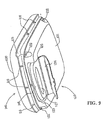
- a rim part of a base plate 115 of seat 106 rests on frame members 111, 112, 113 by engaging pre-fitted engagement lugs 116 made of rubber, etc. as illustrated in Fig. 9, to correspond with engagement holes 117 as illustrated in Fig. 12 formed on the upper surface of the frame members.
- the seat 106 can be both supported and be freely detachable from the frame.
- Fig. 8 is a side cross sectional view of seat 106.
- Fig. 9 is a perspective view showing seat 106 from the front on an angle from below. As shown in Figs. 8 and 9, the seat 106 is provided with a seating cushion 120 and the housing 110 is mounted to the under surface of the base plate 115.
- Base plate 115 is constructed from synthetic resin, metal, wood material or other suitable material.
- container-shaped housing cover 121 is attached by screws 122 at four corners.
- the housing cover 121 can be constructed from synthetic resin, metal, wood material or other suitable material but must be formed from a material of a sufficient relative hardness to withstand the impact of flying stones.
- the housing 110 is formed between the housing cover 121 and base plate 115.
- An open opening 123 is mounted to face forwardly to the front portion of the housing cover 121 and is provided with a freely opening and closing lid 124 fitted to the under side front part of the housing cover 121 by a hinge 125.
- a handle is mounted on the front portion of the lid 124.
- the handle can be freely detached from the surrounding housing cover 121 using a suitable engagement member.
- the thin type battery 108 can be removed and replaced freely into the housing 110 through the opening 123.
- an indent part 127 is formed on the front part of the battery 108.
- the battery 108 is supported by a guide plate 130 fixed to base plate 115 by a screw 131.
- the female terminal omitted from the drawings, which is formed on the back face of the back end part 128 of the battery 108 connects with the male discharge connector 133 supported by back end portion 132 of the same guide plate 130.
- these male and female parts may be reversed.
- Discharge connector 133 is connected to the control unit 107 by a conductor 134.
- the battery 108 supplies electric power to control unit 107.
- Control unit 107 is attached to base plate 115 by screw 135.
- Control unit 107 is constructed from well known micro computers, etc. Based on the detected value of the aforementioned torque sensor, the control unit 107 provides assisted drive by utilizing the motor 105 according to a determined amount of required assisted drive.
- An output conductor 136 for this purpose extends to the motor 105.
- the removal operation of the battery 108 is carried out in a forward direction parallel to base plate 115, it is possible to use the relatively hard and structurally sound base plate 115 as a guide member, making it unnecessary to look into the housing 110 while performing the operation.
- the provision of guide plate 130 ensures accurate guidance. Also, as the housing is in a position which can be reached by the wheelchair user, Fig. 10, the operation can be performed while seated, enabling the wheelchair user to perform the battery detachment operation him/herself with ease.
- the battery detachment operation has been simplified and expedited as the discharge connector 133 is rigidly fixed to base plate 115, and the discharge terminal of the battery 108 and the discharge connector 133 of the control unit 107 connects and disconnects together with the detachment operation of the battery 108.
- housing 110 has been formed by attaching housing cover 121 to the under side of base plate 115, and by fitting the opening part 123 to the front side, the removal and replacement operation of battery 108 is performed in a forward direction, making it unnecessary to interfere with the wheelchair body members.
- the housing 110 has been located in a high position as close as possible to seat 106, making it difficult for flicked-up mud, stones or road surface projections, etc., to collide with the housing while operating out of doors.
- housing cover 121 is also thin which enables its fitted position to housing 110 to be further raised.
- electrical equipment including the battery 108, control unit 107, discharge connector 133 and conductor 132, 136, etc., are further protected from collisions from flying stones, etc.. From an outward appearance, the wheelchair resembles that of a common manually operated light wheelchair without an assist drive.
- lid 124 allows opening portion 123 to be closed following the replacement of the battery 108 preventing rainwater from entering the inside part of the housing cover 121 from the opening part 123.
- improved water resistance capacity of the electrical equipment housed inside including battery 108 and control unit 107, etc. is achieved, especially with regard to the area surrounding the discharge connector 133. Consequently, by improving the protection capacity of the electrical equipment including the battery 108 and control unit 107 from dirt and any impact and by improving the water resistance capacity of the discharge connector 133, etc., the wheelchair according to the present invention is sufficiently suited for outdoor use.
- a wheelchair includes an upper structure A and lower structure B which can be freely assembled and separated.
- Upper structure A includes a seat, back rest, seat rail, cross member, cross member and a subframe.
- Electrical equipment including a control unit and battery, etc., is housed inside a housing mounted on the bottom part of seat.
- a motor is supported under the cross member.
- the lower structure includes the left and right pair portions of a main frame, front wheels, drive wheels and hand rims.
- Upper structure A can be separated and removed from lower structure B by folding down the back rest and removing the upper structure A.
- the output axis is removed from the axle stay by moving the motor towards the center of the wheelchair body.
- a housing cover is fitted to the rear face of a base plate provided on a seat of the wheelchair.
- a freely opened and closed lid is provided for the opening provided on the front portion.
- a guide plate is provided on the front of the housing formed by the base plate and the housing cover.
- a control unit is fitted to the rear. When the lid is opened and battery is inserted from the front into housing cover and guided and supported by the guide plate, the battery simultaneously connects with the discharge connector at the side of control unit.
Landscapes
- Health & Medical Sciences (AREA)
- Life Sciences & Earth Sciences (AREA)
- Animal Behavior & Ethology (AREA)
- General Health & Medical Sciences (AREA)
- Public Health (AREA)
- Veterinary Medicine (AREA)
- Handcart (AREA)
- Arrangement Or Mounting Of Propulsion Units For Vehicles (AREA)
Claims (13)
- Fauteuil roulant à propulsion électrique, comportant :caractérisé en ce queun châssis de corps de fauteuil roulant pliable (1 ; 20 ; 101),un siège (6 ; 106) monté sur ledit châssis de fauteuil roulant (1 ; 20 ; 101),un dispositif de propulsion électrique (5, 7,8 ; 105, 107, 108), comprenant un moteur (5 ; 105) entraíné par batterie (8 ; 108), ledit dispositif de propulsion électrique (5, 7, 8 ; 105, 107, 108) étant monté de manière amovible par rapport audit châssis de corps de fauteuil roulant (1 ; 20 ; 101) pour fournir une propulsion assistée des roues motrices (3 ; 103) supportées pour leur rotation sur le châssis de corps de fauteuil roulant (1 ; 20 ; 101),
ledit dispositif de propulsion électrique (5, 7, 8 ; 105, 107, 108) et ledit siège (6 ; 106) sont montés l'un sur l'autre, de telle sorte qu'ils sont montés de manière amovible par rapport audit châssis de corps de fauteuil roulant (1 ; 20 ; 101) pour séparer de manière sélective et ensemble ledit siège (6 ; 106) et ledit dispositif de propulsion électrique (5, 7, 8 ; 105, 107, 108) du châssis de fauteuil roulant (1 ; 20 ; 101). - Fauteuil roulant à propulsion électrique selon la revendication 1, dans lequel ledit dispositif de propulsion électrique (5, 7, 8 ; 105, 107, 108) comporte de plus une unité de commande (7 ; 107) pour commander l'actionnement dudit moteur (5 ; 105) entraíné par batterie (8 ; 108).
- Fauteuil roulant à propulsion électrique selon la revendication 1 ou 2, comportant de plus un dispositif de transmission de force motrice (1b, 3a, 3b) supporté sur ledit châssis de fauteuil roulant (1) ; dans lequel ledit moteur (5) peut venir en prise avec ledit dispositif de transmission de force motrice (1b, 3a, 3b), et ledit moteur (5) est librement séparable dudit châssis (1) lors du retrait dudit siège (6), et ledit moteur (5) est connecté ou déconnecté librement de manière sélective au dispositif de transmission de force motrice (1b, 3a, 3b).
- Fauteuil roulant à propulsion électrique selon la revendication 1, et comportant de plus un boítier (10 ; 110) incluant la batterie (8 ; 108) et l'unité de commande (7 ; 107), ledit boítier (10 ; 110) étant monté sur une surface inférieure dudit siège (6 ; 106).
- Fauteuil roulant à propulsion électrique selon la revendication 4, dans lequel ledit boítier (110) comporte de plus une partie d'ouverture (123) pour insertion et enlèvement de la batterie (108) positionnée sur la partie avant du boítier (110).
- Fauteuil roulant à propulsion électrique selon la revendication 4, dans lequel la partie d'ouverture (123) est munie d'un couvercle d'ouverture et de fermeture (124).
- Fauteuil roulant à propulsion électrique selon la revendication 4, dans lequel la batterie (108) est librement amovible vers l'avant par rapport au siège (106) du fauteuil roulant, et parallèlement à une plaque de base (115) du siège (106)
- Fauteuil roulant à propulsion électrique selon la revendication 4, une borne de décharge de la batterie (108) et un connecteur de décharge (133) du moteur (105) étant connectés ou déconnectés en même temps lorsque la batterie (108) est fixée sur le boítier (110), ou enlevée de celui-ci.
- Fauteuil roulant à propulsion électrique selon l'une quelconque des revendications 1 à 8, et comportant de plus des pattes de mise en prise (116) montées sur ledit siège (106), destinées à venir en prise avec des ouvertures (117) situées dans ledit fauteuil roulant pour le montage dudit siège (106) sur celui-ci.
- Fauteuil roulant à propulsion électrique selon la revendication 9, et comportant de plus un levier d'actionnement (19 ; 119) connecté de manière opérationnelle au moteur (5 ; 105), pour connecter de manière sélective un arbre d'entraínement (5b) du moteur (5 ; 105) aux roues motrices (3 ; 103) du fauteuil roulant, et libérer de manière sélective l'arbre d'entraínement (5b) du moteur (5 ; 105) des roues motrices (3 ; 103) pour permettre audit boítier (10 ; 110) d'être retiré du châssis de fauteuil roulant (1 ; 20 ; 101).
- Fauteuil roulant à propulsion électrique selon l'une quelconque des revendications précédentes, dans lequel l'arbre d'entraínement (5b) est connecté à un renfort d'essieu (1b) fixé sur les roues motrices (3 ; 103) pour assurer la rotation de celles-ci.
- Fauteuil roulant à propulsion électrique selon la revendication 1, dans lequel l'arbre d'entraínement (26) est connecté directement à un moyeu d'essieu (3b) de la roue entraínée (3) pour assurer une connexion directe entre l'arbre d'entraínement (26) dudit moteur (5) et le moyeu d'essieu (3b) de la roue entraínée (3).
- Fauteuil roulant à propulsion électrique selon la revendication 1, dans lequel ledit siège (6) comporte un arbre de support (13d) s'étendant à partir de celui-ci, pour son appariement avec un renfort fixé sur ledit châssis de fauteuil roulant (1) pour le montage dudit siège (6) par rapport audit châssis de fauteuil roulant (1).
Applications Claiming Priority (6)
| Application Number | Priority Date | Filing Date | Title |
|---|---|---|---|
| JP241782/96 | 1996-09-12 | ||
| JP24178196A JP3609214B2 (ja) | 1996-09-12 | 1996-09-12 | 電動装置付車椅子 |
| JP24178296 | 1996-09-12 | ||
| JP24178196 | 1996-09-12 | ||
| JP8241782A JPH1085269A (ja) | 1996-09-12 | 1996-09-12 | 電動車椅子 |
| JP241781/96 | 1996-09-12 |
Publications (3)
| Publication Number | Publication Date |
|---|---|
| EP0829246A2 EP0829246A2 (fr) | 1998-03-18 |
| EP0829246A3 EP0829246A3 (fr) | 1998-12-16 |
| EP0829246B1 true EP0829246B1 (fr) | 2002-10-09 |
Family
ID=26535442
Family Applications (1)
| Application Number | Title | Priority Date | Filing Date |
|---|---|---|---|
| EP97115202A Expired - Lifetime EP0829246B1 (fr) | 1996-09-12 | 1997-09-02 | Fauteuil roulant à propulsion électrique |
Country Status (3)
| Country | Link |
|---|---|
| US (1) | US6050356A (fr) |
| EP (1) | EP0829246B1 (fr) |
| DE (1) | DE69716209T2 (fr) |
Families Citing this family (41)
| Publication number | Priority date | Publication date | Assignee | Title |
|---|---|---|---|---|
| US5806111A (en) | 1996-04-12 | 1998-09-15 | Hill-Rom, Inc. | Stretcher controls |
| US6405816B1 (en) | 1999-06-03 | 2002-06-18 | Deka Products Limited Partnership | Mechanical improvements to a personal vehicle |
| US6330926B1 (en) * | 1999-09-15 | 2001-12-18 | Hill-Rom Services, Inc. | Stretcher having a motorized wheel |
| US6772850B1 (en) | 2000-01-21 | 2004-08-10 | Stryker Corporation | Power assisted wheeled carriage |
| US6371228B1 (en) * | 2000-02-12 | 2002-04-16 | Royce H. Husted | Stable powered tricycle with traction steering |
| US6273212B1 (en) * | 2000-02-12 | 2001-08-14 | Royce H. Husted | Lightweight maneuverable power chair |
| CN1899233A (zh) | 2000-05-11 | 2007-01-24 | 希尔-罗姆服务股份有限公司 | 病人支撑台的机动牵引装置 |
| US7014000B2 (en) | 2000-05-11 | 2006-03-21 | Hill-Rom Services, Inc. | Braking apparatus for a patient support |
| US6408961B1 (en) * | 2000-10-03 | 2002-06-25 | Sen-Jung Chen | Apparatus for driving hand-operated wheelchair |
| US6752224B2 (en) | 2002-02-28 | 2004-06-22 | Stryker Corporation | Wheeled carriage having a powered auxiliary wheel, auxiliary wheel overtravel, and an auxiliary wheel drive and control system |
| US7159677B1 (en) | 2004-10-22 | 2007-01-09 | Ccl Industrial Motor Limited | Compact drive mechanism for electrically powered vehicle |
| EP1855896A1 (fr) * | 2005-03-11 | 2007-11-21 | Alan Bidwell | Dispositif de fauteuil roulant a propulsion manuelle |
| US7455362B2 (en) * | 2005-07-14 | 2008-11-25 | Kids Up, Inc. | Adjustable motion wheel chair |
| US20070085301A1 (en) * | 2005-10-18 | 2007-04-19 | Watkins Mervyn M | Center-of-gravity tilt-in-space wheelchair |
| US7810822B2 (en) | 2006-01-19 | 2010-10-12 | Hill-Rom Services, Inc. | Stretcher having hand actuated caster braking apparatus |
| US7882582B2 (en) * | 2006-10-13 | 2011-02-08 | Hill-Rom Services, Inc. | User interface and control system for powered transport device of a patient support apparatus |
| US7886377B2 (en) * | 2006-10-13 | 2011-02-15 | Hill-Rom Services, Inc. | Push handle with rotatable user interface |
| US7865983B2 (en) * | 2007-04-26 | 2011-01-11 | Hill-Rom Services, Inc. | Patient care equipment support transfer system |
| US7789187B2 (en) * | 2008-01-29 | 2010-09-07 | Hill-Rom Services, Inc. | Push handle with pivotable handle post |
| US7953537B2 (en) | 2008-02-29 | 2011-05-31 | Hill-Rom Services, Inc. | Algorithm for power drive speed control |
| US7886855B2 (en) * | 2009-01-21 | 2011-02-15 | Arthur Wang | Folding and fixing device for a seat of an electric walk-substituting vehicle |
| US20100193278A1 (en) * | 2009-02-04 | 2010-08-05 | Husted Royce H | Powered drive apparatus for wheelchair |
| CN101992824A (zh) * | 2009-08-12 | 2011-03-30 | 余涛 | 一种电动储物代步车 |
| US8757308B2 (en) * | 2009-09-10 | 2014-06-24 | Hill-Rom Services Inc. | Powered transport system and control methods |
| US8442738B2 (en) * | 2009-10-12 | 2013-05-14 | Stryker Corporation | Speed control for patient handling device |
| DE102010008265B4 (de) * | 2010-02-17 | 2013-05-02 | Aat Alber Antriebstechnik Gmbh | Kleinfahrzeug |
| US8496080B2 (en) | 2010-09-30 | 2013-07-30 | National Taiwan University | Wheel driven mechanism |
| US9707143B2 (en) | 2012-08-11 | 2017-07-18 | Hill-Rom Services, Inc. | Person support apparatus power drive system |
| US9463121B1 (en) * | 2015-04-21 | 2016-10-11 | Honda Motor Co., Ltd. | Wheelchair assembly and system for ingress/egress to a vehicle using a door of a vehicle as support |
| SE538936C2 (en) | 2015-06-16 | 2017-02-21 | Decon Wheel Ab | DRIVE UNIT FOR A WHEELCHAIR AND A WHEELCHAIR PROVIDED WITH SUCH A DRIVE UNIT |
| CN105923071A (zh) * | 2016-04-25 | 2016-09-07 | 江苏大学 | 一种防倾倒装置 |
| DE102016118032A1 (de) * | 2016-09-23 | 2018-01-11 | Otto Bock Mobility Solutions Gmbh | Antriebseinheit und Rollstuhl mit Antriebseinheit |
| US10932965B2 (en) * | 2018-01-31 | 2021-03-02 | Toyota Motor Engineering & Manufacturing North America, Inc. | Systems and methods for configuring a wheelchair |
| US11154443B2 (en) | 2018-04-27 | 2021-10-26 | Roda Futura, Llc | Removable power assist for manual wheelchair |
| US11660241B2 (en) | 2018-04-27 | 2023-05-30 | Roda Futura, Llc | Exchangeable universal wheelchair power assist |
| AU2019322492B2 (en) | 2018-04-27 | 2021-03-04 | Roda Futura, Llc | Removable power assist for manual wheelchair |
| US11529274B2 (en) | 2018-04-27 | 2022-12-20 | Roda Futura, Llc | Removable power assist for manual wheelchair |
| US11523951B2 (en) | 2018-04-27 | 2022-12-13 | Roda Futura, Llc | Portable power assist for manual wheelchairs |
| US11291597B2 (en) * | 2018-12-04 | 2022-04-05 | Denis Armand Pettee | System and method for operating a wheel chair |
| IT201900000433A1 (it) * | 2019-01-11 | 2020-07-11 | Bodytech S R L | Apparato di propulsione per carrozzine per disabili e carrozzina per disabili con detto apparato di propulsione |
| FR3092489B1 (fr) * | 2019-02-07 | 2023-02-24 | Michelin & Cie | Dispositif d’assistance électrique |
Family Cites Families (11)
| Publication number | Priority date | Publication date | Assignee | Title |
|---|---|---|---|---|
| GB1198905A (en) * | 1968-05-16 | 1970-07-15 | Raymond George Biddle | Improvements in Wheelchairs |
| US3749192A (en) * | 1971-07-16 | 1973-07-31 | A Karchak | Collapsible wheel chair |
| US3945449A (en) * | 1975-01-31 | 1976-03-23 | Ostrow Henry J | Wheeled attachment for a chair |
| JPS51100556A (fr) * | 1975-02-28 | 1976-09-04 | Sony Corp | |
| US4209073A (en) * | 1978-03-01 | 1980-06-24 | Clarence Enix | Collapsible four wheel electric powered vehicle |
| CH681353A5 (fr) * | 1989-05-17 | 1993-03-15 | Aluweld Sa | |
| US5234066A (en) * | 1990-11-13 | 1993-08-10 | Staodyn, Inc. | Power-assisted wheelchair |
| FR2675688A1 (fr) * | 1991-04-26 | 1992-10-30 | Poirier Ets | Vehicule individuel utilisable en version manuelle ou motorisee, notamment fauteuil roulant ou tricycle. |
| US5253724A (en) * | 1991-10-25 | 1993-10-19 | Prior Ronald E | Power wheelchair with transmission using multiple motors per drive wheel |
| JPH07313555A (ja) * | 1993-09-13 | 1995-12-05 | Yamaha Motor Co Ltd | 手動式電動車椅子 |
| JP3600904B2 (ja) * | 1994-10-28 | 2004-12-15 | ヤマハ発動機株式会社 | 補助動力式ビークル |
-
1997
- 1997-09-02 EP EP97115202A patent/EP0829246B1/fr not_active Expired - Lifetime
- 1997-09-02 DE DE69716209T patent/DE69716209T2/de not_active Expired - Fee Related
- 1997-09-12 US US08/928,489 patent/US6050356A/en not_active Expired - Fee Related
Also Published As
| Publication number | Publication date |
|---|---|
| DE69716209D1 (de) | 2002-11-14 |
| EP0829246A2 (fr) | 1998-03-18 |
| EP0829246A3 (fr) | 1998-12-16 |
| US6050356A (en) | 2000-04-18 |
| DE69716209T2 (de) | 2003-02-20 |
Similar Documents
| Publication | Publication Date | Title |
|---|---|---|
| EP0829246B1 (fr) | Fauteuil roulant à propulsion électrique | |
| US5197559A (en) | Foldable wheelchair with optional power or manual drive | |
| CA2048615A1 (fr) | Vilomoteur demontable | |
| US20150075882A1 (en) | Wheelchair | |
| US4980945A (en) | Safety interlock device for a vacuum cleaner | |
| US5842535A (en) | Electric drive assembly for bicycles | |
| WO2011024326A1 (fr) | Chargeur d'accumulateur et structure de fixation du chargeur d'accumulateur | |
| JPH09123967A (ja) | 電動自転車 | |
| GB2403134A (en) | Vacuum cleaner with frame and body | |
| EP1169910B1 (fr) | Véhicule à moteur électrique | |
| GB2061197A (en) | Modular wheel chair | |
| US7661961B2 (en) | Electrical connection guide assembly for break-apart personal mobility vehicle | |
| JPH05112270A (ja) | 電動車両のバツテリ支持装置 | |
| JP3609214B2 (ja) | 電動装置付車椅子 | |
| US20230114884A1 (en) | Zero turn radius mower with removable battery packs | |
| EP0803179B1 (fr) | Tondeuse a gazon poussee avec structure de support de batterie | |
| US5374213A (en) | Chassis and drive train for toy vehicles | |
| US20220153333A1 (en) | Stroller frame and stroller | |
| EP3801168B1 (fr) | Nettoyeur de piscine automatisé à élimination améliorée du conteneur de débris | |
| JP3490901B2 (ja) | 電動自転車 | |
| GB2407075A (en) | Personal mobility vehicle comprising detachable frames | |
| JPH09161749A (ja) | 車両用バッテリー収納装置 | |
| JP3387191B2 (ja) | 電動車 | |
| WO1992004200A1 (fr) | Fauteuil roulant pliant a entrainement optionnel motorise ou manuel | |
| JP2003219999A (ja) | 電気掃除機 |
Legal Events
| Date | Code | Title | Description |
|---|---|---|---|
| PUAI | Public reference made under article 153(3) epc to a published international application that has entered the european phase |
Free format text: ORIGINAL CODE: 0009012 |
|
| AK | Designated contracting states |
Kind code of ref document: A2 Designated state(s): DE FR IT SE |
|
| RAP1 | Party data changed (applicant data changed or rights of an application transferred) |
Owner name: HONDA GIKEN KOGYO KABUSHIKI KAISHA |
|
| K1C1 | Correction of patent application (title page) published |
Effective date: 19980318 |
|
| PUAL | Search report despatched |
Free format text: ORIGINAL CODE: 0009013 |
|
| AK | Designated contracting states |
Kind code of ref document: A3 Designated state(s): AT BE CH DE DK ES FI FR GB GR IE IT LI LU MC NL PT SE |
|
| 17P | Request for examination filed |
Effective date: 19990224 |
|
| AKX | Designation fees paid |
Free format text: DE FR IT SE |
|
| 17Q | First examination report despatched |
Effective date: 20010420 |
|
| GRAG | Despatch of communication of intention to grant |
Free format text: ORIGINAL CODE: EPIDOS AGRA |
|
| GRAG | Despatch of communication of intention to grant |
Free format text: ORIGINAL CODE: EPIDOS AGRA |
|
| GRAH | Despatch of communication of intention to grant a patent |
Free format text: ORIGINAL CODE: EPIDOS IGRA |
|
| GRAH | Despatch of communication of intention to grant a patent |
Free format text: ORIGINAL CODE: EPIDOS IGRA |
|
| GRAA | (expected) grant |
Free format text: ORIGINAL CODE: 0009210 |
|
| AK | Designated contracting states |
Kind code of ref document: B1 Designated state(s): DE FR IT SE |
|
| REF | Corresponds to: |
Ref document number: 69716209 Country of ref document: DE Date of ref document: 20021114 |
|
| ET | Fr: translation filed | ||
| PGFP | Annual fee paid to national office [announced via postgrant information from national office to epo] |
Ref country code: SE Payment date: 20030808 Year of fee payment: 7 |
|
| PLBE | No opposition filed within time limit |
Free format text: ORIGINAL CODE: 0009261 |
|
| STAA | Information on the status of an ep patent application or granted ep patent |
Free format text: STATUS: NO OPPOSITION FILED WITHIN TIME LIMIT |
|
| 26N | No opposition filed |
Effective date: 20030710 |
|
| PG25 | Lapsed in a contracting state [announced via postgrant information from national office to epo] |
Ref country code: SE Free format text: LAPSE BECAUSE OF NON-PAYMENT OF DUE FEES Effective date: 20040903 |
|
| PGFP | Annual fee paid to national office [announced via postgrant information from national office to epo] |
Ref country code: FR Payment date: 20040928 Year of fee payment: 8 |
|
| EUG | Se: european patent has lapsed | ||
| PGFP | Annual fee paid to national office [announced via postgrant information from national office to epo] |
Ref country code: DE Payment date: 20050825 Year of fee payment: 9 |
|
| PG25 | Lapsed in a contracting state [announced via postgrant information from national office to epo] |
Ref country code: IT Free format text: LAPSE BECAUSE OF NON-PAYMENT OF DUE FEES Effective date: 20050902 |
|
| PG25 | Lapsed in a contracting state [announced via postgrant information from national office to epo] |
Ref country code: FR Free format text: LAPSE BECAUSE OF NON-PAYMENT OF DUE FEES Effective date: 20060531 |
|
| REG | Reference to a national code |
Ref country code: FR Ref legal event code: ST Effective date: 20060531 |
|
| PG25 | Lapsed in a contracting state [announced via postgrant information from national office to epo] |
Ref country code: DE Free format text: LAPSE BECAUSE OF NON-PAYMENT OF DUE FEES Effective date: 20070403 |