EP0828050A1 - Door hinge, in particular for vehicles - Google Patents
Door hinge, in particular for vehicles Download PDFInfo
- Publication number
- EP0828050A1 EP0828050A1 EP97402069A EP97402069A EP0828050A1 EP 0828050 A1 EP0828050 A1 EP 0828050A1 EP 97402069 A EP97402069 A EP 97402069A EP 97402069 A EP97402069 A EP 97402069A EP 0828050 A1 EP0828050 A1 EP 0828050A1
- Authority
- EP
- European Patent Office
- Prior art keywords
- knuckle
- hinge
- door
- axis
- vehicle
- Prior art date
- Legal status (The legal status is an assumption and is not a legal conclusion. Google has not performed a legal analysis and makes no representation as to the accuracy of the status listed.)
- Granted
Links
- 238000006073 displacement reaction Methods 0.000 abstract description 4
- 238000003032 molecular docking Methods 0.000 description 4
- 238000012423 maintenance Methods 0.000 description 2
- 230000004075 alteration Effects 0.000 description 1
- 230000000903 blocking effect Effects 0.000 description 1
- 238000009432 framing Methods 0.000 description 1
- 238000009434 installation Methods 0.000 description 1
- 238000000034 method Methods 0.000 description 1
- 230000035939 shock Effects 0.000 description 1
- 238000003466 welding Methods 0.000 description 1
Images


Classifications
-
- E—FIXED CONSTRUCTIONS
- E05—LOCKS; KEYS; WINDOW OR DOOR FITTINGS; SAFES
- E05D—HINGES OR SUSPENSION DEVICES FOR DOORS, WINDOWS OR WINGS
- E05D7/00—Hinges or pivots of special construction
- E05D7/10—Hinges or pivots of special construction to allow easy separation or connection of the parts at the hinge axis
- E05D7/1083—Hinges or pivots of special construction to allow easy separation or connection of the parts at the hinge axis facilitating simultaneous assembly of a plurality of hinges, e.g. for mounting heavy wings
-
- E—FIXED CONSTRUCTIONS
- E05—LOCKS; KEYS; WINDOW OR DOOR FITTINGS; SAFES
- E05D—HINGES OR SUSPENSION DEVICES FOR DOORS, WINDOWS OR WINGS
- E05D7/00—Hinges or pivots of special construction
- E05D7/10—Hinges or pivots of special construction to allow easy separation or connection of the parts at the hinge axis
- E05D7/1005—Hinges or pivots of special construction to allow easy separation or connection of the parts at the hinge axis by axially moving free pins, balls or sockets
-
- E—FIXED CONSTRUCTIONS
- E05—LOCKS; KEYS; WINDOW OR DOOR FITTINGS; SAFES
- E05D—HINGES OR SUSPENSION DEVICES FOR DOORS, WINDOWS OR WINGS
- E05D3/00—Hinges with pins
- E05D3/02—Hinges with pins with one pin
- E05D2003/025—Hinges with pins with one pin having three knuckles
- E05D2003/027—Hinges with pins with one pin having three knuckles the end knuckles being mutually connected
-
- E—FIXED CONSTRUCTIONS
- E05—LOCKS; KEYS; WINDOW OR DOOR FITTINGS; SAFES
- E05Y—INDEXING SCHEME ASSOCIATED WITH SUBCLASSES E05D AND E05F, RELATING TO CONSTRUCTION ELEMENTS, ELECTRIC CONTROL, POWER SUPPLY, POWER SIGNAL OR TRANSMISSION, USER INTERFACES, MOUNTING OR COUPLING, DETAILS, ACCESSORIES, AUXILIARY OPERATIONS NOT OTHERWISE PROVIDED FOR, APPLICATION THEREOF
- E05Y2900/00—Application of doors, windows, wings or fittings thereof
- E05Y2900/50—Application of doors, windows, wings or fittings thereof for vehicles
- E05Y2900/53—Type of wing
- E05Y2900/531—Doors
Definitions
- the present invention relates to a hinge and aims more particularly a hinge for a motor vehicle door comprising a first knuckle fixed to an opening and connected, by a hinge pin reported, to a second knuckle attached to the structure of the vehicle.
- the first and second hinges of the hinges fitted with an attached hinge pin have at least one extension provided with a bore intended to receive the articulation axis of so as to form a holding element for the hinge pin.
- This bore carried by the knuckles is generally surrounded by a circular bearing face, perpendicular to the axis of the bore, intended to bear against the face support of the hinge holding element coming opposite, preventing thus any relative movement of the first and second knuckles following the direction of the articulation axis.
- Such hinges have the drawback of making them delicate assembling the door on the vehicle, setting up the axes hinge, which takes place while the door is in position open to have access to the hinges, requiring prior installation contact of the bearing faces and the alignment of the bores carried by the elements holding the different knuckles.
- This alignment is all the more difficult to carry out that the weight of the door is important and it is not rare, during the assembly operation of the latter, that the front part of the door strike the vehicle, damaging the edge or the outer skin of the latter.
- This damage created by the point contact of the edge of the relates to an element of the vehicle entails costly touch-up of the parts for which the external appearance, reflecting the quality of the product, must be perfect.
- the object of the present invention is therefore to propose a hinge, as well as a door fitted with this hinge, facilitating assembly of the hinge pin added by eliminating the risk of overshoot pronounced from the engagement position of the latter and which is simple and economical to achieve.
- the subject of the invention is a hinge, in particular for motor vehicle, comprising a first knuckle, fixed to an opening leaf, and a second knuckle, fixed to the structure of the vehicle, joined together by an added hinge pin, the first knuckle being provided with at least one holding element having a bore intended to receive a part of the axis of articulation, the other part engaging in a bore belonging to a holding element carried by the second knuckle.
- the hinge is characterized in that the first and second knuckles cooperate with guide means intended to limit the relative movements of the door relative to the structure of the vehicle and to facilitate the alignment of the bores for the positioning of the axis of articulation.
- the guide means limit the relative movements of the door by relation to the structure of the vehicle in the direction of the hinge axis.
- the guide means consist of a support wall carried by the holding element of the first knuckle and of a surface carried by the holding element of the second knuckle, the bearing wall being arranged on part of the retaining element extending beyond the bore of this latest.
- the dimensions of the support wall of the first knuckle are adapted to the contact surface of the second knuckle.
- the normal to the bearing wall of the first knuckle is slightly inclined by relative to the axis of the bore.
- the guide means limit the relative displacements of the door relative to the structure of the vehicle along a plane perpendicular to the axis of articulation.
- the guide means consist of a projecting wall carried by the holding element of the second knuckle and the end of the element of maintenance of the first knuckle, the projecting wall being of a shape adapted to so as to partially surround the end of the holding element of the first knuckle.
- the first knuckle has first and second holding elements framing the holding element of the second knuckle, the first element of maintenance of the first knuckle comprising guide means limiting the displacements in the direction of the articulation axis by cooperating with the holding element of the second knuckle, the second holding element of the first knuckle comprising guide means limiting the displacements along the plane perpendicular to the axis of articulation in cooperating with the holding element of the second knuckle.
- the invention also relates to a motor vehicle door equipped with two hinges of the type defined above, characterized in that the two hinges are symmetrical to each other with respect to a plane perpendicular to the hinge axis of articulation.
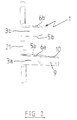
- Figure 1 shows a hinge for a vehicle door automobile consisting of a first knuckle 1 connected to the door of a vehicle and a second knuckle 2 fixed to a structural element of the vehicle and connected to the first knuckle 1 by a hinge pin, not shown in the figure.
- the first knuckle is composed of a foot 21 comprising two fixing holes allowing its attachment to the vehicle door and two elements of holding 3a and 3b extending from a lateral edge of the foot 21, in a direction substantially perpendicular to the latter.
- Each holding element 3a and 3b of the first knuckle 1 comprises respectively a bore 6a and 6b arranged in the same axis of so as to receive the hinge pin, not shown in the figures, joining the first knuckle 1 to the second knuckle 2.
- These bores 6a and 6b of the first knuckle 1 open respectively on two bearing faces 5a and 5b facing each other, intended to come respectively opposite bearing faces second knuckle 2.
- the second knuckle 2 is composed of a foot 22 which is fixed by welding to the structural element of the vehicle and a holding element 4 extending from a lateral edge of the foot 22 in a direction substantially perpendicular to the latter.
- the holding element 4 of the second knuckle 2 comprises, at near its end, a bore 7 intended to receive the hinge pin connecting the second knuckle 2 to the first knuckle 1.
- This bore 7 opens on either side of the element of holding 4 on two support faces 8a and 8b circular intended to come respectively facing the bearing faces 5a and 5b of the first knuckle 1.
- the holding element 4 of the second knuckle also comprises at its end two guide faces 14a and 14b respectively juxtaposed with the bearing faces 8a and 8b carried by the end of the element holding 4. These guide faces 14a and 14b are slightly inclined one relative to each other so that the end of the holding element 4 either converge.
- the holding element 3a of the first knuckle 1 has a part 9 extending beyond bore 6a.
- This part 9 includes, in the extension of the bearing face 5a, a bearing wall 10 whose dimensions are adapted to cooperate with the bearing face 8a of the second knuckle 2.
- This support wall 10 is inclined by about 1 ° relative to the support face 5a so that the angle formed by these two faces is projecting.
- the holding element 4 of the second knuckle 2 shown in FIG. 3, has a wall 11 projecting a few millimeters bordering partially the bearing face 8b and along an edge of the guide face 14b.
- This wall 11, of circular shape around the bearing face 8b is disposed only on the part of the support face 8b and of the face of guide 14b oriented towards the front and towards the interior of the vehicle in order to allow the approach, from the other side, of the bearing face 5b of the first knuckle 1.
- the two holding elements 3a and 3b of the first knuckle 1 come from either side of the holding element 4 of the second knuckle 2 in order to block in translation the knuckles in the direction of the axis of articulation, the blocking in translation along the plane perpendicular to the articulation axis being produced by the axis itself.
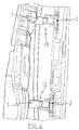
- This figure shows a door fitted with a first hinge 12, identical to that described in FIGS. 1 to 3, arranged in the part bottom of the door and a second hinge 13, symmetrical to the hinge 12 with respect to the median plane perpendicular to the axis of hinges, arranged along the same axis, in the upper part of the door.
- the door is brought towards the vehicle by open position.
- the operator maneuvers the door so that, for each of the hinges 12 and 13, the bearing wall 10 of the element of holding 3a of the first knuckle 1 comes opposite the bearing face 8a carried by the holding element 4 of the second knuckle 2.
- This positioning of the door is facilitated by the inclination of about 1 ° from the normal of the walls support 10 with respect to the articulation axis making it possible to increase the interval between the support walls 10 as well as by the converging end of the holding element 4 of the second knuckles 2 at the faces of guides 14a and 14b.
- the support wall 10 of the first knuckle 1 of the hinge 13 is then brought against the bearing face 8a of the second knuckle 2, a slight clearance then appearing between the support wall 10 and the support face 8a of the hinge 12.
- the door is then pushed by the operator, perpendicular to the axis of the hinges, so that for each hinge 12 and 13, the bearing face 5b of the second knuckle 2 is engaged on the guide face 14b of the first knuckle 1 and that simultaneously the end of the element of holding 3b of the first knuckle 1 comes into contact with the wall 11 of the second knuckle 2.
- the bores 6a, 6b and 7 then being substantially coaxial, the positioning of the axes is simplified, the latter having chamfered edges allowing to make up for slight shifts.
- the establishment of the axis allows then to refocus the bores 6a, 6b and 7, the dimensions of the first and second knuckle 1 and 2 being adapted to leave a slight play between the end of the holding element 3b of the first knuckle 1 and the wall 11 of the second knuckle 2 to allow their free rotation.
- the hinge thus produced allows rapid mounting of doors on a vehicle and this without risk of exceeding the mounting position of the hinge pin, the hinge incorporating guide faces limiting everything overshoot.
- This hinge is particularly interesting for mounting of doors having, in the open position, a very small clearance between an element of the vehicle and the outer edge of the door, such as doors with curved lines at the hinges or with very little play between the door and bodywork. Indeed, by limiting the risks of impact between the sheet door and the vehicle, the hinge according to the invention makes it possible to reduce considerably the number of alterations to be made on the doors, which largely compensates for the additional cost of this hinge compared to a traditional hinge.
- the hinges mounted on the doors can be identical, whether mounted in the upper or lower part of the door.
- the means for guiding the door during its docking on the vehicle can be carried by only one of the hinges fitted to the door.
- the means for guiding the door during its docking on the vehicle can be carried by hinge appendages not belonging to the elements for holding the hinge pin.
Landscapes
- Engineering & Computer Science (AREA)
- Mechanical Engineering (AREA)
- Hinges (AREA)
Abstract
Description
La présente invention se rapporte à une charnière et vise plus particulièrement une charnière pour porte de véhicule automobile comportant un premier charnon fixé à un ouvrant et relié, par un axe d'articulation rapporté, à un second charnon fixé à la structure du véhicule.The present invention relates to a hinge and aims more particularly a hinge for a motor vehicle door comprising a first knuckle fixed to an opening and connected, by a hinge pin reported, to a second knuckle attached to the structure of the vehicle.
Classiquement, les premier et second charnons des charnières munies d'un axe d'articulation rapporté comportent au moins un prolongement pourvu d'un alésage destiné à recevoir l'axe d'articulation de façon à former un élément de maintien de l'axe d'articulation. Cet alésage porté par les charnons est généralement entouré d'une face d'appui circulaire, perpendiculaire à l'axe de l'alésage, destinée à venir en appui contre la face d'appui de l'élément de maintien du charnon venant en vis à vis, empêchant ainsi tout mouvement relatif des premier et second charnon suivant la direction de l'axe d'articulation.Conventionally, the first and second hinges of the hinges fitted with an attached hinge pin have at least one extension provided with a bore intended to receive the articulation axis of so as to form a holding element for the hinge pin. This bore carried by the knuckles is generally surrounded by a circular bearing face, perpendicular to the axis of the bore, intended to bear against the face support of the hinge holding element coming opposite, preventing thus any relative movement of the first and second knuckles following the direction of the articulation axis.
De telles charnières présentent l'inconvénient de rendre délicat l'assemblage de la porte sur le véhicule, la mise en place des axes d'articulation rapportés, qui s'effectue alors que la porte est en position ouverte pour avoir accès aux charnières, nécessitant préalablement la mise en contact des faces d'appui et l'alignement des alésages portés par les éléments de maintien des différents charnons. Cet alignement est d'autant plus difficile à effectuer que le poids de la porte est important et il n'est pas rare, lors de l'opération de montage de cette dernière, que la partie avant de la porte vienne heurter le véhicule, endommageant ainsi le bord ou la peau extérieure de cette dernière. Ces dommages crées par le contact ponctuel du bord de la porte sur un élément du véhicule entraíne des retouches coûteuses des pièces pour lesquelles l'aspect extérieur, reflétant la qualité du produit, doit être parfait. Such hinges have the drawback of making them delicate assembling the door on the vehicle, setting up the axes hinge, which takes place while the door is in position open to have access to the hinges, requiring prior installation contact of the bearing faces and the alignment of the bores carried by the elements holding the different knuckles. This alignment is all the more difficult to carry out that the weight of the door is important and it is not rare, during the assembly operation of the latter, that the front part of the door strike the vehicle, damaging the edge or the outer skin of the latter. This damage created by the point contact of the edge of the relates to an element of the vehicle entails costly touch-up of the parts for which the external appearance, reflecting the quality of the product, must be perfect.
Il est connu, pour réduire les risques de dommages au montage, de dessiner des portes possédant des lignes à faible courbure du côté des charnières et de laisser un espace adapté entre le bord de la portière et les éléments du véhicule afin de permettre un débattement suffisant de la porte autour de la position d'engagement des axes d'articulation sans que ceci ne génère de chocs entre la portière et le véhicule.It is known to reduce the risk of damage to the assembly, to draw doors with lines with small curvature on the side of hinges and leave a suitable space between the edge of the door and the vehicle components to allow sufficient door travel around the engagement position of the hinge pins without this generates shocks between the door and the vehicle.
Toutefois, l'aspect extérieur des véhicules étant de plus en plus important, il devient nécessaire de réduire l'espace entre la porte et la carrosserie, lorsque celle ci est en position fermée, et de pouvoir développer des portières au dessin galbé, possédant des lignes aux courbures prononcées du côté des charnières.However, the exterior appearance of vehicles is increasingly important, it becomes necessary to reduce the space between the door and the bodywork, when it is in the closed position, and to be able to develop curved doors, with pronounced curvature lines on the side of the hinges.
Le montage de ces portes, dont l'espace libre entre le bord de la porte et le véhicule est réduit lorsque la porte est en position ouverte, nécessite un soin particulier, non compatible avec le montage à la chaíne, pour éviter la multiplication des dommages résultant d'un léger dépassement de la position d'engagement des axes d'articulation.The mounting of these doors, including the free space between the edge of the door and the vehicle is reduced when the door is in the open position, requires special care, not compatible with chain assembly, to avoid the multiplication of damage resulting from a slight overshoot the engagement position of the hinge pins.
Le but de la présente invention est donc de proposer une charnière, ainsi qu'une porte équipée de cette charnière, facilitant le montage de l'axe d'articulation rapporté en supprimant les risques de dépassement prononcé de la position d'engagement de ce dernier et qui soit simple et économique à réaliser.The object of the present invention is therefore to propose a hinge, as well as a door fitted with this hinge, facilitating assembly of the hinge pin added by eliminating the risk of overshoot pronounced from the engagement position of the latter and which is simple and economical to achieve.
L'invention a pour objet une charnière, en particulier pour véhicule automobile, comportant un premier charnon, fixé à un ouvrant, et un second charnon, fixé à la structure du véhicule, solidarisés entre eux par un axe d'articulation rapporté, le premier charnon étant pourvu d'au moins un élément de maintien possédant un alésage destiné à recevoir une partie de l'axe d'articulation, l'autre partie s'engageant dans un alésage appartenant à un élément de maintien porté par le second charnon.The subject of the invention is a hinge, in particular for motor vehicle, comprising a first knuckle, fixed to an opening leaf, and a second knuckle, fixed to the structure of the vehicle, joined together by an added hinge pin, the first knuckle being provided with at least one holding element having a bore intended to receive a part of the axis of articulation, the other part engaging in a bore belonging to a holding element carried by the second knuckle.
Selon l'invention la charnière est caractérisée en ce que les premier et second charnons coopèrent avec des moyens de guidage destinés à limiter les déplacements relatifs de la porte par rapport à la structure du véhicule et à faciliter l'alignement des alésages pour la mise en place de l'axe d'articulation.According to the invention the hinge is characterized in that the first and second knuckles cooperate with guide means intended to limit the relative movements of the door relative to the structure of the vehicle and to facilitate the alignment of the bores for the positioning of the axis of articulation.
Selon une autre caractéristique de la charnière selon l'invention, les moyens de guidage limitent les déplacements relatifs de la porte par rapport à la structure du véhicule selon la direction de l'axe d'articulation.According to another characteristic of the hinge according to the invention, the guide means limit the relative movements of the door by relation to the structure of the vehicle in the direction of the hinge axis.
Selon une autre caractéristique de la charnière selon l'invention, les moyens de guidages se composent d'une paroi d'appui portée par l'élément de maintien du premier charnon et d'une surface portée par l'élément de maintien du second charnon, la paroi d'appui étant disposée sur une partie de l'élément de maintien se prolongeant au delà de l'alésage de ce dernier.According to another characteristic of the hinge according to the invention, the guide means consist of a support wall carried by the holding element of the first knuckle and of a surface carried by the holding element of the second knuckle, the bearing wall being arranged on part of the retaining element extending beyond the bore of this latest.
Selon une autre caractéristique de la charnière selon l'invention, les dimensions de la paroi d'appui du premier charnon sont adaptées à la surface de contact du second charnon.According to another characteristic of the hinge according to the invention, the dimensions of the support wall of the first knuckle are adapted to the contact surface of the second knuckle.
Selon une autre caractéristique de la charnière selon l'invention, la normale à la paroi d'appui du premier charnon est légèrement inclinée par rapport à l'axe de l'alésage.According to another characteristic of the hinge according to the invention, the normal to the bearing wall of the first knuckle is slightly inclined by relative to the axis of the bore.
Selon encore une autre caractéristique de la charnière selon l'invention, les moyens de guidage limitent les déplacements relatifs de la porte par rapport à la structure du véhicule selon un plan perpendiculaire à l'axe d'articulation.According to yet another characteristic of the hinge according to the invention, the guide means limit the relative displacements of the door relative to the structure of the vehicle along a plane perpendicular to the axis of articulation.
Selon une autre caractéristique de la charnière selon l'invention, les moyens de guidage se composent d'une paroi en saillie portée par l'élément de maintien du second charnon et de l'extrémité de l'élément de maintien du premier charnon, la paroi en saillie étant de forme adaptée de façon à entourer partiellement l'extrémité de l'élément de maintien du premier charnon. According to another characteristic of the hinge according to the invention, the guide means consist of a projecting wall carried by the holding element of the second knuckle and the end of the element of maintenance of the first knuckle, the projecting wall being of a shape adapted to so as to partially surround the end of the holding element of the first knuckle.
Selon une autre caractéristique de la charnière selon l'invention, le premier charnon comporte un premier et un second élément de maintien encadrant l'élément de maintien du second charnon, le premier élément de maintien du premier charnon comportant des moyens de guidage limitant les déplacements suivant la direction de l'axe d'articulation en coopérant avec l'élément de maintien du second charnon, le second élément de maintien du premier charnon comportant des moyens de guidage limitant les déplacements suivant le plan perpendiculaire à l'axe d'articulation en coopérant avec l'élément de maintien du second charnon.According to another characteristic of the hinge according to the invention, the first knuckle has first and second holding elements framing the holding element of the second knuckle, the first element of maintenance of the first knuckle comprising guide means limiting the displacements in the direction of the articulation axis by cooperating with the holding element of the second knuckle, the second holding element of the first knuckle comprising guide means limiting the displacements along the plane perpendicular to the axis of articulation in cooperating with the holding element of the second knuckle.
L'invention concerne également une porte de véhicule automobile équipée de deux charnières du type défini ci-dessus, caractérisée en ce que les deux charnières sont symétriques l'une de l'autre par rapport à un plan perpendiculaire à l'axe d'articulation des charnières.The invention also relates to a motor vehicle door equipped with two hinges of the type defined above, characterized in that the two hinges are symmetrical to each other with respect to a plane perpendicular to the hinge axis of articulation.
On comprendra mieux les buts, aspects et avantages de la présente invention, d'après la description donnée ci-après de différents modes de réalisation de l'invention, présentés à titre d'exemples non limitatifs, en se référant aux dessins annexés, dans lesquels :
- la figure 1 représente une vue en perspective d'un mode de réalisation particulier d'une charnière selon l'invention ;
- la figure 2 est une vue en perspective du premier charnon de la charnière représentée à la figure 1 ;
- la figure 3 est une vue en perspective du second charnon de la charnière représentée à la figure 1 ;
- la figure 4 est une vue partielle, en perspective, d'une porte et d'un élément de structure d'un véhicule équipé de charnières du type de celle représentée à la figure 1.
- Figure 1 shows a perspective view of a particular embodiment of a hinge according to the invention;
- Figure 2 is a perspective view of the first knuckle of the hinge shown in Figure 1;
- Figure 3 is a perspective view of the second knuckle of the hinge shown in Figure 1;
- FIG. 4 is a partial perspective view of a door and of a structural element of a vehicle fitted with hinges of the type shown in FIG. 1.
Pour faciliter la lecture des dessins, les mêmes pièces portent les mêmes références d'une figure à l'autre. Par ailleurs, seuls les éléments nécessaires à la compréhension de l'invention ont été figurés.To facilitate the reading of the drawings, the same parts bear the same references from one figure to another. Furthermore, only the elements necessary for understanding the invention have been shown.
La figure 1 présente une charnière pour porte de véhicule
automobile se composant d'un premier charnon 1 relié à la porte d'un
véhicule et d'un second charnon 2 fixé à un élément de structure du véhicule
et relié au premier charnon 1 par un axe d'articulation, non représenté sur la
figure.Figure 1 shows a hinge for a vehicle door
automobile consisting of a
Comme on peut le voir plus précisément sur les figures 1 et 2, le
premier charnon est composé d'un pied 21 comportant deux trous de fixation
permettant sa fixation sur la porte du véhicule et de deux éléments de
maintien 3a et 3b s'étendant depuis un bord latéral du pied 21, dans une
direction sensiblement perpendiculairement à ce dernier.As can be seen more precisely in Figures 1 and 2, the
first knuckle is composed of a
Chaque élément de maintien 3a et 3b du premier charnon 1
comporte respectivement un alésage 6a et 6b disposé dans un même axe de
façon à recevoir l'axe d'articulation, non représenté sur les figures,
solidarisant le premier charnon 1 au second charnon 2. Ces alésages 6a et 6b
du premier charnon 1 débouchent respectivement sur deux faces d'appui 5a
et 5b en vis à vis, destinées à venir respectivement en regard de faces d'appui
du second charnon 2.Each
En se reportant aux figures 1 et 3, on voit que le second charnon
2 est composé d'un pied 22 se fixant par soudage à l'élément de structure du
véhicule et d'un élément de maintien 4 s'étendant depuis un bord latéral du
pied 22 dans une direction sensiblement perpendiculairement à ce dernier.Referring to Figures 1 and 3, we see that the
L'élément de maintien 4 du second charnon 2 comporte, à
proximité de son extrémité, un alésage 7 destiné à recevoir l'axe d'articulation
reliant le second charnon 2 au premier charnon 1. The
Cet alésage 7 débouche de part et d'autre de l'élément de
maintien 4 sur deux faces d'appui 8a et 8b circulaires destinées à venir
respectivement en regard des faces d'appui 5a et 5b du premier charnon 1.This
L'élément de maintien 4 du second charnon comporte également
à son extrémité deux faces de guidages 14a et 14b respectivement
juxtaposées aux faces d'appui 8a et 8b portées par l'extrémité de l'élément de
maintien 4. Ces faces de guidage 14a et 14b sont légèrement inclinées l'une
par rapport à l'autre de façon à ce que l'extrémité de l'élément de maintien 4
soit convergente.The
Pour faciliter l'accostage du premier charnon 1 sur le second
charnon 2 suivant la direction de l'axe d'articulation, l'élément de maintien 3a
du premier charnon 1, représenté sur la figure 2, comporte une partie 9 se
prolongeant au delà de l'alésage 6a. Cette partie 9 comprend, dans le
prolongement de la face d'appui 5a, une paroi d'appui 10 dont les dimensions
sont adaptées pour coopérer avec la face d'appui 8a du second charnon 2.
Cette paroi d'appui 10 est inclinée d'environ 1° par rapport à la face d'appui
5a de façon à ce que l'angle formé par ces deux faces soit saillant.To facilitate docking of the
De même, afin de faciliter l'accostage du premier charnon 1 sur le
second charnon 2 suivant le plan perpendiculaire à l'axe d'articulation,
l'élément de maintien 4 du second charnon 2, représenté sur la figure 3,
comporte une paroi 11 en saillie de quelques millimètres bordant
partiellement la face d'appui 8b et longeant un bord de la face de guidage
14b. Cet paroi 11, de forme circulaire autour de la face d'appui 8b, est
disposée uniquement sur la partie de la face d'appui 8b et de la face de
guidage 14b orientée vers l'avant et vers l'intérieur du véhicule afin de
permettre l'approche, par l'autre coté, de la face d'appui 5b du premier
charnon 1.Similarly, in order to facilitate docking of the
Une fois la charnière assemblée, ainsi qu'elle est représentée sur
la figure 1, les deux éléments de maintien 3a et 3b du premier charnon 1
viennent de part et d'autre de l'élément de maintien 4 du second charnon 2
afin d'effectuer le blocage en translation des charnons suivant la direction de
l'axe d'articulation, le blocage en translation suivant le plan perpendiculaire à
l'axe d'articulation étant réalisé par l'axe lui-même.Once the hinge is assembled, as shown in
Figure 1, the two
La phase de montage sur un véhicule d'une porte, équipée de telles charnières, est représentée sur la figure 4.The assembly phase on a vehicle of a door, equipped with such hinges, is shown in Figure 4.
Cette figure présente une porte équipée d'une première charnière
12, identique à celle décrite sur les figures 1 à 3, disposée dans la partie
inférieure de la porte et d'une seconde charnière 13, symétrique de la
charnière 12 par rapport au plan médian perpendiculaire à l'axe des
charnières, disposée suivant le même axe, dans la partie supérieure de la
porte.This figure shows a door fitted with a
Lors de la phase de montage de la porte sur le véhicule, comme
on peut le voir sur la figure 4, la porte est amenée en direction du véhicule en
position ouverte. L'opérateur manoeuvre alors la porte de façon à ce que,
pour chacune des charnières 12 et 13, la paroi d'appui 10 de l'élément de
maintien 3a du premier charnon 1 vienne en regard de la face d'appui 8a
portée par l'élément de maintien 4 du second charnon 2. Cette mise en place
de la porte est facilitée par l'inclinaison d'environ 1° de la normale des parois
d'appui 10 par rapport à l'axe d'articulation permettant d'augmenter
l'intervalle entre les parois d'appui 10 ainsi que par l'extrémité convergente de
l'élément de maintien 4 des second charnons 2 au niveau des faces de
guidages 14a et 14b.During the assembly phase of the door on the vehicle, as
we can see it in figure 4, the door is brought towards the vehicle by
open position. The operator then maneuvers the door so that,
for each of the
La paroi d'appui 10 du premier charnon 1 de la charnière 13 est
ensuite amenée contre la face d'appui 8a du second charnon 2, un léger jeu
apparaissant alors entre la paroi d'appui 10 et la face d'appui 8a de la
charnière 12.The
La porte est alors poussée par l'opérateur, perpendiculairement à
l'axe des charnières, de façon à ce que pour chaque charnière 12 et 13, la
face d'appui 5b du second charnon 2 soit engagée sur la face de guidage 14b
du premier charnon 1 et que simultanément l'extrémité de l'élément de
maintien 3b du premier charnon 1 vienne en contact avec la paroi 11 du
second charnon 2.The door is then pushed by the operator, perpendicular to
the axis of the hinges, so that for each
Le guidage de l'élément de maintien 3b du premier charnon 1 sur
la paroi 11 du second charnon 2 associé à la poussée de l'opérateur sur la
porte amène enfin cette dernière en position finale où l'extrémité circulaire de
l'élément de maintien 3b du premier charnon 1 est en appui contre la portion
en arc de cercle de la paroi 11 du second charnon 2.The guidance of the
Les alésages 6a, 6b et 7 étant alors sensiblement coaxiaux, la
mise en place des axes est simplifiée, ces derniers ayant des bords chanfreinés
permettant de rattraper les légers décalages. La mise en place de l'axe permet
alors de recentrer les alésages 6a, 6b et 7, les dimensions des premier et
second charnon 1 et 2 étant adaptées afin de laisser un léger jeu entre
l'extrémité de l'élément de maintien 3b du premier charnon 1 et la paroi 11 du
second charnon 2 pour permettre leur libre rotation.The
La charnière ainsi réalisée permet le montage rapide de portes sur un véhicule et ceci sans risque de dépassement de la position de montage de l'axe d'articulation, la charnière intégrant des faces de guidage limitant tout dépassement.The hinge thus produced allows rapid mounting of doors on a vehicle and this without risk of exceeding the mounting position of the hinge pin, the hinge incorporating guide faces limiting everything overshoot.
Cette charnière est particulièrement intéressante pour le montage de portes possédant, en position ouverte, un très faible jeu entre un élément du véhicule et le bord extérieur de la porte, comme par exemple des portes aux lignes courbes au niveau des charnières ou avec un très faible jeu entre la porte et la carrosserie. En effet, en limitant les risques de choc entre la tôle de porte et le véhicule, la charnière selon l'invention permet de réduire considérablement le nombre de retouches à effectuer sur les portes, ce qui permet de compenser largement le surcoût de cette charnière par rapport à une charnière traditionnelle.This hinge is particularly interesting for mounting of doors having, in the open position, a very small clearance between an element of the vehicle and the outer edge of the door, such as doors with curved lines at the hinges or with very little play between the door and bodywork. Indeed, by limiting the risks of impact between the sheet door and the vehicle, the hinge according to the invention makes it possible to reduce considerably the number of alterations to be made on the doors, which largely compensates for the additional cost of this hinge compared to a traditional hinge.
Bien entendu, l'invention n'est nullement limitée aux modes de réalisation décrits et illustrés qui n'ont été donnés qu'à titre d'exemple. Of course, the invention is in no way limited to the modes of realization described and illustrated which have been given only by way of example.
Au contraire, l'invention comprend tous les équivalents techniques des moyens décrits ainsi que leurs combinaisons si celles-ci sont effectuées suivant son esprit.On the contrary, the invention includes all equivalents techniques of the means described as well as their combinations if these are carried out according to his spirit.
Ainsi, les charnières montées sur les portes peuvent être identiques, quelles soient montées dans la partie supérieure ou inférieure de la porte.Thus, the hinges mounted on the doors can be identical, whether mounted in the upper or lower part of the door.
Ainsi, les moyens de guidage de la porte lors de son accostage sur le véhicule peuvent être portés par une seule des charnières équipant la porte.Thus, the means for guiding the door during its docking on the vehicle can be carried by only one of the hinges fitted to the door.
Ainsi, les moyens de guidage de la porte lors de son accostage sur le véhicule peuvent être portés par des appendices des charnières n'appartenant pas aux éléments de maintien de l'axe d'articulation.Thus, the means for guiding the door during its docking on the vehicle can be carried by hinge appendages not belonging to the elements for holding the hinge pin.
Claims (6)
Applications Claiming Priority (2)
| Application Number | Priority Date | Filing Date | Title |
|---|---|---|---|
| FR9610887A FR2753226B1 (en) | 1996-09-06 | 1996-09-06 | DOOR HINGE, ESPECIALLY FOR A MOTOR VEHICLE |
| FR9610887 | 1996-09-06 |
Publications (2)
| Publication Number | Publication Date |
|---|---|
| EP0828050A1 true EP0828050A1 (en) | 1998-03-11 |
| EP0828050B1 EP0828050B1 (en) | 2003-01-29 |
Family
ID=9495512
Family Applications (1)
| Application Number | Title | Priority Date | Filing Date |
|---|---|---|---|
| EP97402069A Expired - Lifetime EP0828050B1 (en) | 1996-09-06 | 1997-09-05 | Door hinge, in particular for vehicles |
Country Status (3)
| Country | Link |
|---|---|
| EP (1) | EP0828050B1 (en) |
| DE (1) | DE69718728T2 (en) |
| FR (1) | FR2753226B1 (en) |
Cited By (2)
| Publication number | Priority date | Publication date | Assignee | Title |
|---|---|---|---|---|
| WO2006125535A1 (en) * | 2005-05-21 | 2006-11-30 | Bayerische Motoren Werke Aktiengesellschaft | Hinge pin and hinge |
| DE102015216159B3 (en) * | 2015-08-25 | 2016-03-10 | Bayerische Motoren Werke Aktiengesellschaft | Fastening device for movable, in particular rotatable, storing a vehicle door on a vehicle body |
Citations (3)
| Publication number | Priority date | Publication date | Assignee | Title |
|---|---|---|---|---|
| DE284455C (en) * | ||||
| EP0149492A2 (en) * | 1984-01-16 | 1985-07-24 | Lunke & Sohn Aktiengesellschaft | Door hinge for motor vehicles |
| DE3606813C1 (en) * | 1986-03-03 | 1987-07-02 | Daimler Benz Ag | Repeatedly mountable door hinge, especially for motor-vehicle doors |
Family Cites Families (1)
| Publication number | Priority date | Publication date | Assignee | Title |
|---|---|---|---|---|
| DE3940926C2 (en) * | 1989-10-17 | 1997-09-04 | Scharwaechter Gmbh Co Kg | Removable door hinge for motor vehicle doors |
-
1996
- 1996-09-06 FR FR9610887A patent/FR2753226B1/en not_active Expired - Fee Related
-
1997
- 1997-09-05 DE DE69718728T patent/DE69718728T2/en not_active Expired - Lifetime
- 1997-09-05 EP EP97402069A patent/EP0828050B1/en not_active Expired - Lifetime
Patent Citations (3)
| Publication number | Priority date | Publication date | Assignee | Title |
|---|---|---|---|---|
| DE284455C (en) * | ||||
| EP0149492A2 (en) * | 1984-01-16 | 1985-07-24 | Lunke & Sohn Aktiengesellschaft | Door hinge for motor vehicles |
| DE3606813C1 (en) * | 1986-03-03 | 1987-07-02 | Daimler Benz Ag | Repeatedly mountable door hinge, especially for motor-vehicle doors |
Cited By (2)
| Publication number | Priority date | Publication date | Assignee | Title |
|---|---|---|---|---|
| WO2006125535A1 (en) * | 2005-05-21 | 2006-11-30 | Bayerische Motoren Werke Aktiengesellschaft | Hinge pin and hinge |
| DE102015216159B3 (en) * | 2015-08-25 | 2016-03-10 | Bayerische Motoren Werke Aktiengesellschaft | Fastening device for movable, in particular rotatable, storing a vehicle door on a vehicle body |
Also Published As
| Publication number | Publication date |
|---|---|
| FR2753226A1 (en) | 1998-03-13 |
| DE69718728D1 (en) | 2003-03-06 |
| EP0828050B1 (en) | 2003-01-29 |
| FR2753226B1 (en) | 1998-11-27 |
| DE69718728T2 (en) | 2003-11-20 |
Similar Documents
| Publication | Publication Date | Title |
|---|---|---|
| EP1574638B1 (en) | Arrangement of a handle support, blocking means and external handle element and method for fixing the external handle element to the handle support. | |
| EP1026349B1 (en) | Handle for a motor vehicle wing | |
| EP2200851B1 (en) | Motor vehicle front end module | |
| EP2125498B1 (en) | Device for positioning a piece of car body work on a motor vehicle | |
| EP0493225A1 (en) | Pivoting side door for motor vehicle | |
| EP1048521B1 (en) | Optical block mounting device on vehicle body parts | |
| FR2782040A1 (en) | Retractable stowage ring, used on vehicles, has cut-out in upper face of edge of vehicle, with stowage ring retractable into space formed by cut-out and beneath ring support, which is fitted into cut-out. | |
| EP0828050B1 (en) | Door hinge, in particular for vehicles | |
| EP1215949A1 (en) | Housing for an electronic apparatus | |
| FR2816272A1 (en) | FRONT PANEL WITH SHIELD FOR MOTOR VEHICLE | |
| FR3063301B1 (en) | ARTICULATING HINGE OF AN OPENING OF THE TYPE CLOSING COVER OF THE ENGINE COMPARTMENT ON A BODY OF A MOTOR VEHICLE | |
| EP0742329B1 (en) | Vehicle locking device comprising improved mounting means for trim cap | |
| FR2925430A1 (en) | IMPROVED BUMPER SKIN | |
| FR3134351A1 (en) | Vehicle body side comprising a means of retaining a sliding door in the event of a transverse impact from the passenger compartment to the outside. | |
| FR3041307A1 (en) | WIPER ORGAN COMPRISING AN ARTICULATED HOOD | |
| EP3044020B1 (en) | Motor vehicle tailgate comprising a support frame and corresponding vehicle | |
| EP3670271B1 (en) | Deployment device of a camera for a motor-propelled vehicle | |
| FR3123020A1 (en) | MOTOR VEHICLE SIDE DOOR FOR VEHICLE WITH COVERING OR NON-COVERING DOOR | |
| EP4185490A1 (en) | Storage with mobile interior shutter | |
| FR3125788A1 (en) | Motor vehicle with at least one moving guide part of the bonnet in the event of a frontal impact. | |
| WO2014184500A2 (en) | Tailgate intended to be pivotably mounted onto motor vehicle bodywork, having improved abutment | |
| EP1283316A1 (en) | Improved key with articulated bit | |
| EP4279342A1 (en) | Device for connecting a wiper blade | |
| EP0767079A1 (en) | Beam for a trailer | |
| FR3102454A1 (en) | TRIM SUPPORT FOR A MOTOR VEHICLE DOOR, ESPECIALLY OF THE TAILGATE TYPE |
Legal Events
| Date | Code | Title | Description |
|---|---|---|---|
| PUAI | Public reference made under article 153(3) epc to a published international application that has entered the european phase |
Free format text: ORIGINAL CODE: 0009012 |
|
| AK | Designated contracting states |
Kind code of ref document: A1 Designated state(s): BE DE ES GB IT |
|
| AX | Request for extension of the european patent |
Free format text: AL;LT;LV;RO;SI |
|
| 17P | Request for examination filed |
Effective date: 19980811 |
|
| AKX | Designation fees paid |
Free format text: BE DE ES GB IT |
|
| RBV | Designated contracting states (corrected) |
Designated state(s): BE DE ES GB IT |
|
| 17Q | First examination report despatched |
Effective date: 20010330 |
|
| GRAG | Despatch of communication of intention to grant |
Free format text: ORIGINAL CODE: EPIDOS AGRA |
|
| GRAG | Despatch of communication of intention to grant |
Free format text: ORIGINAL CODE: EPIDOS AGRA |
|
| GRAH | Despatch of communication of intention to grant a patent |
Free format text: ORIGINAL CODE: EPIDOS IGRA |
|
| RAP1 | Party data changed (applicant data changed or rights of an application transferred) |
Owner name: RENAULT S.A.S. |
|
| GRAH | Despatch of communication of intention to grant a patent |
Free format text: ORIGINAL CODE: EPIDOS IGRA |
|
| GRAA | (expected) grant |
Free format text: ORIGINAL CODE: 0009210 |
|
| AK | Designated contracting states |
Designated state(s): BE DE ES GB IT |
|
| PG25 | Lapsed in a contracting state [announced via postgrant information from national office to epo] |
Ref country code: GB Free format text: LAPSE BECAUSE OF FAILURE TO SUBMIT A TRANSLATION OF THE DESCRIPTION OR TO PAY THE FEE WITHIN THE PRESCRIBED TIME-LIMIT Effective date: 20030129 |
|
| REG | Reference to a national code |
Ref country code: GB Ref legal event code: FG4D Free format text: NOT ENGLISH |
|
| REF | Corresponds to: |
Ref document number: 69718728 Country of ref document: DE Date of ref document: 20030306 Kind code of ref document: P |
|
| GBV | Gb: ep patent (uk) treated as always having been void in accordance with gb section 77(7)/1977 [no translation filed] |
Effective date: 20030129 |
|
| PG25 | Lapsed in a contracting state [announced via postgrant information from national office to epo] |
Ref country code: ES Free format text: LAPSE BECAUSE OF FAILURE TO SUBMIT A TRANSLATION OF THE DESCRIPTION OR TO PAY THE FEE WITHIN THE PRESCRIBED TIME-LIMIT Effective date: 20030730 |
|
| PLBE | No opposition filed within time limit |
Free format text: ORIGINAL CODE: 0009261 |
|
| STAA | Information on the status of an ep patent application or granted ep patent |
Free format text: STATUS: NO OPPOSITION FILED WITHIN TIME LIMIT |
|
| 26N | No opposition filed |
Effective date: 20031030 |
|
| PGFP | Annual fee paid to national office [announced via postgrant information from national office to epo] |
Ref country code: BE Payment date: 20120920 Year of fee payment: 16 |
|
| BERE | Be: lapsed |
Owner name: *RENAULT S.A.S. Effective date: 20130930 |
|
| PG25 | Lapsed in a contracting state [announced via postgrant information from national office to epo] |
Ref country code: BE Free format text: LAPSE BECAUSE OF NON-PAYMENT OF DUE FEES Effective date: 20130930 |
|
| PGFP | Annual fee paid to national office [announced via postgrant information from national office to epo] |
Ref country code: DE Payment date: 20140922 Year of fee payment: 18 |
|
| PGFP | Annual fee paid to national office [announced via postgrant information from national office to epo] |
Ref country code: IT Payment date: 20140929 Year of fee payment: 18 |
|
| REG | Reference to a national code |
Ref country code: DE Ref legal event code: R119 Ref document number: 69718728 Country of ref document: DE |
|
| PG25 | Lapsed in a contracting state [announced via postgrant information from national office to epo] |
Ref country code: IT Free format text: LAPSE BECAUSE OF NON-PAYMENT OF DUE FEES Effective date: 20150905 |
|
| PG25 | Lapsed in a contracting state [announced via postgrant information from national office to epo] |
Ref country code: DE Free format text: LAPSE BECAUSE OF NON-PAYMENT OF DUE FEES Effective date: 20160401 |