EP0828050A1 - Charnière de porte, notamment pour véhicule automobile - Google Patents
Charnière de porte, notamment pour véhicule automobile Download PDFInfo
- Publication number
- EP0828050A1 EP0828050A1 EP97402069A EP97402069A EP0828050A1 EP 0828050 A1 EP0828050 A1 EP 0828050A1 EP 97402069 A EP97402069 A EP 97402069A EP 97402069 A EP97402069 A EP 97402069A EP 0828050 A1 EP0828050 A1 EP 0828050A1
- Authority
- EP
- European Patent Office
- Prior art keywords
- knuckle
- hinge
- door
- axis
- vehicle
- Prior art date
- Legal status (The legal status is an assumption and is not a legal conclusion. Google has not performed a legal analysis and makes no representation as to the accuracy of the status listed.)
- Granted
Links
Images


Classifications
-
- E—FIXED CONSTRUCTIONS
- E05—LOCKS; KEYS; WINDOW OR DOOR FITTINGS; SAFES
- E05D—HINGES OR SUSPENSION DEVICES FOR DOORS, WINDOWS OR WINGS
- E05D7/00—Hinges or pivots of special construction
- E05D7/10—Hinges or pivots of special construction to allow easy separation or connection of the parts at the hinge axis
- E05D7/1083—Hinges or pivots of special construction to allow easy separation or connection of the parts at the hinge axis facilitating simultaneous assembly of a plurality of hinges, e.g. for mounting heavy wings
-
- E—FIXED CONSTRUCTIONS
- E05—LOCKS; KEYS; WINDOW OR DOOR FITTINGS; SAFES
- E05D—HINGES OR SUSPENSION DEVICES FOR DOORS, WINDOWS OR WINGS
- E05D7/00—Hinges or pivots of special construction
- E05D7/10—Hinges or pivots of special construction to allow easy separation or connection of the parts at the hinge axis
- E05D7/1005—Hinges or pivots of special construction to allow easy separation or connection of the parts at the hinge axis by axially moving free pins, balls or sockets
-
- E—FIXED CONSTRUCTIONS
- E05—LOCKS; KEYS; WINDOW OR DOOR FITTINGS; SAFES
- E05D—HINGES OR SUSPENSION DEVICES FOR DOORS, WINDOWS OR WINGS
- E05D3/00—Hinges with pins
- E05D3/02—Hinges with pins with one pin
- E05D2003/025—Hinges with pins with one pin having three knuckles
- E05D2003/027—Hinges with pins with one pin having three knuckles the end knuckles being mutually connected
-
- E—FIXED CONSTRUCTIONS
- E05—LOCKS; KEYS; WINDOW OR DOOR FITTINGS; SAFES
- E05Y—INDEXING SCHEME RELATING TO HINGES OR OTHER SUSPENSION DEVICES FOR DOORS, WINDOWS OR WINGS AND DEVICES FOR MOVING WINGS INTO OPEN OR CLOSED POSITION, CHECKS FOR WINGS AND WING FITTINGS NOT OTHERWISE PROVIDED FOR, CONCERNED WITH THE FUNCTIONING OF THE WING
- E05Y2900/00—Application of doors, windows, wings or fittings thereof
- E05Y2900/50—Application of doors, windows, wings or fittings thereof for vehicles
- E05Y2900/53—Application of doors, windows, wings or fittings thereof for vehicles characterised by the type of wing
- E05Y2900/531—Doors
Definitions
- the present invention relates to a hinge and aims more particularly a hinge for a motor vehicle door comprising a first knuckle fixed to an opening and connected, by a hinge pin reported, to a second knuckle attached to the structure of the vehicle.
- the first and second hinges of the hinges fitted with an attached hinge pin have at least one extension provided with a bore intended to receive the articulation axis of so as to form a holding element for the hinge pin.
- This bore carried by the knuckles is generally surrounded by a circular bearing face, perpendicular to the axis of the bore, intended to bear against the face support of the hinge holding element coming opposite, preventing thus any relative movement of the first and second knuckles following the direction of the articulation axis.
- Such hinges have the drawback of making them delicate assembling the door on the vehicle, setting up the axes hinge, which takes place while the door is in position open to have access to the hinges, requiring prior installation contact of the bearing faces and the alignment of the bores carried by the elements holding the different knuckles.
- This alignment is all the more difficult to carry out that the weight of the door is important and it is not rare, during the assembly operation of the latter, that the front part of the door strike the vehicle, damaging the edge or the outer skin of the latter.
- This damage created by the point contact of the edge of the relates to an element of the vehicle entails costly touch-up of the parts for which the external appearance, reflecting the quality of the product, must be perfect.
- the object of the present invention is therefore to propose a hinge, as well as a door fitted with this hinge, facilitating assembly of the hinge pin added by eliminating the risk of overshoot pronounced from the engagement position of the latter and which is simple and economical to achieve.
- the subject of the invention is a hinge, in particular for motor vehicle, comprising a first knuckle, fixed to an opening leaf, and a second knuckle, fixed to the structure of the vehicle, joined together by an added hinge pin, the first knuckle being provided with at least one holding element having a bore intended to receive a part of the axis of articulation, the other part engaging in a bore belonging to a holding element carried by the second knuckle.
- the hinge is characterized in that the first and second knuckles cooperate with guide means intended to limit the relative movements of the door relative to the structure of the vehicle and to facilitate the alignment of the bores for the positioning of the axis of articulation.
- the guide means limit the relative movements of the door by relation to the structure of the vehicle in the direction of the hinge axis.
- the guide means consist of a support wall carried by the holding element of the first knuckle and of a surface carried by the holding element of the second knuckle, the bearing wall being arranged on part of the retaining element extending beyond the bore of this latest.
- the dimensions of the support wall of the first knuckle are adapted to the contact surface of the second knuckle.
- the normal to the bearing wall of the first knuckle is slightly inclined by relative to the axis of the bore.
- the guide means limit the relative displacements of the door relative to the structure of the vehicle along a plane perpendicular to the axis of articulation.
- the guide means consist of a projecting wall carried by the holding element of the second knuckle and the end of the element of maintenance of the first knuckle, the projecting wall being of a shape adapted to so as to partially surround the end of the holding element of the first knuckle.
- the first knuckle has first and second holding elements framing the holding element of the second knuckle, the first element of maintenance of the first knuckle comprising guide means limiting the displacements in the direction of the articulation axis by cooperating with the holding element of the second knuckle, the second holding element of the first knuckle comprising guide means limiting the displacements along the plane perpendicular to the axis of articulation in cooperating with the holding element of the second knuckle.
- the invention also relates to a motor vehicle door equipped with two hinges of the type defined above, characterized in that the two hinges are symmetrical to each other with respect to a plane perpendicular to the hinge axis of articulation.
- Figure 1 shows a hinge for a vehicle door automobile consisting of a first knuckle 1 connected to the door of a vehicle and a second knuckle 2 fixed to a structural element of the vehicle and connected to the first knuckle 1 by a hinge pin, not shown in the figure.
- the first knuckle is composed of a foot 21 comprising two fixing holes allowing its attachment to the vehicle door and two elements of holding 3a and 3b extending from a lateral edge of the foot 21, in a direction substantially perpendicular to the latter.
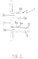
- Each holding element 3a and 3b of the first knuckle 1 comprises respectively a bore 6a and 6b arranged in the same axis of so as to receive the hinge pin, not shown in the figures, joining the first knuckle 1 to the second knuckle 2.
- These bores 6a and 6b of the first knuckle 1 open respectively on two bearing faces 5a and 5b facing each other, intended to come respectively opposite bearing faces second knuckle 2.
- the second knuckle 2 is composed of a foot 22 which is fixed by welding to the structural element of the vehicle and a holding element 4 extending from a lateral edge of the foot 22 in a direction substantially perpendicular to the latter.
- the holding element 4 of the second knuckle 2 comprises, at near its end, a bore 7 intended to receive the hinge pin connecting the second knuckle 2 to the first knuckle 1.
- This bore 7 opens on either side of the element of holding 4 on two support faces 8a and 8b circular intended to come respectively facing the bearing faces 5a and 5b of the first knuckle 1.
- the holding element 4 of the second knuckle also comprises at its end two guide faces 14a and 14b respectively juxtaposed with the bearing faces 8a and 8b carried by the end of the element holding 4. These guide faces 14a and 14b are slightly inclined one relative to each other so that the end of the holding element 4 either converge.
- the holding element 3a of the first knuckle 1 has a part 9 extending beyond bore 6a.
- This part 9 includes, in the extension of the bearing face 5a, a bearing wall 10 whose dimensions are adapted to cooperate with the bearing face 8a of the second knuckle 2.
- This support wall 10 is inclined by about 1 ° relative to the support face 5a so that the angle formed by these two faces is projecting.
- the holding element 4 of the second knuckle 2 shown in FIG. 3, has a wall 11 projecting a few millimeters bordering partially the bearing face 8b and along an edge of the guide face 14b.
- This wall 11, of circular shape around the bearing face 8b is disposed only on the part of the support face 8b and of the face of guide 14b oriented towards the front and towards the interior of the vehicle in order to allow the approach, from the other side, of the bearing face 5b of the first knuckle 1.
- the two holding elements 3a and 3b of the first knuckle 1 come from either side of the holding element 4 of the second knuckle 2 in order to block in translation the knuckles in the direction of the axis of articulation, the blocking in translation along the plane perpendicular to the articulation axis being produced by the axis itself.
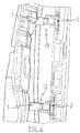
- This figure shows a door fitted with a first hinge 12, identical to that described in FIGS. 1 to 3, arranged in the part bottom of the door and a second hinge 13, symmetrical to the hinge 12 with respect to the median plane perpendicular to the axis of hinges, arranged along the same axis, in the upper part of the door.
- the door is brought towards the vehicle by open position.
- the operator maneuvers the door so that, for each of the hinges 12 and 13, the bearing wall 10 of the element of holding 3a of the first knuckle 1 comes opposite the bearing face 8a carried by the holding element 4 of the second knuckle 2.
- This positioning of the door is facilitated by the inclination of about 1 ° from the normal of the walls support 10 with respect to the articulation axis making it possible to increase the interval between the support walls 10 as well as by the converging end of the holding element 4 of the second knuckles 2 at the faces of guides 14a and 14b.
- the support wall 10 of the first knuckle 1 of the hinge 13 is then brought against the bearing face 8a of the second knuckle 2, a slight clearance then appearing between the support wall 10 and the support face 8a of the hinge 12.
- the door is then pushed by the operator, perpendicular to the axis of the hinges, so that for each hinge 12 and 13, the bearing face 5b of the second knuckle 2 is engaged on the guide face 14b of the first knuckle 1 and that simultaneously the end of the element of holding 3b of the first knuckle 1 comes into contact with the wall 11 of the second knuckle 2.
- the bores 6a, 6b and 7 then being substantially coaxial, the positioning of the axes is simplified, the latter having chamfered edges allowing to make up for slight shifts.
- the establishment of the axis allows then to refocus the bores 6a, 6b and 7, the dimensions of the first and second knuckle 1 and 2 being adapted to leave a slight play between the end of the holding element 3b of the first knuckle 1 and the wall 11 of the second knuckle 2 to allow their free rotation.
- the hinge thus produced allows rapid mounting of doors on a vehicle and this without risk of exceeding the mounting position of the hinge pin, the hinge incorporating guide faces limiting everything overshoot.
- This hinge is particularly interesting for mounting of doors having, in the open position, a very small clearance between an element of the vehicle and the outer edge of the door, such as doors with curved lines at the hinges or with very little play between the door and bodywork. Indeed, by limiting the risks of impact between the sheet door and the vehicle, the hinge according to the invention makes it possible to reduce considerably the number of alterations to be made on the doors, which largely compensates for the additional cost of this hinge compared to a traditional hinge.
- the hinges mounted on the doors can be identical, whether mounted in the upper or lower part of the door.
- the means for guiding the door during its docking on the vehicle can be carried by only one of the hinges fitted to the door.
- the means for guiding the door during its docking on the vehicle can be carried by hinge appendages not belonging to the elements for holding the hinge pin.
Abstract
Description
- la figure 1 représente une vue en perspective d'un mode de réalisation particulier d'une charnière selon l'invention ;
- la figure 2 est une vue en perspective du premier charnon de la charnière représentée à la figure 1 ;
- la figure 3 est une vue en perspective du second charnon de la charnière représentée à la figure 1 ;
- la figure 4 est une vue partielle, en perspective, d'une porte et d'un élément de structure d'un véhicule équipé de charnières du type de celle représentée à la figure 1.
Claims (6)
- Charnière, en particulier pour porte de véhicules automobiles, comportant un premier charnon (1), fixé à un ouvrant, et un second charnon (2), fixé à la structure du véhicule, solidarisés entre eux par un axe d'articulation rapporté, ledit premier charnon (1) étant pourvu d'au moins un élément de maintien (3a) possédant un alésage (6a) destiné à recevoir une partie dudit axe d'articulation, l'autre partie s'engageant dans un alésage (7) appartenant à un élément de maintien (4) porté par ledit second charnon (2), lesdits premier et second charnons (1) et (2) comportant des moyens de guidage destinés à limiter les déplacements relatifs de la porte par rapport à la structure du véhicule et à faciliter l'alignement des alésages (6a) et (7) pour la mise en place de l'axe d'articulation, caractérisé en ce que ledit élément de maintien (3a) du premier charnon (1) comporte une partie (9) se prolongeant au delà de l'alésage (6a), ladite partie (9) étant munie d'une paroi d'appui (10) coopérant avec une surface (8a) de l'élément de maintien (4) pour limiter les déplacements relatifs de la porte par rapport à la structure du véhicule selon la direction de l'axe d'articulation.
- Charnière selon la revendication 1, caractérisée en ce que les dimensions de ladite paroi d'appui (10) du premier charnon (1) sont adaptées à la surface (8a) du second charnon (2).
- Charnière selon l'une quelconque des revendications 1 à 2, caractérisée en ce que la normale à la paroi d'appui (10) dudit premier charnon (1) est légèrement inclinée par rapport à l'axe de l'alésage (6a).
- Charnière selon l'une quelconque des revendications 1 à 3, caractérisée en ce que ledit premier charnon (1) comporte un second élément de maintien (3b) muni d'un alésage (6b) destiné à recevoir une partie de l'axe d'articulation, l'extrémité dudit second élément de maintien (3b) coopérant avec une paroi (11) en saillie portée par l'élément de maintien (4) de façon à limiter les déplacements relatifs de la porte par rapport à la structure du véhicule selon un plan perpendiculaire à l'axe d'articulation, ladite paroi (11) étant de forme adaptée pour entourer partiellement l'extrémité de l'élément de maintien (3b) du premier charnon (1).
- Charnière selon la revendication 4, caractérisée en ce que lesdits premier et second élément de maintien (3a) et (3b) encadrent l'élément de maintien (4) du second charnon (2).
- Porte de véhicule automobile équipée de deux charnières (12) et (13) selon l'une quelconque des revendications 1 à 5, caractérisée en ce que lesdites charnières (12) et (13) sont symétriques l'une de l'autre par rapport à un plan perpendiculaire à l'axe d'articulation des charnières.
Applications Claiming Priority (2)
| Application Number | Priority Date | Filing Date | Title |
|---|---|---|---|
| FR9610887 | 1996-09-06 | ||
| FR9610887A FR2753226B1 (fr) | 1996-09-06 | 1996-09-06 | Charniere de porte, notamment pour vehicule automobile |
Publications (2)
| Publication Number | Publication Date |
|---|---|
| EP0828050A1 true EP0828050A1 (fr) | 1998-03-11 |
| EP0828050B1 EP0828050B1 (fr) | 2003-01-29 |
Family
ID=9495512
Family Applications (1)
| Application Number | Title | Priority Date | Filing Date |
|---|---|---|---|
| EP97402069A Expired - Lifetime EP0828050B1 (fr) | 1996-09-06 | 1997-09-05 | Charnière de porte, notamment pour véhicule automobile |
Country Status (3)
| Country | Link |
|---|---|
| EP (1) | EP0828050B1 (fr) |
| DE (1) | DE69718728T2 (fr) |
| FR (1) | FR2753226B1 (fr) |
Cited By (2)
| Publication number | Priority date | Publication date | Assignee | Title |
|---|---|---|---|---|
| WO2006125535A1 (fr) * | 2005-05-21 | 2006-11-30 | Bayerische Motoren Werke Aktiengesellschaft | Gond a charniere et charniere |
| DE102015216159B3 (de) * | 2015-08-25 | 2016-03-10 | Bayerische Motoren Werke Aktiengesellschaft | Befestigungsvorrichtung zum beweglichen, insbesondere drehbaren, Lagern einer Fahrzeugtür an einer Fahrzeugkarosserie |
Citations (3)
| Publication number | Priority date | Publication date | Assignee | Title |
|---|---|---|---|---|
| DE284455C (fr) * | ||||
| EP0149492A2 (fr) * | 1984-01-16 | 1985-07-24 | Lunke & Sohn Aktiengesellschaft | Charnière pour porte de véhicule automobile |
| DE3606813C1 (en) * | 1986-03-03 | 1987-07-02 | Daimler Benz Ag | Repeatedly mountable door hinge, especially for motor-vehicle doors |
Family Cites Families (1)
| Publication number | Priority date | Publication date | Assignee | Title |
|---|---|---|---|---|
| DE3940926C2 (de) * | 1989-10-17 | 1997-09-04 | Scharwaechter Gmbh Co Kg | Demontierbares Türscharnier für Kraftfahrzeugtüren |
-
1996
- 1996-09-06 FR FR9610887A patent/FR2753226B1/fr not_active Expired - Fee Related
-
1997
- 1997-09-05 DE DE69718728T patent/DE69718728T2/de not_active Expired - Lifetime
- 1997-09-05 EP EP97402069A patent/EP0828050B1/fr not_active Expired - Lifetime
Patent Citations (3)
| Publication number | Priority date | Publication date | Assignee | Title |
|---|---|---|---|---|
| DE284455C (fr) * | ||||
| EP0149492A2 (fr) * | 1984-01-16 | 1985-07-24 | Lunke & Sohn Aktiengesellschaft | Charnière pour porte de véhicule automobile |
| DE3606813C1 (en) * | 1986-03-03 | 1987-07-02 | Daimler Benz Ag | Repeatedly mountable door hinge, especially for motor-vehicle doors |
Cited By (2)
| Publication number | Priority date | Publication date | Assignee | Title |
|---|---|---|---|---|
| WO2006125535A1 (fr) * | 2005-05-21 | 2006-11-30 | Bayerische Motoren Werke Aktiengesellschaft | Gond a charniere et charniere |
| DE102015216159B3 (de) * | 2015-08-25 | 2016-03-10 | Bayerische Motoren Werke Aktiengesellschaft | Befestigungsvorrichtung zum beweglichen, insbesondere drehbaren, Lagern einer Fahrzeugtür an einer Fahrzeugkarosserie |
Also Published As
| Publication number | Publication date |
|---|---|
| DE69718728D1 (de) | 2003-03-06 |
| EP0828050B1 (fr) | 2003-01-29 |
| FR2753226A1 (fr) | 1998-03-13 |
| FR2753226B1 (fr) | 1998-11-27 |
| DE69718728T2 (de) | 2003-11-20 |
Similar Documents
| Publication | Publication Date | Title |
|---|---|---|
| EP1574638B1 (fr) | Ensemble de support de poignée, organe de blocage et élément externe de poignée et procédé de fixation de l'élément externe dans le support de poignée. | |
| EP1026349B1 (fr) | Poignée d'ouvrant de véhicule automobile | |
| EP2200851B1 (fr) | Face avant technique de véhicule automobile | |
| EP2125498B1 (fr) | Organe de positionnement d'une piece de carrosserie sur un vehicule automobile | |
| EP0493225A1 (fr) | Porte latérale pivotante de véhicule automobile | |
| EP1048521B1 (fr) | Dispositif de montage d'un bloc optique sur des éléments de carrosserie d'un véhicule automobile | |
| FR2782040A1 (fr) | Agencement d'anneau d'arrimage destine a etre encastre dans le bord de rive d'un vehicule tel qu'un porteur, une remorque ou semi-remorque | |
| EP0828050B1 (fr) | Charnière de porte, notamment pour véhicule automobile | |
| EP1215949A1 (fr) | Boitier d'appareil électronique | |
| FR2816272A1 (fr) | Face avant avec bouclier pour vehicule automobile | |
| FR3063301B1 (fr) | Charniere d'articulation d'un ouvrant du type capot de fermeture du compartiment moteur sur une caisse de vehicule automobile | |
| EP0742329B1 (fr) | Dispositif de verrouillage d'un ouvrant de véhicule automobile comportant des moyens perfectionnés de montage d'un capuchon d'habillage | |
| FR2925430A1 (fr) | Peau de pare-chocs amelioree | |
| FR3134351A1 (fr) | Côté de caisse de véhicule comprenant un moyen de retenue d’une porte coulissante en cas de choc transversal depuis l’habitacle vers l’extérieur. | |
| FR3041307A1 (fr) | Organe d’essuie-glace comprenant un capot articule | |
| EP3044020B1 (fr) | Hayon pour véhicule automobile avec ossature de support et véhicule correspondant | |
| EP3670271B1 (fr) | Dispositif de déploiement d'une caméra pour véhicule motorisé | |
| FR3123020A1 (fr) | Porte laterale de vehicule automobile pour vehicule a porte recouvrante ou non recouvrante | |
| EP4185490A1 (fr) | Rangement a volet interieur mobile | |
| FR3125788A1 (fr) | Véhicule automobile avec au moins une pièce de guidage en déplacement du capot en cas de choc frontal. | |
| WO2014184500A2 (fr) | Hayon destiné à être monté articulé sur une caisse de véhicule automobile, à butée perfectionnée | |
| EP1283316A1 (fr) | Clé perfectionnée à panneton articulé | |
| EP4279342A1 (fr) | Dispositif de connexion d'un balai d' essuyage | |
| EP0767079A1 (fr) | Poutre de remorquage | |
| FR3102454A1 (fr) | Support de garniture pour une porte de vehicule automobile, notamment de type hayon |
Legal Events
| Date | Code | Title | Description |
|---|---|---|---|
| PUAI | Public reference made under article 153(3) epc to a published international application that has entered the european phase |
Free format text: ORIGINAL CODE: 0009012 |
|
| AK | Designated contracting states |
Kind code of ref document: A1 Designated state(s): BE DE ES GB IT |
|
| AX | Request for extension of the european patent |
Free format text: AL;LT;LV;RO;SI |
|
| 17P | Request for examination filed |
Effective date: 19980811 |
|
| AKX | Designation fees paid |
Free format text: BE DE ES GB IT |
|
| RBV | Designated contracting states (corrected) |
Designated state(s): BE DE ES GB IT |
|
| 17Q | First examination report despatched |
Effective date: 20010330 |
|
| GRAG | Despatch of communication of intention to grant |
Free format text: ORIGINAL CODE: EPIDOS AGRA |
|
| GRAG | Despatch of communication of intention to grant |
Free format text: ORIGINAL CODE: EPIDOS AGRA |
|
| GRAH | Despatch of communication of intention to grant a patent |
Free format text: ORIGINAL CODE: EPIDOS IGRA |
|
| RAP1 | Party data changed (applicant data changed or rights of an application transferred) |
Owner name: RENAULT S.A.S. |
|
| GRAH | Despatch of communication of intention to grant a patent |
Free format text: ORIGINAL CODE: EPIDOS IGRA |
|
| GRAA | (expected) grant |
Free format text: ORIGINAL CODE: 0009210 |
|
| AK | Designated contracting states |
Designated state(s): BE DE ES GB IT |
|
| PG25 | Lapsed in a contracting state [announced via postgrant information from national office to epo] |
Ref country code: GB Free format text: LAPSE BECAUSE OF FAILURE TO SUBMIT A TRANSLATION OF THE DESCRIPTION OR TO PAY THE FEE WITHIN THE PRESCRIBED TIME-LIMIT Effective date: 20030129 |
|
| REG | Reference to a national code |
Ref country code: GB Ref legal event code: FG4D Free format text: NOT ENGLISH |
|
| REF | Corresponds to: |
Ref document number: 69718728 Country of ref document: DE Date of ref document: 20030306 Kind code of ref document: P |
|
| GBV | Gb: ep patent (uk) treated as always having been void in accordance with gb section 77(7)/1977 [no translation filed] |
Effective date: 20030129 |
|
| PG25 | Lapsed in a contracting state [announced via postgrant information from national office to epo] |
Ref country code: ES Free format text: LAPSE BECAUSE OF FAILURE TO SUBMIT A TRANSLATION OF THE DESCRIPTION OR TO PAY THE FEE WITHIN THE PRESCRIBED TIME-LIMIT Effective date: 20030730 |
|
| PLBE | No opposition filed within time limit |
Free format text: ORIGINAL CODE: 0009261 |
|
| STAA | Information on the status of an ep patent application or granted ep patent |
Free format text: STATUS: NO OPPOSITION FILED WITHIN TIME LIMIT |
|
| 26N | No opposition filed |
Effective date: 20031030 |
|
| PGFP | Annual fee paid to national office [announced via postgrant information from national office to epo] |
Ref country code: BE Payment date: 20120920 Year of fee payment: 16 |
|
| BERE | Be: lapsed |
Owner name: *RENAULT S.A.S. Effective date: 20130930 |
|
| PG25 | Lapsed in a contracting state [announced via postgrant information from national office to epo] |
Ref country code: BE Free format text: LAPSE BECAUSE OF NON-PAYMENT OF DUE FEES Effective date: 20130930 |
|
| PGFP | Annual fee paid to national office [announced via postgrant information from national office to epo] |
Ref country code: DE Payment date: 20140922 Year of fee payment: 18 |
|
| PGFP | Annual fee paid to national office [announced via postgrant information from national office to epo] |
Ref country code: IT Payment date: 20140929 Year of fee payment: 18 |
|
| REG | Reference to a national code |
Ref country code: DE Ref legal event code: R119 Ref document number: 69718728 Country of ref document: DE |
|
| PG25 | Lapsed in a contracting state [announced via postgrant information from national office to epo] |
Ref country code: IT Free format text: LAPSE BECAUSE OF NON-PAYMENT OF DUE FEES Effective date: 20150905 |
|
| PG25 | Lapsed in a contracting state [announced via postgrant information from national office to epo] |
Ref country code: DE Free format text: LAPSE BECAUSE OF NON-PAYMENT OF DUE FEES Effective date: 20160401 |