EP0825838B1 - Chirurgische ausrüstung für die zahnimplantologie, zahnimplantat, bohrinstrument und bestandteile - Google Patents
Chirurgische ausrüstung für die zahnimplantologie, zahnimplantat, bohrinstrument und bestandteile Download PDFInfo
- Publication number
- EP0825838B1 EP0825838B1 EP96917536A EP96917536A EP0825838B1 EP 0825838 B1 EP0825838 B1 EP 0825838B1 EP 96917536 A EP96917536 A EP 96917536A EP 96917536 A EP96917536 A EP 96917536A EP 0825838 B1 EP0825838 B1 EP 0825838B1
- Authority
- EP
- European Patent Office
- Prior art keywords
- dental implant
- section
- distal
- cylindrical wall
- diameter
- Prior art date
- Legal status (The legal status is an assumption and is not a legal conclusion. Google has not performed a legal analysis and makes no representation as to the accuracy of the status listed.)
- Expired - Lifetime
Links
Images


Classifications
-
- A—HUMAN NECESSITIES
- A61—MEDICAL OR VETERINARY SCIENCE; HYGIENE
- A61C—DENTISTRY; APPARATUS OR METHODS FOR ORAL OR DENTAL HYGIENE
- A61C8/00—Means to be fixed to the jaw-bone for consolidating natural teeth or for fixing dental prostheses thereon; Dental implants; Implanting tools
- A61C8/0089—Implanting tools or instruments
-
- A—HUMAN NECESSITIES
- A61—MEDICAL OR VETERINARY SCIENCE; HYGIENE
- A61C—DENTISTRY; APPARATUS OR METHODS FOR ORAL OR DENTAL HYGIENE
- A61C8/00—Means to be fixed to the jaw-bone for consolidating natural teeth or for fixing dental prostheses thereon; Dental implants; Implanting tools
- A61C8/0018—Means to be fixed to the jaw-bone for consolidating natural teeth or for fixing dental prostheses thereon; Dental implants; Implanting tools characterised by the shape
- A61C8/0022—Self-screwing
-
- A—HUMAN NECESSITIES
- A61—MEDICAL OR VETERINARY SCIENCE; HYGIENE
- A61C—DENTISTRY; APPARATUS OR METHODS FOR ORAL OR DENTAL HYGIENE
- A61C8/00—Means to be fixed to the jaw-bone for consolidating natural teeth or for fixing dental prostheses thereon; Dental implants; Implanting tools
- A61C8/0018—Means to be fixed to the jaw-bone for consolidating natural teeth or for fixing dental prostheses thereon; Dental implants; Implanting tools characterised by the shape
- A61C8/0037—Details of the shape
- A61C8/0039—Details of the shape in the form of hollow cylinder with an open bottom
Definitions
- the invention relates to surgical equipment dental implantology and an implant endosseous dental.
- a classic technique used for implant placement, in the dental field, consists primarily, to be achieved first by means drills of increasing diameters an implant lodge of dimensions combined with those of the implant, to be threaded this lodge by means of a tap, and coming to screw said implant in said lodge. Secondly, after a period, called nursing, from four to six months, at during which bone healing takes place, a abutment or stump intended to support the prosthesis is secured to the implant.
- One of the conditions for success in implantology being obtaining intimate contact between bone and implant immediately after surgery, one of the delicate phases of this technique involves performing a implant pocket perfectly calibrated to the dimensions of the implant.
- Document EP-A-0 412 845 describes a self-tapping dental implant and a drill.
- Documents FR-A-2 610 820 and WO-A-9 422 389 describe an implant dental with a tapped orifice able to allow the establishment of a stump by smoothing.
- the present invention aims to overcome all of the aforementioned drawbacks of the techniques surgical implants and has for essential objective of providing surgical equipment allowing, on the one hand, to significantly simplify the surgical technique for placing implants and, on the other hand, to make intimate bone / implant contact at the same time as surgery.
- Such surgical equipment requires simply, in order to place an implant, to perform a implant pre-lodge by means of the stepped drill in accordance with the invention the distal portion of which is adapted to form a bore with a diameter less than the external diameter of the distal section, and the upper section of which is adapted to form a bore with a diameter at least equal to this diameter in the very dense and hard cortical part of the bone.
- this implementation can however first of all require pre-drilling using a conventional drill, for example 2 mm.
- the implant can be placed directly, being designed to achieve, during its establishment, on the one hand a bore of the lower portion of the implant pre-lodge drilled initially by the distal section of the stepped drill, at during which the bone material cut by each edge cutting front is stored inside the distal section of said implant, and on the other hand a self-tapping.
- the operative technique of laying implants according to the invention is therefore very simple and very fast since it only requires one or two main intervention (s) preliminary to implementation place implants.
- the implant dental according to the invention which has a double action bore with storage of cut bone material and self-tapping, provides intimate contact with bone and optimal primary stability without causing compression of the cut bone material which would risk cause necrosis of bone cells.
- the implant dental according to the invention which has a double action bore with storage of cut bone material and self-tapping, provides intimate contact with bone and optimal primary stability without causing compression of the cut bone material which would risk cause necrosis of bone cells.
- it reduces the risks of implantation operation failures.
- he causes rapid osteointegration which allows a reduction of the time of putting in nurse.
- the proximal section of the dental implant has a flared upper end portion having a frustoconical shape
- the stepped drill has an upper section, extending the section proximal, of frustoconical shape combined with that of the dental implant.
- This frustoconical shape of the section top of the drill bit creates a flare of the end of the implant pre-lodge having a shape identical to that of the upper portion of the implant dental, which advantageously forms a guide hole of said implant during its installation.
- the cylindrical wall of the distal section of the dental implant has a biased distal end forming an annular base inclined transversely in direction of the internal volume delimited by said wall peripheral.
- This shape skews the annular base with the front cutting edges has the advantage of guide the bone chips towards the internal volume dental implant storage system.
- the internal volume storage advantageously present from the base annular, a portion of volume in frustoconical shape flared in the direction of said annular base.
- the wall cylindrical of the distal section advantageously comprises two notches arranged symmetrically to each other by relative to the longitudinal axis of said dental implant, the annular base having between each of said notches a helical shape forming a face of undercut for each front cutting edge.
- the cylindrical wall of the distal section comprises at least one longitudinal flute formed on the external face of said wall, of cross section adapted to form a longitudinal cutting edge.
- Each of the flutes therefore has a longitudinal cutting edge for example straight or helical, which initiates the self-tapping action of the dental implant.
- such flutes form an external chamber that collects the chips bone resulting from this self-tapping.
- Each of these flutes can further extend either from the annular base of the wall cylindrical in angular position offset from each notch, either in the extension of one of said indentations.
- the external thread presents, from its distal end, first nets of trapezoidal section extended by nets of triangular section, forming a section thread progressive.
- the threads of this external thread are preferably spaced so as to delimit grooves of trapezoidal section.
- the cylindrical wall of the distal section has circular secondary timing holes, the axis is not secant with respect to the axis of revolution said implant.
- the axis of each of these orifices of secondary timing is advantageously inclined in the direction of the proximal section of said dental implant, so as to cause the chips to enter the volume naturally internal storage.
- the latter can advantageously consist in a conventional manner into a polygonal section head.
- the upper hole consists of a threaded impression of form designed to also act as a reservation adapted to cooperate with a tool for placing said implant.
- the drill for realization of an implant lodge intended for the setting in place of a bone implant has a distal section of predetermined diameter, and a proximal section of diameter greater than that of the distal segment.
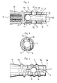
- the dental implants shown in figures have the particularity of presenting two front cutting edges for drilling calibrated implant pocket during which the material bone is stored inside these implants, and an external thread allowing a self-tapping.
- the dental implant shown in Figures 1 to 4 has a distal section tubular 1 having a cylindrical wall 2 of revolution around an axis defining an internal volume 3 storage of bone material.
- This cylindrical wall 2 has a distal end section 2a internally chamfered conferring a flared tapered shape to the portion lower of the internal storage volume 3, and forming a helical annular transverse base 4 in diameter internal "d” and external diameter "d + 2e".
- This cylindrical wall 2 further comprises two distal notches 5, 6 arranged symmetrically from each other with respect to the longitudinal axis of the dental implant, each forming a cutting edge frontal 7, 8 to the right of the annular transverse base 4.
- each of the notches 5, 6 forms a leading face 5a, 6a inclined at an angle a of the order 4 to 10 degrees from the longitudinal axis of the implant, while the annular transverse base 4 has, between each of said notches, a shape helical forming, for each of said cutting edges front 7, 8, a draft face 4a, 4b, inclined by angle ⁇ of the order of 4 to 10 degrees relative to a plane transverse.
- annular transverse base 4 is skewed so as to be inclined transversely in direction of the internal storage volume 3, at an angle 6 on the order of 4 to 10 degrees relative to a radial axis.
- the cylindrical wall 2 is also pierced orifices such as 9, 10 of secondary timing arranged two to two opposite each other symmetrically by relative to the longitudinal axis of the dental implant, and of which the axis of symmetry is not intersecting said longitudinal axis so that each of said orifices has an edge of complementary cut.
- each of these orifices 9, 10 is inclined in the opposite direction to the annular base 4, so as to cause the bone chips to penetrate naturally in the internal storage volume 3.
- the cylindrical wall 2 is also provided with an external thread 11 whose distal end starts above the notches 5, 6, presenting a progressive trapezoidal section of height increasing for the first nets 11a, and of shape triangular for the last nets 11b.
- threads 11a, 11b are spaced so as to delimit grooves 12 of trapezoidal section proportioned by the pitch and the height of the net.
- the peripheral wall 2 finally comprises two flutes 13, 14, in the example of section rectangular, arranged longitudinally in the extension of each of the notches 5, 6, and designed to each present a longitudinal cutting edge which initiates the self-tapping action of the thread external 11.
- flutes 13, 14 further extend over the length portion of the distal segment 1 provided with a external thread 11 of "truncated" section intended for self-tapping.
- the dental implant shown in Figures 1 to 4 further comprises a proximal section 15 of shape flared tapered, pierced with an axial imprint 16 of depth less than that of said proximal section of so that the bottom of said footprint is separated from the volume internal storage 3 by a material thickness 17.
- This imprint 16 has the form of a star, for example of the type of fingerprints known under the name "TORQ”, inscribed in a circle, and whose areas of material forming the branches and delimited by the circumscribing circle, are tapped.
- TORQ the type of fingerprints known under the name "TORQ”
- this imprint 16 presents a shape adapted to cooperate with a shaped tool of a conjugate star for the placement of the implant, and forms a threaded upper orifice capable of allowing the placement of a stump.
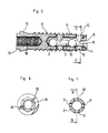
- the dental implant shown in Figures 5 to 7, meanwhile, has a distal section of identical structure to that of the implant described above (for this purpose and for simplification purposes, the same reference numbers will be used to designate similar elements of the two implant variants).
- This dental implant therefore includes mainly: a cylindrical wall 2 delimiting a internal storage volume 3, the end of which distal has two notches 5, 6 and forms a base helical ring 4 with two cutting edges frontal such as 8 to the right of said notches, secondary timing holes 9, 10 (in the example in number eight), one external thread 11 and two flutes 13, 14.
- This dental implant also includes a proximal section 15 of tapered flared shape.
- this section proximal 15 includes, such as some of the implants current, a threaded axial bore 18 for the installation place of a stump, and a head 19 of hexagonal shape.
- the drill 20 intended to carry out the implant implant pre-lodge in place of a dental implant according to the invention is a twist drill having two twisted grooves, and consisting of a distal section 21 of diameter included between "d” and "d + 2e", of a proximal section 22 of diameter "d + 2e", and an upper frustoconical section 23 of form the proximal head 15 of the implants, extended conventionally by a tail 24 for attachment to a tool.
- such a drill will present a distal section 21 of a 2.8 mm diameter, and a proximal section 22 with a diameter 3.4 mm.
- Figure 10 shows the pre-lodge implant 25 obtained by means of such a drill 20, after possibly preliminary realization of a pre-drilling by example using a drill with a diameter of 2 mm, having an upper flare 25a, an upper bore 25b with a diameter of 3.4 mm in the cortical part of the bone, and in the extension of the latter, a bore lower 25c with a diameter of 2.8 mm.
- this implant has an action self-tapping initiated by the longitudinal cutting edge flutes 13 and 14 and produced by threading external 11.
- the proximal section 15 of the implant is housed in the flare 25a in intimate contact with the bone.
- this implant allows, through the creation of an internal volume storage 3 suitable for housing bone material cut and whose dimensions can be for this purpose easily determined (possibly taking into account the storage volume of the timing holes secondary 9, 10 and flutes 13, 14), to obtain a intimate contact with the bone and optimal primary stability without causing compression of the bone material cut out.
Landscapes
- Health & Medical Sciences (AREA)
- Animal Behavior & Ethology (AREA)
- Orthopedic Medicine & Surgery (AREA)
- Dentistry (AREA)
- Epidemiology (AREA)
- Life Sciences & Earth Sciences (AREA)
- Oral & Maxillofacial Surgery (AREA)
- General Health & Medical Sciences (AREA)
- Public Health (AREA)
- Veterinary Medicine (AREA)
- Dental Prosthetics (AREA)
- Materials For Medical Uses (AREA)
- Dental Tools And Instruments Or Auxiliary Dental Instruments (AREA)
Claims (17)
- Chirurgische Ausrüstung für die Zahnimplantologie, die ein Bohrinstrument und ein endoknöchernes Zahnimplantat aufweist, dadurch gekennzeichnet, dass:das endoknöcherne Zahnimplantatein proximales Teilstück (15) aufweist, das ein Kooperationselement (16; 19) für ein Werkzeug zum Einsetzen des Implantats und eine obere, mit einem Innengewinde versehene, zur Aufnahme eines Stumpfes angepasste Öffnung (16; 18)ein distales, röhrenförmiges Teilstück (1) aufweist, das eine zylindrische Wandung (2) zur Rotation um eine ein internes Volumen (3) zur Aufnahme der Knochenmaterial begrenzende Achse umfasst, und das unter Bildung einer transversalen, ringförmigen Basis (4) mit einem internen Durchmesser "d" und einem externen Durchmesser "d+2e" ein distales Ende mit einer Dickte "e" darstellt, wobei die zylindrische Wandung mindestens eine distale Einbuchtung (5, 6) aufweist, die an die ringförmige Basis (4) eine frontseitige Schnittkante (7, 8) bildet, und die durch die ringförmige Basis und eine der Flächen (5a, 6a) der Einbuchtung begrenzt ist, wobei diese Flächen solcherart angepasst sind, dass sie jeweils eine Freifläche (4a, 4b) und eine Angriffsfläche (5a, 6a) bestimmen,ein Außengewinde (11), das mindestens eine distale Schnittkante (13, 14) aufweist, und das auf dem Zahnimplantat ausgespart ist und in Abstand der ringförmigen Basis (4) des distalen Teilstücks (1) beginnt,das Bohrinstrument einen Stufenbohrer (20) enthält, der ein distales Teilstück (21) mit einem Durchmesser zwischen "d" und "d+2e" und ein proximales Teilstück (22) mit einem Durchmesser von mindestens gleich "d+2e" und geringer als der externe Durchmesser des Gewindes (11) des Zahnimplantats aufweist.
- Chirurgische Ausrüstung gemäß Anspruch 1, dadurch gekennzeichnet, daß:das proximale Teilstück (15) des Zahnimplantats einen ausgeweiteten oberen Endabschnitt aufweist, der eine kegelstumpfförmige Form darstellt,der Stufenbohrer (20) ein das proximale Teilstück (22) verlängendes, oberes, kegelstumpfförmiges Teilstück (23) aufweist, deren Form derjenigen des Zahnimplantats zugeordnet ist.
- Endoknöchernes Zahnimplantat, dadurch gekennzeichnet, dass esein proximales Teilstück (15) aufweist, das ein Kooperationselement (16; 19) für ein Werkzeug zum Einsetzen des Implantats und eine obere, mit einem Innengewinde versehene, zur Aufnahme eines Stumpfes angepasste Öffnung (16; 18)ein distales, röhrenförmiges Teilstück (1) aufweist, das eine zylindrische Wandung (2) zur Rotation um eine ein internes Volumen (3) zur Aufnahme der Knochenmaterial begrenzende Achse umfasst, und das unter Bildung einer transversalen, ringförmigen Basis (4) mit einem internen Durchmesser "d" und einem externen Durchmesser "d+2e" ein distales Ende mit einer Dickte "e" darstellt, wobei die zylindrische Wandung mindestens eine distale Einbuchtung (5, 6) aufweist, die an die ringförmige Basis (4) eine frontseitige Schnittkante (7, 8) bildet, und die durch die ringförmige Basis und eine der Flächen (5a, 6a) der Einbuchtung begrenzt ist, wobei diese Flächen solcherart angepasst sind, dass sie jeweils eine eine Freifläche (4a, 4b) und eine Angriffsfläche (5a, 6a) bestimmen,ein Außengewinde (11), das mindestens eine distale Schnittkante (13, 14) aufweist, und das auf dem Zahnimplantat ausgespart ist und in Abstand der ringförmigen Basis (4) des distalen Teilstücks (1) beginnt.
- Zahnimplantat gemäß Anspruch 3, dadurch gekennzeichnet, dass es einen oberen Endabschnitt (15) aufweist, der eine kegelstumpfförmige Form darstellt.
- Zahnimplantat gemäß einem der Ansprüche 3 oder 4, dadurch gekennzeichnet, dass die zylindrische Wandung (2) des distalen Teilstücks (1) ein distales, schräges, transversal in Richtung des inneren, durch die periphere Wandung begrenzten Volumens (3) geneigtes Ende aufweist, das eine ringförmige Basis (4) bildet.
- Zahnimplantat gemäß einem der Ansprüche 3 bis 5, dadurch gekennzeichnet, dass das interne Volumen zur Aufnahme (3) ausgehend von der ringförmigen Basis (4) einen Volumenabschnitt (2a) in kegelstumpfförmiger Form aufweist, der sich in Richtung der ringförmigen Basis erweitert.
- Zahnimplantat gemäß einem der Ansprüche 3 bis 6, dadurch gekennzeichnet, dass die zylindrische Wandung (2) des distalen Teilstücks (1) zwei symmetrisch, in Bezug auf die longitudinale Achse des Zahnimplantats gegenüber angebrachte Einbuchtungen (5, 6) umfasst, wobei die ringförmig Basis (4) zwischen jeder Einbuchtung eine schraubenförmige Form aufweist und eine Freifläche (4a, 4b) für jede frontseitige Schnittkante (7, 8) bildet.
- Zahnimplantat gemäß einem der Ansprüche 3 bis 7, dadurch gekennzeichnet, dass die zylindrische Wandung (2) des distalen Teilstücks (1) mindestens einen longitudinalen Einschnitt (13, 14) aufweist, der auf der äußeren Seite der Wandung angebracht ist, wobei der longitudinale Einschnitt einen Queschnitt aufweist, der so angepesst ist, um eine longitudinale Schnittkante zu bilden.
- Zahnimplantat gemäß Anspruch 8, dadurch gekennzeichnet, dass jeder Einschnitt (13, 14) sich von der ringförmigen Basis (4) der zylindrischen Wandung (2) ausgehend erstreckt und in Bezug auf jede Einbuchtung (5, 6) winkelig verschoben ist.
- Zahnimplantat gemäß Anspruch 8, dadurch gekennzeichnet, dass jeder Einschnitt (13, 14) sich in der Verlängerung einer Einbuchtung (5, 6) erstreckt.
- Zahnimplantat gemäß einem der Ansprüche 3 bis 10, dadurch gekennzeichnet, dass das Außengewinde (11) ausgehend von seinem distalen Ende ersten Schraubenwindungen (11a) von trapezoidem Querschnitt aufweist und durch Schraubenwindungen (11b) von dreieckigem Querschnitt weitergeführt sind und dabei ein Gewinde von progressivem Querschnitt formt.
- Zahnimplantat gemäß Anspruch 11, dadurch gekennzeichnet, dass die Schraubenwindungen (11a, 11b) des Außengewindes (11) solcherart auseinandergerückt sind, um die Rillen (12) des trapezoiden Abschnittes zu begrenzen.
- Zahnimplantat gemäß einem der Ansprüche 3 bis 12, dadurch gekennzeichnet, dass die zylindrische Wandung (2) des distalen Teilstücks (1) Öffnungen (9; 10) zur sekundären, kreisförmigen Verkeilung aufweist, deren Achse in Bezug auf die Rotationsachse des Implantats nicht schneidend ist.
- Zahnimplantat gemäß Anspruch 13, dadurch gekennzeichnet, dass jede Öffnung zur sekundären Verkeilung (9, 10) in Richtung des proximalen Teilstücks (15) des Zahnimplantats geneigt ist.
- Zahnimplantat gemäß einem der Ansprüche 3 bis 14, dadurch gekennzeichnet, dass das Kooperationselement des proximalen Teilstücks (15) aus einem Kopf (19) mit einem polygonalen Querschnitt besteht.
- Zahnimplantat gemäß einem der Ansprüche 3 bis 14, dadurch gekennzeichnet, dass die obere Öffnung aus einem Innengewindeabdruck (16) besteht, der so ausgebildet ist, um gleichermaßen als Reservation zu dienen und angepasst ist, um mit einem Werkzeug zum Einsetzen des Implantats zusammenzuwirken.
- Chirurgische Ausrüstung, dadurch gekennzeichnet, dass sie ein Zahnimplantat umfasst, wie in einem der Ansprüche 3 bis 16 bestimmt.
Applications Claiming Priority (3)
| Application Number | Priority Date | Filing Date | Title |
|---|---|---|---|
| FR9506627 | 1995-05-30 | ||
| FR9506627A FR2734707B1 (fr) | 1995-05-30 | 1995-05-30 | Equipement chirurgical d'implantologie dentaire et elements, implant dentaire et instruments de forage, constitutifs |
| PCT/FR1996/000771 WO1996038098A1 (fr) | 1995-05-30 | 1996-05-23 | Equipement chirurgical d'implantologie dentaire et elements, implant dentaire et instruments de forage, constitutifs |
Publications (2)
| Publication Number | Publication Date |
|---|---|
| EP0825838A1 EP0825838A1 (de) | 1998-03-04 |
| EP0825838B1 true EP0825838B1 (de) | 2000-01-26 |
Family
ID=9479648
Family Applications (1)
| Application Number | Title | Priority Date | Filing Date |
|---|---|---|---|
| EP96917536A Expired - Lifetime EP0825838B1 (de) | 1995-05-30 | 1996-05-23 | Chirurgische ausrüstung für die zahnimplantologie, zahnimplantat, bohrinstrument und bestandteile |
Country Status (9)
| Country | Link |
|---|---|
| US (1) | US5871356A (de) |
| EP (1) | EP0825838B1 (de) |
| JP (1) | JPH11505757A (de) |
| AT (1) | ATE189110T1 (de) |
| CA (1) | CA2221057C (de) |
| DE (1) | DE69606402T2 (de) |
| ES (1) | ES2143762T3 (de) |
| FR (1) | FR2734707B1 (de) |
| WO (1) | WO1996038098A1 (de) |
Families Citing this family (44)
| Publication number | Priority date | Publication date | Assignee | Title |
|---|---|---|---|---|
| EP0678731B1 (de) * | 1994-04-15 | 1999-06-30 | Nissan Motor Co., Ltd. | Fahrzeug-Navigationssystem |
| US6402515B1 (en) * | 2001-01-10 | 2002-06-11 | Sulzer Dental Inc. | Dental implant with variable profile thread |
| SE520756C2 (sv) * | 2001-12-21 | 2003-08-19 | Nobel Biocare Ab | Förfarande för att åstadkomma ytstruktur på implantat samt sådant implantat |
| SE523395C2 (sv) * | 2001-12-21 | 2004-04-13 | Nobel Biocare Ab | Implantat och förfarande och system för tillhandahållande av sådant implantat |
| FR2836372B1 (fr) * | 2002-02-28 | 2004-06-04 | Obl | Procede et dispositif pour la mise en place d'implants dentaires |
| AU2003249979A1 (en) * | 2002-07-26 | 2004-02-23 | Star-Group-International | Dental implant comprising an anchoring head and a screw element |
| DE10251469B4 (de) * | 2002-11-05 | 2007-07-12 | Gebr. Brasseler Gmbh & Co. Kg | Zahnimplantat |
| SE526682C2 (sv) | 2002-12-19 | 2005-10-25 | Medevelop Ab | Fixtur för fastskruvning i benvävnad |
| SE526915C2 (sv) * | 2002-12-30 | 2005-11-15 | Nobel Biocare Ab | Borr användbart vid käkben med överliggande mjukvävnad |
| SE526667C2 (sv) * | 2002-12-30 | 2005-10-25 | Nobel Biocare Ab | Anordning vid implantat och förfarande för framställning av implantatet |
| JP4664274B2 (ja) | 2003-02-28 | 2011-04-06 | マテリアライズ・デンタル・ナムローゼ・フエンノートシャップ | 歯科上部構造を配置および製造するための方法、インプラントを配置するための方法、およびこれが用いる付属物 |
| US7059855B2 (en) * | 2003-03-05 | 2006-06-13 | Albert Zickman | Dental implant system |
| DE202004000723U1 (de) * | 2003-03-13 | 2004-04-08 | Thommen Medical Ag | Pilotbohrer, Stufenbohrer und Bohrerset für die Dentalimplantologie |
| IL156033A0 (en) | 2003-05-21 | 2004-03-28 | Ophir Fromovich Ophir Fromovic | Dental implant |
| US20050053897A1 (en) * | 2003-09-05 | 2005-03-10 | Wen-Yuen Wu | Structure of artificial implantable dental |
| GB0327822D0 (en) * | 2003-12-01 | 2003-12-31 | Materialise Nv | Method for manufacturing a prosthesis made prior to implant placement |
| US7845945B2 (en) * | 2004-01-28 | 2010-12-07 | Stanton R. Canter | Anchoring element for use in bone |
| AR043256A1 (es) * | 2004-02-20 | 2005-07-20 | Odontit S A | Una disposicion de implante dental integrado al hueso para sostener una protesis dental |
| SE0400546D0 (sv) * | 2004-03-05 | 2004-03-05 | Dan Lundgren | Rörformigt benförankringselement |
| DE102005038038A1 (de) * | 2005-08-09 | 2007-02-15 | Streckbein, Roland, Dr.Dr. | Werkzeuge zum Herstellen und Vorbereiten einer Bohrung zur Aufnahme von Zahnimplantaten und entsprechendes Zahnimplantat |
| GB0609988D0 (en) * | 2006-05-19 | 2006-06-28 | Materialise Nv | Method for creating a personalized digital planning file for simulation of dental implant placement |
| US20080085488A1 (en) * | 2006-08-29 | 2008-04-10 | Sargon Lazarof | Universal one-step drill |
| DE102008006094B4 (de) * | 2007-02-14 | 2014-05-08 | Bernhard Förster Gmbh | Orthodontisches Schraubimplantat sowie System aus orthodontischem Schraubimplantat und Drahtbogen |
| US8038442B2 (en) | 2007-04-23 | 2011-10-18 | Nobel Biocare Services Ag | Dental implant and dental component connection |
| US7806693B2 (en) | 2007-04-23 | 2010-10-05 | Nobel Biocare Services Ag | Dental implant |
| FR2922751A1 (fr) * | 2007-10-31 | 2009-05-01 | Tekka Sa | Implant dentaire et outil pour la preparation de la zone d'implantation. |
| DE102008010049B3 (de) * | 2008-02-20 | 2009-01-02 | Gebr. Brasseler Gmbh & Co. Kg | Dentalbohrer aus Kunststoff |
| EP2358293A1 (de) | 2008-09-10 | 2011-08-24 | Nobel Biocare Services AG | Vorrichtung und verfahren zum implantieren eines dentalimplantats |
| DE102009016920B4 (de) | 2009-04-08 | 2013-03-28 | Peter Metz-Stavenhagen | Dentalimplantat |
| KR101092311B1 (ko) * | 2009-05-13 | 2011-12-09 | 주식회사 메가젠임플란트 | 치과용 임플란트의 픽스츄어 |
| DE102009033138A1 (de) * | 2009-07-13 | 2011-02-03 | Z-Medical Gmbh & Co. Kg | Schraube zum Einsetzen in einen Knochen |
| EP2292175B1 (de) * | 2009-09-07 | 2016-08-17 | Nobel Biocare Services AG | Komponenten zum geführten Gewindeschneiden von Knochen |
| IL201115A0 (en) | 2009-09-23 | 2010-06-16 | Elkana Elyav Dr | Dental implant |
| KR101122134B1 (ko) * | 2011-07-11 | 2012-03-16 | 주식회사 메가젠임플란트 | 치과용 임플란트의 픽스츄어 |
| US9387027B2 (en) * | 2012-12-13 | 2016-07-12 | Jonathon Yigal Yahav | Implantable fixture |
| CN106535860B (zh) | 2014-04-11 | 2020-01-07 | 拜奥美特3i有限责任公司 | 具有高初级稳定性和加强的二级稳定性的种植体 |
| US10188489B2 (en) * | 2014-04-17 | 2019-01-29 | Star Generation Limited Taiwan Branch | Sinus implant |
| FR3024351B1 (fr) * | 2014-08-01 | 2021-11-19 | Ldr Medical | Implants osseux |
| CL2015001657S1 (es) | 2014-12-15 | 2016-09-02 | Jjgc Indústria E Comércio De Materiais Dentários S A | Configuracion aplicada a implante oseo. |
| BR102014031426B1 (pt) | 2014-12-15 | 2018-07-24 | Jjgc Ind E Comercio De Materiais Dentarios S/A | implante |
| WO2016207728A1 (en) * | 2015-06-23 | 2016-12-29 | The Research Foundation For The State University Of New York | Multi-diameter drill bit |
| BR102016010184B1 (pt) | 2016-05-05 | 2020-10-27 | Jjgc Indústria E Comércio De Materiais Dentários S.A. | conjunto protético e processo para produção do mesmo |
| US10188484B2 (en) | 2016-11-17 | 2019-01-29 | Jonathon Yigal Yahav | System of components or implements for easily and precisely installing a dental implant, and a method of installing the dental implant |
| KR102059960B1 (ko) * | 2018-06-11 | 2019-12-30 | 장희지 | 생분해성 물질을 구비한 임플란트 |
Family Cites Families (11)
| Publication number | Priority date | Publication date | Assignee | Title |
|---|---|---|---|---|
| DE2619650C3 (de) * | 1976-05-04 | 1985-06-05 | Friedrichsfeld Gmbh, Steinzeug- Und Kunststoffwerke, 6800 Mannheim | Dentalimplantat |
| US4431416A (en) * | 1982-04-29 | 1984-02-14 | A & L Investment Company | Endosseous dental implant system for overdenture retention, crown and bridge support |
| FR2571607B1 (fr) * | 1984-10-11 | 1988-10-14 | Texier Jean | Implant endo-osseux concu pour servir de pilier en bouche |
| FR2587197A1 (fr) * | 1985-09-13 | 1987-03-20 | Reynaud Marc | Tenon d'ancrage d'une prothese dentaire dans la racine d'une dent |
| US5061181A (en) * | 1987-01-08 | 1991-10-29 | Core-Vent Corporation | Dental implant including plural anchoring means |
| ES2004221A6 (es) * | 1987-02-13 | 1988-12-16 | Padros Pradera Alejandro | Tornillos para implantes dentales |
| IT1237496B (it) * | 1989-10-26 | 1993-06-08 | Giuseppe Vrespa | Dispositivo a vite per l'ancoraggio di protesi alle ossa, metodo per l'applicazione di tale dispositivo e relativa attrezzatura |
| US5312254A (en) * | 1993-03-26 | 1994-05-17 | Rosenlicht Joel L | Sterile application of implants in bone |
| US5366374A (en) * | 1993-05-18 | 1994-11-22 | Vlassis James M | Dental implant |
| US5642996A (en) * | 1993-10-20 | 1997-07-01 | Nikon Corporation | Endosseous implant |
| US5571017A (en) * | 1994-10-05 | 1996-11-05 | Core-Vent Corporation | Selective surface, externally-threaded endosseous dental implant |
-
1995
- 1995-05-30 FR FR9506627A patent/FR2734707B1/fr not_active Expired - Lifetime
-
1996
- 1996-05-23 ES ES96917536T patent/ES2143762T3/es not_active Expired - Lifetime
- 1996-05-23 JP JP8536243A patent/JPH11505757A/ja active Pending
- 1996-05-23 EP EP96917536A patent/EP0825838B1/de not_active Expired - Lifetime
- 1996-05-23 CA CA002221057A patent/CA2221057C/fr not_active Expired - Lifetime
- 1996-05-23 DE DE69606402T patent/DE69606402T2/de not_active Expired - Lifetime
- 1996-05-23 WO PCT/FR1996/000771 patent/WO1996038098A1/fr active IP Right Grant
- 1996-05-23 US US08/894,383 patent/US5871356A/en not_active Expired - Lifetime
- 1996-05-23 AT AT96917536T patent/ATE189110T1/de not_active IP Right Cessation
Also Published As
| Publication number | Publication date |
|---|---|
| CA2221057A1 (fr) | 1996-12-05 |
| EP0825838A1 (de) | 1998-03-04 |
| CA2221057C (fr) | 2007-04-24 |
| US5871356A (en) | 1999-02-16 |
| DE69606402T2 (de) | 2000-09-21 |
| DE69606402D1 (de) | 2000-03-02 |
| ATE189110T1 (de) | 2000-02-15 |
| ES2143762T3 (es) | 2000-05-16 |
| WO1996038098A1 (fr) | 1996-12-05 |
| FR2734707B1 (fr) | 1997-08-29 |
| JPH11505757A (ja) | 1999-05-25 |
| FR2734707A1 (fr) | 1996-12-06 |
Similar Documents
| Publication | Publication Date | Title |
|---|---|---|
| EP0825838B1 (de) | Chirurgische ausrüstung für die zahnimplantologie, zahnimplantat, bohrinstrument und bestandteile | |
| EP2032082B1 (de) | Schulterprothese und instrumentensatz zur implantierung | |
| EP0530160B1 (de) | Element zum Verankern | |
| EP1876992B1 (de) | Dentalimplantatvorrichtung | |
| FR2944692A1 (fr) | Materiel d'osteosynthese vertebrale | |
| CN102085113B (zh) | 骨螺钉 | |
| FR2787313A1 (fr) | Implant d'osteosynthese | |
| FR2801189A1 (fr) | Implant pour raccourcissement osseux, et en particulier, metatarsien | |
| LU87365A1 (fr) | Implant buccal | |
| EP0871419A1 (de) | Zwischenwirbelimplantat als wirbelkäfig ausgebildet | |
| EP1195146B1 (de) | Set für die Implantation eines Zahnimplantates | |
| EP0637228A1 (de) | Mehrere teile aufweisendes dentales implantat sowie zubehör dafür | |
| KR100906692B1 (ko) | 상악동 내 골막 거상술용 안전드릴조립체 | |
| WO2003015642A1 (fr) | Ensemble pour la mise en place d'un implant femoral de prothese de hanche sur un femur | |
| WO2011036655A1 (en) | Medical drill system and method for using thereof | |
| FR2571607A1 (fr) | Implant endo-osseux concu pour servir de pilier en bouche | |
| FR2737847A1 (fr) | Implant-taraud comprimant | |
| EP4132390B1 (de) | Leicht entfernbares knochenverankerungsimplantat | |
| EP4132391B1 (de) | Kortikal stabilisiertes knochenverankerungsimplantat | |
| FR2788215A1 (fr) | Implant-vis a filetage a ancrage endo-osseux | |
| JPH11151253A (ja) | 義歯を人間の顎に保持するための歯科医術用上部構造のための顎インプラント | |
| FR3000662A3 (fr) | Vis a os auto-foreuse et auto-taraudeuse | |
| EP0437401B1 (de) | Chirurgisches Implant für Mund- und Kieferimplantationen | |
| EP0278887B1 (de) | Dentales Implantat zur Verankerung von Prothesen | |
| WO2014203149A1 (fr) | Dispositif implantable de chirurgie dentaire |
Legal Events
| Date | Code | Title | Description |
|---|---|---|---|
| PUAI | Public reference made under article 153(3) epc to a published international application that has entered the european phase |
Free format text: ORIGINAL CODE: 0009012 |
|
| 17P | Request for examination filed |
Effective date: 19971117 |
|
| AK | Designated contracting states |
Kind code of ref document: A1 Designated state(s): AT BE CH DE DK ES FI FR GB GR IE IT LI LU MC NL PT SE |
|
| GRAG | Despatch of communication of intention to grant |
Free format text: ORIGINAL CODE: EPIDOS AGRA |
|
| 17Q | First examination report despatched |
Effective date: 19990205 |
|
| GRAG | Despatch of communication of intention to grant |
Free format text: ORIGINAL CODE: EPIDOS AGRA |
|
| GRAH | Despatch of communication of intention to grant a patent |
Free format text: ORIGINAL CODE: EPIDOS IGRA |
|
| GRAH | Despatch of communication of intention to grant a patent |
Free format text: ORIGINAL CODE: EPIDOS IGRA |
|
| GRAA | (expected) grant |
Free format text: ORIGINAL CODE: 0009210 |
|
| AK | Designated contracting states |
Kind code of ref document: B1 Designated state(s): AT BE CH DE DK ES FI FR GB GR IE IT LI LU MC NL PT SE |
|
| PG25 | Lapsed in a contracting state [announced via postgrant information from national office to epo] |
Ref country code: SE Free format text: THE PATENT HAS BEEN ANNULLED BY A DECISION OF A NATIONAL AUTHORITY Effective date: 20000126 Ref country code: NL Free format text: LAPSE BECAUSE OF FAILURE TO SUBMIT A TRANSLATION OF THE DESCRIPTION OR TO PAY THE FEE WITHIN THE PRESCRIBED TIME-LIMIT Effective date: 20000126 Ref country code: GR Free format text: LAPSE BECAUSE OF NON-PAYMENT OF DUE FEES Effective date: 20000126 Ref country code: FI Free format text: LAPSE BECAUSE OF FAILURE TO SUBMIT A TRANSLATION OF THE DESCRIPTION OR TO PAY THE FEE WITHIN THE PRESCRIBED TIME-LIMIT Effective date: 20000126 Ref country code: AT Free format text: LAPSE BECAUSE OF FAILURE TO SUBMIT A TRANSLATION OF THE DESCRIPTION OR TO PAY THE FEE WITHIN THE PRESCRIBED TIME-LIMIT Effective date: 20000126 |
|
| REF | Corresponds to: |
Ref document number: 189110 Country of ref document: AT Date of ref document: 20000215 Kind code of ref document: T |
|
| REG | Reference to a national code |
Ref country code: CH Ref legal event code: EP |
|
| REF | Corresponds to: |
Ref document number: 69606402 Country of ref document: DE Date of ref document: 20000302 |
|
| REG | Reference to a national code |
Ref country code: IE Ref legal event code: FG4D Free format text: FRENCH |
|
| ITF | It: translation for a ep patent filed |
Owner name: DOTT. ING. FRANCO RASTELLI |
|
| PG25 | Lapsed in a contracting state [announced via postgrant information from national office to epo] |
Ref country code: PT Free format text: LAPSE BECAUSE OF FAILURE TO SUBMIT A TRANSLATION OF THE DESCRIPTION OR TO PAY THE FEE WITHIN THE PRESCRIBED TIME-LIMIT Effective date: 20000426 Ref country code: DK Free format text: LAPSE BECAUSE OF FAILURE TO SUBMIT A TRANSLATION OF THE DESCRIPTION OR TO PAY THE FEE WITHIN THE PRESCRIBED TIME-LIMIT Effective date: 20000426 |
|
| REG | Reference to a national code |
Ref country code: ES Ref legal event code: FG2A Ref document number: 2143762 Country of ref document: ES Kind code of ref document: T3 |
|
| GBT | Gb: translation of ep patent filed (gb section 77(6)(a)/1977) |
Effective date: 20000425 |
|
| PG25 | Lapsed in a contracting state [announced via postgrant information from national office to epo] |
Ref country code: LU Free format text: LAPSE BECAUSE OF NON-PAYMENT OF DUE FEES Effective date: 20000523 |
|
| PG25 | Lapsed in a contracting state [announced via postgrant information from national office to epo] |
Ref country code: LI Free format text: LAPSE BECAUSE OF NON-PAYMENT OF DUE FEES Effective date: 20000531 Ref country code: CH Free format text: LAPSE BECAUSE OF NON-PAYMENT OF DUE FEES Effective date: 20000531 |
|
| NLV1 | Nl: lapsed or annulled due to failure to fulfill the requirements of art. 29p and 29m of the patents act | ||
| PLBE | No opposition filed within time limit |
Free format text: ORIGINAL CODE: 0009261 |
|
| STAA | Information on the status of an ep patent application or granted ep patent |
Free format text: STATUS: NO OPPOSITION FILED WITHIN TIME LIMIT |
|
| PG25 | Lapsed in a contracting state [announced via postgrant information from national office to epo] |
Ref country code: MC Free format text: LAPSE BECAUSE OF NON-PAYMENT OF DUE FEES Effective date: 20001130 |
|
| 26N | No opposition filed | ||
| REG | Reference to a national code |
Ref country code: CH Ref legal event code: PL |
|
| REG | Reference to a national code |
Ref country code: GB Ref legal event code: IF02 |
|
| PG25 | Lapsed in a contracting state [announced via postgrant information from national office to epo] |
Ref country code: IT Free format text: LAPSE BECAUSE OF NON-PAYMENT OF DUE FEES Effective date: 20050523 |
|
| REG | Reference to a national code |
Ref country code: FR Ref legal event code: PLFP Year of fee payment: 20 |
|
| PGFP | Annual fee paid to national office [announced via postgrant information from national office to epo] |
Ref country code: GB Payment date: 20150506 Year of fee payment: 20 Ref country code: DE Payment date: 20150424 Year of fee payment: 20 Ref country code: ES Payment date: 20150424 Year of fee payment: 20 |
|
| PGFP | Annual fee paid to national office [announced via postgrant information from national office to epo] |
Ref country code: IE Payment date: 20150424 Year of fee payment: 20 Ref country code: FR Payment date: 20150424 Year of fee payment: 20 |
|
| PGFP | Annual fee paid to national office [announced via postgrant information from national office to epo] |
Ref country code: BE Payment date: 20150430 Year of fee payment: 20 |
|
| REG | Reference to a national code |
Ref country code: DE Ref legal event code: R071 Ref document number: 69606402 Country of ref document: DE |
|
| REG | Reference to a national code |
Ref country code: GB Ref legal event code: PE20 Expiry date: 20160522 |
|
| REG | Reference to a national code |
Ref country code: IE Ref legal event code: MK9A |
|
| PG25 | Lapsed in a contracting state [announced via postgrant information from national office to epo] |
Ref country code: IE Free format text: LAPSE BECAUSE OF EXPIRATION OF PROTECTION Effective date: 20160523 Ref country code: GB Free format text: LAPSE BECAUSE OF EXPIRATION OF PROTECTION Effective date: 20160522 |
|
| REG | Reference to a national code |
Ref country code: ES Ref legal event code: FD2A Effective date: 20160830 |
|
| PG25 | Lapsed in a contracting state [announced via postgrant information from national office to epo] |
Ref country code: ES Free format text: LAPSE BECAUSE OF EXPIRATION OF PROTECTION Effective date: 20160524 |