EP0825713A2 - Filtre couplée transversalement et méthode à ondes acoustiques de surface comportant une entrée différentielle et/ou une sortie différentielle - Google Patents
Filtre couplée transversalement et méthode à ondes acoustiques de surface comportant une entrée différentielle et/ou une sortie différentielle Download PDFInfo
- Publication number
- EP0825713A2 EP0825713A2 EP97113082A EP97113082A EP0825713A2 EP 0825713 A2 EP0825713 A2 EP 0825713A2 EP 97113082 A EP97113082 A EP 97113082A EP 97113082 A EP97113082 A EP 97113082A EP 0825713 A2 EP0825713 A2 EP 0825713A2
- Authority
- EP
- European Patent Office
- Prior art keywords
- electrodes
- group
- disposing
- transducer
- coupled
- Prior art date
- Legal status (The legal status is an assumption and is not a legal conclusion. Google has not performed a legal analysis and makes no representation as to the accuracy of the status listed.)
- Withdrawn
Links
Images


Classifications
-
- H—ELECTRICITY
- H03—ELECTRONIC CIRCUITRY
- H03H—IMPEDANCE NETWORKS, e.g. RESONANT CIRCUITS; RESONATORS
- H03H9/00—Networks comprising electromechanical or electro-acoustic devices; Electromechanical resonators
- H03H9/46—Filters
- H03H9/64—Filters using surface acoustic waves
- H03H9/6423—Means for obtaining a particular transfer characteristic
- H03H9/6433—Coupled resonator filters
-
- H—ELECTRICITY
- H03—ELECTRONIC CIRCUITRY
- H03H—IMPEDANCE NETWORKS, e.g. RESONANT CIRCUITS; RESONATORS
- H03H9/00—Networks comprising electromechanical or electro-acoustic devices; Electromechanical resonators
- H03H9/0023—Balance-unbalance or balance-balance networks
- H03H9/0028—Balance-unbalance or balance-balance networks using surface acoustic wave devices
- H03H9/0047—Balance-unbalance or balance-balance networks using surface acoustic wave devices having two acoustic tracks
- H03H9/0052—Balance-unbalance or balance-balance networks using surface acoustic wave devices having two acoustic tracks being electrically cascaded
- H03H9/0057—Balance-unbalance or balance-balance networks using surface acoustic wave devices having two acoustic tracks being electrically cascaded the balanced terminals being on the same side of the tracks
-
- H—ELECTRICITY
- H03—ELECTRONIC CIRCUITRY
- H03H—IMPEDANCE NETWORKS, e.g. RESONANT CIRCUITS; RESONATORS
- H03H9/00—Networks comprising electromechanical or electro-acoustic devices; Electromechanical resonators
- H03H9/46—Filters
- H03H9/64—Filters using surface acoustic waves
- H03H9/6423—Means for obtaining a particular transfer characteristic
- H03H9/6433—Coupled resonator filters
- H03H9/644—Coupled resonator filters having two acoustic tracks
- H03H9/6456—Coupled resonator filters having two acoustic tracks being electrically coupled
- H03H9/6459—Coupled resonator filters having two acoustic tracks being electrically coupled via one connecting electrode
- H03H9/6463—Coupled resonator filters having two acoustic tracks being electrically coupled via one connecting electrode the tracks being electrically cascaded
Definitions
- This invention pertains to microelectronic devices employing acoustic waves and more particularly to differential input, differential output, transversely-coupled surface acoustic wave (SAW) filters.
- SAW surface acoustic wave
- FIG. 1 illustrates the configuration of electrodes 14 of single pole SAW resonator 10 in accordance with the prior art.
- FIG. 1 illustrates acoustic wave propagating substrate 11 having pattern 19 disposed thereon.
- SAW resonator 10 has single-ended input terminal 15 referenced to ground terminal 15'.
- Pattern 19 usefully comprises bus bars 12, 12' connected to a series of electrode fingers 14. Electrode fingers 14 and bus bars 12, 12' together form transducer 16.
- Transducer 16 is disposed along a preferred axis of the substrate material and on a suitably prepared surface thereof.
- Transducer 16 comprises a series of periodically disposed electrode fingers 14, often one-fourth of an acoustic wavelength in width, disposed on one-half acoustic wavelength centers, usually alternately coupled to associated bus bars 12, 12', although other arrangements are possible and useful.
- Electrical stimulation applied to terminal 15 i.e., across bus bars 12, 12'
- Transducers such as transducer 16 typically launch acoustic waves in directions 30, 31 when excited by electrical signals of appropriate frequency at bus bars such as 12, 12' and typically manifest electrical signals at the bus bars when insonified by acoustic waves of appropriate frequency traveling along directions 30 and/or 31.
- Resonators of this type typically include at least two reflectors 18, 18' and at least one transducer 16 disposed between reflectors 18, 18', collectively forming first track 13. Another important design feature in FIG. 1 are gaps 20 disposed between reflectors 18, 18' and transducer 16. Gaps 20 typically have a width exceeding one-fourth of the acoustic wavelength.
- FIG. 2 illustrates a plan view of transversely-coupled resonator 100, formed by placing two single-pole SAW resonators in close proximity in accordance with the prior art.
- Acoustic wave propagating substrate 11 has pattern 119 disposed thereon.
- Transversely-coupled SAW resonator 100 includes input terminal 15, grounded terminal 15', output terminal 17 and grounded terminal 17'.
- Pattern 119 usefully comprises bus bars 112, 112' connected to a series of electrode fingers 114. Electrode fingers 114, input bus bar 112 and grounded electrode fingers 113 form transducer 116. Similarly, electrode fingers 114', output bus bar 112' and grounded electrode fingers 113' form transducer 116'.
- Transducers 116, 116' are disposed along a preferred axis of the substrate material and on a suitably prepared surface thereof.
- Resonators of this type typically include at least two reflectors 118, 118' and at least one transducer 116 or 116' disposed between reflectors 118, 118' or 117, 117', respectively.
- Another important design feature in FIG. 2 are gaps 200 disposed between reflectors 118, 118' and transducer(s) 116, 116'. Gaps 200 typically have a width exceeding one-fourth of an acoustic wavelength.
- Transducer 116 and reflector gratings 118, 118' together form first track 13 and transducer 116' and reflector gratings 117, 117' together form second track 13' of transversely-coupled SAW resonator 100.
- Electrical stimulation impressed on terminal 15 at an appropriate frequency causes acoustic energy in first track 13. This energy is transversely coupled to second track 13' and is finally converted to electrical energy at terminal 17.
- FIG. 3 illustrates another embodiment of prior art two-pole transversely-coupled SAW filter 300.
- terminal 15 couples electrical signals into bus bar 312 and these are converted to acoustic energy via transducer 316.
- This acoustic energy in first track 13 couples to second track 13' and is in turn converted to electrical energy via transducer 316', which is electrically coupled to bus bar 312' and terminal 17.
- transducer 316' It is known in the art to ground both 15' and 17' at a common ground location.
- the frequency dependence of the efficiency of conversion of electrical energy to acoustic energy is determined primarily by the configuration of transducers 316, 316' and reflectors 318, 318' and this frequency dependence gives rise to a transfer function having useful filtering properties.
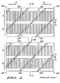
- FIG. 4 illustrates a simplified plan view of a transversely-coupled four-pole SAW filter having a single input terminal and a single output terminal in accordance with the prior art.
- Prior art four-pole transversely-coupled SAW filters are manufactured by joining together pairs of prior art two-pole transversely-coupled SAW filters with a single electrical coupling trace 400.
- Substrates 11 of ST-cut quartz having cut angles in the range of 32-42+° are preferred for some applications.
- Filter patterns are typically fabricated by depositing and patterning a thin metal film, often comprising aluminum in a thickness ranging from a few tens to a few hundreds of nanometers thick, by techniques similar to those employed in integrated circuit manufacturing.
- Basic single-pole SAW resonator 10 (FIG. 1) typically contains transducer 16 including interdigitated electrode fingers 14 disposed between reflective gratings 18, 18'.
- Transversely-coupled resonator filters 100, 300 offer narrow-band filtering of signals present at input terminals 15, 15' to provide output signals at output terminals 17, 17'.
- This type of transversely-coupled resonator filter offers single layer fabrication, steep skirted filtering with superior close-in rejection. For this reason, transversely-coupled SAW filters are frequently being used as narrow-bandwidth intermediate frequency filters suitable for use in current cellular telephone design configurations.
- the transversely coupled resonator filter geometry does not readily lend itself to operate in a balanced (differential) input and/or balanced (differential) output configuration.
- the balanced configuration is oftentimes highly desirable from a design perspective.
- a balanced configuration is understood to mean equal impedances between the positive lead and ground and the negative lead and ground. Nevertheless, there are increasing demands from designers in the telecommunications industry for Surface Acoustic Wave (SAW) filters able to operate with differential input and/or output terminations.
- SAW Surface Acoustic Wave
- SAW filter could be designed with differential input, and/or differential output, terminal configurations, this SAW filter could then be placed directly in line with other electronic components such as a balanced or double balanced mixer or a balanced amplifier, for example, in a cellular telephone.
- Such SAW filter designs eliminate need for other components such as transformers or baluns, reducing the overall number of components in the final product and results in other benefits such as lighter weight, reduced size and less power consumption.
- SAW Surface Acoustic Wave
- FIG. 5 illustrates one application of differential SAW transducer 516' in a coupled resonator filter but it will be apparent to those of skill in the relevant arts that such transducers may be employed in other types of SAW devices and that single transducers not acoustically coupled to other transducers find utility as frequency-dependent impedances in such applications as frequency-selection components and notch filters.
- FIGs. 5-10 illustrate novel designs in accordance with the present invention employing differential input and/or output, transversely-coupled SAW resonators.
- FIG. 5 illustrates a first embodiment of the present invention applied to two-pole transversely-coupled filter 500 having single-ended input terminal 15 and differential output terminals 17+, 17- with a common ground terminal.
- This design can be incorporated into the design of electronic equipment such as a portable cellular telephone in such a manner as to lower the total number of components, reducing both weight and size.
- this invention is not limited to cellular telephone designs but could also be in incorporated into any piece of electronic equipment which uses SAW filters.
- First track 13 comprises single-ended input transducer 516 having terminal 15 and reflectors 318, 318' whereas second track 13' comprises differential transducer 516' having terminations 17+, 17-, ground and reflectors 317, 317'.
- Groups 514', 514'' are spatially separated in phase by an extra half of an acoustic wavelength and ground electrodes 519, 520 are also offset by an extra half of an acoustic wavelength.
- electrodes 514', 519 form a first set of comb electrodes having electrodes 519 coupled to a common or ground node offset by half of an acoustic wavelength (or any integral multiple thereof) from electrodes 520 also coupled to the common or ground electrode, where electrodes 520 are included in a second set of comb electrodes comprising electrodes 514'', 520.
- Filter 500 converts signals from unbalanced to a balanced conditions (or vice versa) for a variety of electronic design applications while simultaneously providing a filtering function. "Coupled Resonator Filters With Differential Input And/Or Differential Output" by M.A. Sharif et al., pp.
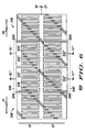
- FIG. 6 illustrates a second embodiment of the present invention applied to a two-pole transversely-coupled filter in which tracks 13, 13' have differential input terminals 15+, 15- and differential output terminals 17+, 17- with a common ground terminal.
- transducers 616, 616' were designed to provide differential input and differential output.
- Filter 600 has input terminals 15+, 15- and output terminals 17+, 17-, providing balanced input, balanced output, two-pole transversely-coupled SAW filter 600.
- input terminal 15+ couples to first set of electrodes 514' while input terminal 15- couples, via bus bar 512'' to second set of electrodes 514'' separated from first group of electrodes 514' by a multiple of acoustic half wavelengths and ground electrodes 519, 520 are also offset by an extra half of an acoustic wavelength.
- Reflectors 318, 318' bound both first and second tracks 13, 13'.
- Second track 13' includes output terminal 17+ coupled to first group of electrodes 514' via bus bar 512' and output terminal 17- coupled to second group of electrodes 514'' separated from first group of electrodes 514' by a multiple of acoustic half wavelengths and ground electrodes 519, 520 are also offset by an extra half of an acoustic wavelength.
- First and second tracks 13, 13' are each typically only a few acoustic wavelengths broad (vertical axis, FIG. 6) and accordingly support acoustic propagation modes having significant energy content outside of first and second tracks 13, 13'.
- a seven wavelength breadth or aperture was employed together with a separation between tracks of 0.9 wavelength, for a center to center separation of 7.9 wavelengths.
- First and second tracks 13, 13' are usefully in a range of from four to thirteen wavelengths broad, desirably in a range of from seven to ten wavelengths broad and preferably are about eight to nine wavelengths broad, depending on design bandwidth.
- first track 13 In operation, electrical stimulation having appropriate frequency and phase applied to input terminals 15+, 15- results in acoustic energy being manifested in first track 13.
- Reflectors 318, 318' form a resonant cavity much like a Fabry-Perot cavity and this serves to trap acoustic energy in first track 13 along the horizontal axis.
- This energy is partially coupled into second track 13' by the close physical proximity of the two tracks, typically one-half to three wavelengths, and the fact that the acoustic modes of the two tracks overlap spatially to provide new acoustic modes for the combined structure.
- Acoustic energy in second track 13' gives rise to electrical energy being manifested at terminals 17+, 17-.
- the transfer functions of transducers 616, 616', first and second tracks 13, 13' and of the acoustic coupling combine to provide the overall frequency response of filter 600.
- the ground connection between the two halves of filter 600 may be broken at the center of filter 600 (i.e., vertically through the central electrode running along the common border of tracks 13, 13').
- input ground may be isolated from output ground by omitting a central stripe of metallization in the electrode running along the common border between tracks 13, 13' (horizontally in FIG. 6).
- the new design according to the present invention may also be applied to four-pole transversely-coupled filters.
- four-pole transversely-coupled filters typically, by adding two more resonators to the two-pole transversely-coupled SAW filter design, an electrical frequency response with an improved profile having large out-of-band rejection can be achieved.
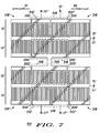
- FIGs. 7, 8 provide some examples showing how the novel termination design according to the present invention may be applied to four-pole SAW filter designs.
- FIG. 7 illustrates a third embodiment of the present invention in which four pole filter 701 combines a pair of structures like that of filter 500 (FIG. 5) via interconnection 700 to provide improved performance (e.g., increased out-of-band rejection, steeper skirts etc.) than is achieved by filter 500.
- grounds between first and second tracks 13, 13' need not be common (i.e., the tracks may employ different grounds)
- an interconnection (not illustrated but implied by common grounds 15', 17') analogous to interconnection 700 may be provided between second tracks 13', 13' for improved operation, although this ground connection may be external to filter 701.
- Having a common ground, as illustrated, has the overall effect of minimizing the normally required tuning inductor(s) to a single inductor coupled between terminal 700 and ground. In the event of sufficiently long transducers 516, no inductor is required at terminal 700.
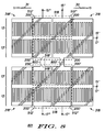
- FIG. 8 illustrates a fourth embodiment of the present invention in which four-pole transversely-coupled SAW filter 801 is formed having a dual coupling track between the resonator pairs.
- This design is similar to filter 701 (FIG. 7) in that it has differential input terminals 15+, 15- and differential output terminals 17+, 17-, however, the actual transducer designs differ.
- Filter 801, having dual electrical coupling tracks 800, 800' also employs correspondingly different transducers 518, 518' in second and third tracks 13' of filter 801.
- filter 801 is a viable embodiment, it typically is a less desirable embodiment than is filter 701, because of the greater impedance at the 800, 800' interconnection. When this is consistent with the design requirements, this configuration may be preferred.
- FIG. 9 illustrates a fifth embodiment of the present invention applied to a two-pole transversely-coupled filter in which transducer 916 has single-ended input terminal 15 and transducer 925 has differential output terminals 17+, 17- with a common ground terminal.
- filter 901 is similar to filter 500 (FIG. 5).
- filter 901 illustrates still another way of designing output transducer 925.
- input transducer 916 is similar to input transducer 516 (FIG. 5)
- bus bar 927- in output transducer 925 is drastically reduced in size and the electrode finger configuration is also redesigned. Applicants have discovered that this geometry provides advantages in insertion loss compared to filter 500 (FIG.
- bus bar 927- had a dimension in direction perpendicular to directions 30/31 of about one micrometer and was separated from adjacent features by distances on the order of one micrometer or less, while bus bar 927+ had a dimension of about 100 micrometers measured along a direction perpendicular to directions 30/31.
- This two pole version employing transducer 925 provided an insertion loss of about 1.3 dB.
- An additional advantage of this transducer configuration is a reduction in impedance, especially for longer (i.e., in directions 30/31) transducers 925, compared to, e.g., transducers 200 (FIG. 6) because the impedance increase associated with the latter transducers is obviated.
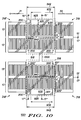
- FIG. 10 illustrates a sixth embodiment (similar to filter 701, FIG. 7) according to the present invention applied to four-pole transversely-coupled filter 1001.
- Filter 1001 includes single electrical coupling track 1000 between transducers 1003, 1005 disposed in second and third tracks 13'. It will be appreciated that ground interconnections 15', 17' between second and third tracks 13' are also required for proper operation of filter 1001.
- first bus bar 940 has first long dimension 942 and first short dimension 941, with the latter preferably having a dimension of less than an acoustic wavelength, while second bus bar 930, disposed parallel to first long dimension 942, has second long dimension 932 and second short dimension 931, with second short dimension 931 exceeding an acoustic wavelength.
- first short dimension 941 was chosen to be 0.207 wavelength wide and separated from neighboring structures by gaps of 0.162 wavelength. This filter provided an insertion loss of about six dB at a frequency of 400 MHz, without a tuning inductor, and provided an insertion loss of 4-5 dB with an inductor.
- gaps 200, 200' of different sizes are often useful because these gaps dictate placement of spurious out-of-band responses in frequency.
- the filters of FIGs. 2, 4, 7, 8 and 10 may be made to have the spurious response from one two-pole group coincident in frequency with nulls from the other two-pole group, improving the overall out-of-band rejection of the composite filter.
- SAW filters such as those illustrated in FIGs.
- 1-10 may be constructed on suitably prepared substrates such as quartz (SiO 2 ), lithium niobate (LiNbO 3 ), lithium tantalate (LiTaO 3 ) and lithium tetraborate (Li 2 B 4 O 7 ).
- quartz SiO 2
- LiNbO 3 lithium niobate
- LiTaO 3 lithium tantalate
- Li 2 B 4 O 7 lithium tetraborate
Landscapes
- Physics & Mathematics (AREA)
- Acoustics & Sound (AREA)
- Surface Acoustic Wave Elements And Circuit Networks Thereof (AREA)
Applications Claiming Priority (2)
| Application Number | Priority Date | Filing Date | Title |
|---|---|---|---|
| US08/689,451 US5793266A (en) | 1996-08-12 | 1996-08-12 | Differential input and/or differential output, transversely-coupled surface acoustic wave filter |
| US689451 | 1996-08-12 |
Publications (2)
| Publication Number | Publication Date |
|---|---|
| EP0825713A2 true EP0825713A2 (fr) | 1998-02-25 |
| EP0825713A3 EP0825713A3 (fr) | 1998-09-16 |
Family
ID=24768528
Family Applications (1)
| Application Number | Title | Priority Date | Filing Date |
|---|---|---|---|
| EP97113082A Withdrawn EP0825713A3 (fr) | 1996-08-12 | 1997-07-30 | Filtre couplée transversalement et méthode à ondes acoustiques de surface comportant une entrée différentielle et/ou une sortie différentielle |
Country Status (3)
| Country | Link |
|---|---|
| US (1) | US5793266A (fr) |
| EP (1) | EP0825713A3 (fr) |
| JP (1) | JPH1093388A (fr) |
Families Citing this family (13)
| Publication number | Priority date | Publication date | Assignee | Title |
|---|---|---|---|---|
| FR2739232B1 (fr) * | 1995-09-26 | 1997-10-24 | Thomson Csf | Filtre a ondes acoustiques de surface utilisant le couplage de trois voies acoustiques |
| GB2306821B (en) * | 1995-11-03 | 2000-05-31 | Advanced Saw Prod Sa | Electro-acoustic device |
| US6348845B2 (en) | 1996-05-23 | 2002-02-19 | Matsushita Electric Industrial Co., Ltd. | Surface acoustic wave filter and multistage surface acoustic wave filter |
| US6801100B2 (en) * | 1996-05-23 | 2004-10-05 | Matsushita Electric Industrial Co., Ltd. | Inter-digital transducer, surface acoustic wave filter and communication apparatus using the same |
| EP0921636B1 (fr) * | 1996-05-23 | 2007-04-04 | Matsushita Electric Industrial Co., Ltd. | Filtre à ondes acoustiques de surface et filtre à ondes acoustiques de surface à plusieurs étages |
| JP3239064B2 (ja) * | 1996-05-28 | 2001-12-17 | 富士通株式会社 | 弾性表面波装置 |
| FR2762458B1 (fr) * | 1997-04-18 | 1999-07-09 | Thomson Csf | Dispositif a ondes acoustiques de surface a couplage par proximite a entrees/sorties differentielles |
| JP3253568B2 (ja) * | 1997-08-29 | 2002-02-04 | 富士通株式会社 | 多段接続型弾性表面波フィルタ |
| JPH11340774A (ja) * | 1998-05-26 | 1999-12-10 | Murata Mfg Co Ltd | 弾性表面波フィルタ |
| JP2000244275A (ja) * | 1999-02-19 | 2000-09-08 | Murata Mfg Co Ltd | Saw共振子フィルタ |
| JP3391346B2 (ja) | 2000-04-18 | 2003-03-31 | 株式会社村田製作所 | 縦結合共振子型弾性表面波フィルタ |
| JP3402311B2 (ja) * | 2000-05-19 | 2003-05-06 | 株式会社村田製作所 | 弾性表面波装置 |
| JP4411539B2 (ja) * | 2005-08-25 | 2010-02-10 | セイコーエプソン株式会社 | Saw共振子 |
Citations (5)
| Publication number | Priority date | Publication date | Assignee | Title |
|---|---|---|---|---|
| JPH05183372A (ja) * | 1991-12-26 | 1993-07-23 | Toshiba Corp | 弾性表面波装置 |
| EP0576340A1 (fr) * | 1992-06-26 | 1993-12-29 | Thomson-Csf | Filtre à ondes de surface à réseaux réfléchissants |
| EP0600705A1 (fr) * | 1992-12-01 | 1994-06-08 | Japan Radio Co., Ltd | Filtre à ondes acoustique de surface et système de communication mobile utilisant ce filtre |
| US5365138A (en) * | 1993-12-02 | 1994-11-15 | Northern Telecom Limited | Double mode surface wave resonators |
| EP0648015A2 (fr) * | 1993-10-08 | 1995-04-12 | Matsushita Electric Industrial Co., Ltd. | Filtre à ondes acoustiques de surface |
Family Cites Families (7)
| Publication number | Priority date | Publication date | Assignee | Title |
|---|---|---|---|---|
| JPS59131213A (ja) * | 1982-07-26 | 1984-07-28 | Toyo Commun Equip Co Ltd | 高周波狭帯域多重モ−ド・フイルタ |
| FR2658013B1 (fr) * | 1990-02-02 | 1992-04-17 | Thomson Csf | Filtre a ondes acoustiques de surface. |
| FR2661292B1 (fr) * | 1990-04-24 | 1995-07-21 | Thomson Csf | Filtre a ondes de surface et a faibles pertes. |
| US5265267A (en) * | 1991-08-29 | 1993-11-23 | Motorola, Inc. | Integrated circuit including a surface acoustic wave transformer and a balanced mixer |
| FR2682833B1 (fr) * | 1991-10-18 | 1993-12-03 | Thomson Csf | Filtre a ondes de surface et a trajet acoustique replie. |
| JP3369581B2 (ja) * | 1991-11-01 | 2003-01-20 | 株式会社東芝 | 多段接続多重モードフィルタ及び弾性表面波フィルタ装置 |
| JP3244386B2 (ja) * | 1994-08-23 | 2002-01-07 | 松下電器産業株式会社 | 弾性表面波装置 |
-
1996
- 1996-08-12 US US08/689,451 patent/US5793266A/en not_active Expired - Fee Related
-
1997
- 1997-06-13 JP JP9173175A patent/JPH1093388A/ja active Pending
- 1997-07-30 EP EP97113082A patent/EP0825713A3/fr not_active Withdrawn
Patent Citations (5)
| Publication number | Priority date | Publication date | Assignee | Title |
|---|---|---|---|---|
| JPH05183372A (ja) * | 1991-12-26 | 1993-07-23 | Toshiba Corp | 弾性表面波装置 |
| EP0576340A1 (fr) * | 1992-06-26 | 1993-12-29 | Thomson-Csf | Filtre à ondes de surface à réseaux réfléchissants |
| EP0600705A1 (fr) * | 1992-12-01 | 1994-06-08 | Japan Radio Co., Ltd | Filtre à ondes acoustique de surface et système de communication mobile utilisant ce filtre |
| EP0648015A2 (fr) * | 1993-10-08 | 1995-04-12 | Matsushita Electric Industrial Co., Ltd. | Filtre à ondes acoustiques de surface |
| US5365138A (en) * | 1993-12-02 | 1994-11-15 | Northern Telecom Limited | Double mode surface wave resonators |
Non-Patent Citations (2)
| Title |
|---|
| PATENT ABSTRACTS OF JAPAN vol. 017, no. 599 (E-1455), 2 November 1993 & JP 05 183372 A (TOSHIBA CORP;OTHERS: 01), 23 July 1993, * |
| SHARIF M A ET AL: "Coupled resonator filters with differential input and/or differential output" 1995 IEEE ULTRASONICS SYMPOSIUM. PROCEEDINGS. AN INTERNATIONAL SYMPOSIUM (CAT. NO.95CH35844), 1995 IEEE ULTRASONICS SYMPOSIUM. PROCEEDINGS. AN INTERNATIONAL SYMPOSIUM, SEATTLE, WA, USA, 7-10 NOV. 1995, ISBN 0-7803-2940-6, 1995, NEW YORK, NY, USA, IEEE, USA, pages 67-70 vol.1, XP002072572 * |
Also Published As
| Publication number | Publication date |
|---|---|
| US5793266A (en) | 1998-08-11 |
| EP0825713A3 (fr) | 1998-09-16 |
| JPH1093388A (ja) | 1998-04-10 |
Similar Documents
| Publication | Publication Date | Title |
|---|---|---|
| US7902940B2 (en) | Duplexer | |
| JP4222197B2 (ja) | 弾性表面波フィルタ、通信機 | |
| EP0652637B1 (fr) | Filtre à ondes acoustiques de surface | |
| EP0718970B1 (fr) | Filtre à ondes acoustiques de surface | |
| EP0772293B1 (fr) | Dispositif électro-acoustique | |
| CN1574620B (zh) | 表面声波滤波器和包括该表面声波滤波器的双工器 | |
| US9847770B2 (en) | Elastic wave resonator, elastic wave filter apparatus, and duplexer | |
| KR100290803B1 (ko) | 탄성표면파장치 | |
| US5793266A (en) | Differential input and/or differential output, transversely-coupled surface acoustic wave filter | |
| US7843285B2 (en) | Piezoelectric thin-film filter | |
| US7868716B2 (en) | Acoustic wave filter apparatus | |
| US6472959B1 (en) | Longitudinally coupled double mode resonator filters using shallow bulk acoustic waves | |
| US7429905B2 (en) | Balanced acoustic wave filter | |
| JP2004523176A (ja) | 表面音響波フィルタ | |
| US6801100B2 (en) | Inter-digital transducer, surface acoustic wave filter and communication apparatus using the same | |
| JP2008516488A (ja) | インピーダンス変換部を備えたsawフィルタ | |
| JP4480490B2 (ja) | 弾性表面波装置およびそれを用いた通信装置 | |
| JP3757893B2 (ja) | 弾性表面波装置、および、これを搭載した通信装置 | |
| JP3366477B2 (ja) | 縦型複合4重モードsawフィルタ | |
| JPH08298432A (ja) | 弾性表面波装置及びそれを用いたアンテナ分波器 | |
| EP0760556A1 (fr) | Filtre à ondes acoustiques avec élément déterminant les caractéristiques de filtrage et procédé | |
| JPH11239035A (ja) | Sawフィルタ | |
| JP3214226B2 (ja) | 弾性表面波共振子フィルタ | |
| JP2001024471A (ja) | 弾性表面波共振子および弾性表面波フィルタ | |
| JP2000349589A (ja) | 弾性表面波フィルタ |
Legal Events
| Date | Code | Title | Description |
|---|---|---|---|
| PUAI | Public reference made under article 153(3) epc to a published international application that has entered the european phase |
Free format text: ORIGINAL CODE: 0009012 |
|
| AK | Designated contracting states |
Kind code of ref document: A2 Designated state(s): DE DK FI FR GB |
|
| PUAL | Search report despatched |
Free format text: ORIGINAL CODE: 0009013 |
|
| AK | Designated contracting states |
Kind code of ref document: A3 Designated state(s): AT BE CH DE DK ES FI FR GB GR IE IT LI LU MC NL PT SE |
|
| 17P | Request for examination filed |
Effective date: 19990316 |
|
| AKX | Designation fees paid |
Free format text: DE DK FI FR GB |
|
| RBV | Designated contracting states (corrected) |
Designated state(s): DE DK FI FR GB |
|
| RAP1 | Party data changed (applicant data changed or rights of an application transferred) |
Owner name: CTS CORPORATION |
|
| STAA | Information on the status of an ep patent application or granted ep patent |
Free format text: STATUS: THE APPLICATION IS DEEMED TO BE WITHDRAWN |
|
| 18D | Application deemed to be withdrawn |
Effective date: 20020201 |