EP0824010B2 - Embolisationsspirale - Google Patents
Embolisationsspirale Download PDFInfo
- Publication number
- EP0824010B2 EP0824010B2 EP97113673A EP97113673A EP0824010B2 EP 0824010 B2 EP0824010 B2 EP 0824010B2 EP 97113673 A EP97113673 A EP 97113673A EP 97113673 A EP97113673 A EP 97113673A EP 0824010 B2 EP0824010 B2 EP 0824010B2
- Authority
- EP
- European Patent Office
- Prior art keywords
- coiled
- embolizing material
- coiled body
- push
- end portion
- Prior art date
- Legal status (The legal status is an assumption and is not a legal conclusion. Google has not performed a legal analysis and makes no representation as to the accuracy of the status listed.)
- Expired - Lifetime
Links
- 239000000463 material Substances 0.000 title claims description 69
- 229920001577 copolymer Polymers 0.000 claims description 5
- 229920002451 polyvinyl alcohol Polymers 0.000 claims description 4
- 210000005166 vasculature Anatomy 0.000 claims description 3
- 210000003092 coiled body Anatomy 0.000 description 67
- 206010002329 Aneurysm Diseases 0.000 description 27
- 210000004204 blood vessel Anatomy 0.000 description 11
- 239000011347 resin Substances 0.000 description 8
- 229920005989 resin Polymers 0.000 description 8
- 230000002093 peripheral effect Effects 0.000 description 5
- 238000004804 winding Methods 0.000 description 5
- 208000007536 Thrombosis Diseases 0.000 description 4
- BASFCYQUMIYNBI-UHFFFAOYSA-N platinum Chemical compound [Pt] BASFCYQUMIYNBI-UHFFFAOYSA-N 0.000 description 4
- 239000000853 adhesive Substances 0.000 description 3
- 230000001070 adhesive effect Effects 0.000 description 3
- 239000011247 coating layer Substances 0.000 description 3
- 238000010276 construction Methods 0.000 description 3
- 238000010438 heat treatment Methods 0.000 description 3
- -1 poly(vinyl alcohol) Polymers 0.000 description 3
- 230000010102 embolization Effects 0.000 description 2
- NBVXSUQYWXRMNV-UHFFFAOYSA-N fluoromethane Chemical compound FC NBVXSUQYWXRMNV-UHFFFAOYSA-N 0.000 description 2
- 238000002594 fluoroscopy Methods 0.000 description 2
- 238000002844 melting Methods 0.000 description 2
- 230000008018 melting Effects 0.000 description 2
- 229910052697 platinum Inorganic materials 0.000 description 2
- 239000010935 stainless steel Substances 0.000 description 2
- 229910001220 stainless steel Inorganic materials 0.000 description 2
- WFKWXMTUELFFGS-UHFFFAOYSA-N tungsten Chemical compound [W] WFKWXMTUELFFGS-UHFFFAOYSA-N 0.000 description 2
- 229910052721 tungsten Inorganic materials 0.000 description 2
- 239000010937 tungsten Substances 0.000 description 2
- 230000002792 vascular Effects 0.000 description 2
- 201000008450 Intracranial aneurysm Diseases 0.000 description 1
- 229910001260 Pt alloy Inorganic materials 0.000 description 1
- BQCADISMDOOEFD-UHFFFAOYSA-N Silver Chemical compound [Ag] BQCADISMDOOEFD-UHFFFAOYSA-N 0.000 description 1
- 230000002411 adverse Effects 0.000 description 1
- 229910045601 alloy Inorganic materials 0.000 description 1
- 239000000956 alloy Substances 0.000 description 1
- 230000015572 biosynthetic process Effects 0.000 description 1
- 239000008280 blood Substances 0.000 description 1
- 210000004369 blood Anatomy 0.000 description 1
- 239000011248 coating agent Substances 0.000 description 1
- 238000000576 coating method Methods 0.000 description 1
- 239000004020 conductor Substances 0.000 description 1
- 238000000151 deposition Methods 0.000 description 1
- 238000005868 electrolysis reaction Methods 0.000 description 1
- PCHJSUWPFVWCPO-UHFFFAOYSA-N gold Chemical compound [Au] PCHJSUWPFVWCPO-UHFFFAOYSA-N 0.000 description 1
- 229910052737 gold Inorganic materials 0.000 description 1
- 239000010931 gold Substances 0.000 description 1
- 238000003780 insertion Methods 0.000 description 1
- 230000037431 insertion Effects 0.000 description 1
- 230000009545 invasion Effects 0.000 description 1
- 229910052751 metal Inorganic materials 0.000 description 1
- 239000002184 metal Substances 0.000 description 1
- 238000000034 method Methods 0.000 description 1
- 229920000642 polymer Polymers 0.000 description 1
- 229910001285 shape-memory alloy Inorganic materials 0.000 description 1
- 229910052709 silver Inorganic materials 0.000 description 1
- 239000004332 silver Substances 0.000 description 1
- 238000003466 welding Methods 0.000 description 1
Images


Classifications
-
- A—HUMAN NECESSITIES
- A61—MEDICAL OR VETERINARY SCIENCE; HYGIENE
- A61B—DIAGNOSIS; SURGERY; IDENTIFICATION
- A61B17/00—Surgical instruments, devices or methods
- A61B17/12—Surgical instruments, devices or methods for ligaturing or otherwise compressing tubular parts of the body, e.g. blood vessels or umbilical cord
- A61B17/12022—Occluding by internal devices, e.g. balloons or releasable wires
- A61B17/12099—Occluding by internal devices, e.g. balloons or releasable wires characterised by the location of the occluder
- A61B17/12109—Occluding by internal devices, e.g. balloons or releasable wires characterised by the location of the occluder in a blood vessel
- A61B17/12113—Occluding by internal devices, e.g. balloons or releasable wires characterised by the location of the occluder in a blood vessel within an aneurysm
-
- A—HUMAN NECESSITIES
- A61—MEDICAL OR VETERINARY SCIENCE; HYGIENE
- A61B—DIAGNOSIS; SURGERY; IDENTIFICATION
- A61B17/00—Surgical instruments, devices or methods
- A61B17/12—Surgical instruments, devices or methods for ligaturing or otherwise compressing tubular parts of the body, e.g. blood vessels or umbilical cord
- A61B17/12022—Occluding by internal devices, e.g. balloons or releasable wires
- A61B17/12131—Occluding by internal devices, e.g. balloons or releasable wires characterised by the type of occluding device
- A61B17/1214—Coils or wires
- A61B17/12145—Coils or wires having a pre-set deployed three-dimensional shape
-
- A—HUMAN NECESSITIES
- A61—MEDICAL OR VETERINARY SCIENCE; HYGIENE
- A61B—DIAGNOSIS; SURGERY; IDENTIFICATION
- A61B17/00—Surgical instruments, devices or methods
- A61B17/12—Surgical instruments, devices or methods for ligaturing or otherwise compressing tubular parts of the body, e.g. blood vessels or umbilical cord
- A61B17/12022—Occluding by internal devices, e.g. balloons or releasable wires
- A61B2017/1205—Introduction devices
- A61B2017/12054—Details concerning the detachment of the occluding device from the introduction device
- A61B2017/12068—Details concerning the detachment of the occluding device from the introduction device detachable by heat
- A61B2017/12077—Joint changing shape upon application of heat, e.g. bi-metal or reversible thermal memory
Definitions
- the present invention relates to a coiled embolizing material to be deposited at an intended site in a vasculature of; for example, a human body.
- vascular embolization As a method for treating an aneurysm or the like, which causes little invasion, attention has been recently attracted to vascular embolization in which an embolizing material is deposited within a dilatation.
- an embolizing material is deposited within a dilatation.
- U.S. Patent Nos. 4,884,579 and 4,739,768 In this vascular embolization, the embolizing material deposited within the aneurysm serves as a physical obstacle to a blood stream and can facilitate the formation of thrombus to reduce the risk of aneurysmal rupture.
- embolizing material As the embolizing material to be deposited at an intended site in the vasculature, coiled embolizing materials have been known.
- Such a coiled embolizing material is introduced into an aneurysm through a suitable catheter by means of a wire-made push-out means or a guide detachably connected to an end thereof.
- a wire-made push-out means or a guide detachably connected to an end thereof Reference may be made to, for example, Japanese Patent Application Laid-Open (KOHYO) Nos. 500322/1993, 501015/1996 and 502674/1995 (through PCT route)
- the coiled embollzing material, to which the push-out means has been connected is inserted into the catheter, which has been inserted into the vital body in advance in such a manner that its distal opening is sited within the aneurysm, with the coiled embolizing material in the lead.
- the embolizing material is transferred through the catheter while being pushed by the push-out means, whereby it is pushed out of the distal opening of the catheter into the dilatation.
- the push-out means is detached from the embolizing material making good use of a mechanical means, electrolysis or the like, whereby only the embolizing material is deposited within the aneurysm.
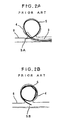
- FIG. 1 illustrates a conventional coiled body making up a coiled embolizing material.
- This coiled body 1 is a helical double-coiled body having deformability.
- a semi-spherical tip 2 is formed at one end thereof.
- the coiled body 1 Since the coiled body 1 has deformability, it shows a state that it is stretched in a substantially straight line along a catheter when it is pushed by a push-out means to move through the catheter, and returns to the original double-coiled body (the shape illustrated in FIG. 1) when it is pushed out of the catheter into an aneurysm, and the push-out means is detached from the coiled body.
- the outer diameter of the coiled body making up the embolizing material (for example, the outer diameter of the double-coiled body illustrated in FIG. 1) must be generally made somewhat greater than the inner diameter (the inner diameter when an internal space of the aneurysm is regarded as a sphere) of the aneurysm in which the coiled body should be deposited.
- a distal end portion 5A of a coiled body 5, which has been pushed out of a distal opening of a catheter 3 into an aneurysm 4, may extend out of the opening of the aneurysm 4 into a parental blood vessel 6 outside the dilatation.
- a proximal end portion 5B of the coiled body 5 deposited within the aneurysm 4 after a push-out means (not illustrated) is detached may extend out of the opening of the aneurysm 4 into the parental blood vessel 6 outside the dilatation.
- Such a state as described above particularly tends to occur when an aneurysm to be embolized has a slender form.
- thrombus is formed on the end portion of the coiled body extended out of the dilatation, and so the parental blood vessel Is occluded by the thrombus, or the thrombus transmigrates to a peripheral vessel, thereby occluding such a peripheral vessel.
- the present invention has been completed under the foregoing circumstances. It is an object of the present invention to provide a coiled embolizing material, which can surely embolize an application site without extending either end portion thereof out into a vessel, for example, a parental blood vessel outside a dilatation, outside the application site.
- a push-out means for the embolizing material may preferably be detachably connected to the embolizing material.
- the push-out means for the embolizing material may preferably be detachably connected to the embolizing material through a joint member.
- the joint member may preferably be formed of poly(vinyl alcohol) or a vinyl alcohol copolymer.
- the coiled embolizing material can be deposited at an application site in a state that it is fitted to the inner wall of the application site, and moreover the end portion of the coiled embolizing material can be prevented from extending out into a vessel outside the application site.
- the coiled embolizing material having the distal end portion curved inward moves along the inner wall of the application site in a state that the distal end thereof points to the interior of the dilatation. Therefore, the distal end portion of the embolizing material pushed out of the distal opening of, for example, a catheter into the aneurysm does not damage the inner wall surface of the aneurysm, and is surely present in the aneurysm, thereby preventing it from extending out of the dilatation into a parental blood vessel.
- the push-out means When the push-out means is detached from the coiled embolizing material introduced into the application site or dilatation, the coiled embolizing material having the proximal end portion curved inward returns to a state that the proximal end thereof points to the interior of the dilatation. Therefore, the proximal end portion of the embolizing material deposited into the aneurysm is surely present in the aneurysm, thereby preventing it from extending out of the dilatation into a parental blood vessel.
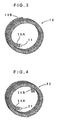
- FIG. 3 illustrates an example of a coiled body making up a coiled embolizing material according to the present invention.
- the coiled body 10 is composed of a helical double-coiled body having deformability and is so constructed that a distal end portion 10A thereof is curved inward in a radial direction of a secondary coil thereof.
- Reference numeral 11 denotes a tip mounted at a distal end of the coiled body 10.
- the tip 11 is formed in a semi-spherical shape having a smooth surface by, for example, melting a wire for the coiled body from the viewpoint of preventing an application site from being damaged.
- the coiled body 10 is preferably formed from a wire capable of observing by X-ray fluoroscopy, such as platinum, gold, tungsten or an alloy thereof.
- a diameter of the wire for forming the coiled body 10 is about 0.02-0.12 mm.
- the coiled body 10 is a helical double-coiled body obtained by winding the above-described wire to form a primary coil and further winding the primary coil to form a secondary coil.
- a diameter of the primary coil is generally 0.1-1.0 mm, preferably 0.2-0.5 mm, while a diameter of the secondary coil is suitably selected according to the inner diameter of an application site, for example, aneurysm, but is generally 2-40 mm, preferably 2-20 mm.
- the coiled body 10 has a feature that the distal end portion 10A thereof is curved inward in the radial direction of th e secondary coil.
- the length of the curved portion or the distal end portion 10A is 0.25L-0.5L wherein L denotes a perimeter of unit coil of the secondary coil. If the length of the curved portion is too short, it is impossible to sufficiently prevent the distal end portion from extending out of the dilatation. On the other hand, if the length of the curved portion is too long, it is impossible to maintain a state that the coiled body has been fitted to the inner wall of the application site.
- the curved portion or the distal end portion 10A of the coiled body 10 may have either the same curvature or an increasing curvature, for example, clothoid, toward the distal end.
- the curvature of the curved portion is preferably greater than that of the inner wall of the application site.
- the distal end portion 10A may be wound at least one tum along a circle of a diameter smaller than that of the secondary coil..
- a push-out means is connected to a proximal end 10B of the coiled body 10, and the coiled body 10 is introduced into the application site through a suitable catheter 3, whereby the distal end portion 10A of the embolizing material 10 pushed out of the distal opening of the catheter 3 into the application site 7 neither sticks in the inner wall surface nor damages it and is surely present within the application site 7, as illustrated in FIG. 5A, and so it is prevented from extending out into a parental blood vessel 6 outside the dilatation.
- FIG. 4 illustrates another example of a coiled body making up a coiled embolizing material according to the present invention.
- the coiled body 20 is composed of a helical double-coiled body having deformability and is so constructed that both distal end portion 20A and proximal end portion 20B thereof are curved inward in a radial direction of a secondary coil thereof.
- Reference numeral 21 denotes a semi-spherical tip mounted or formed at a distal end of the coiled body 20.
- the coiled body 20 has a feature that both distal end portion 20A and proximal end portion 20B thereof are curved inward in the radial direction of a secondary coil thereof. Other constructions thereof are the same as those described in the coiled body 10. Curving conditions such as length and shape for the proximal end portion 20B may also be the same as those for the distal end portions 20A.
- a push-out means is connected to a proximal end of the coiled body 20, and the coiled body 20 is introduced into the application site through a suitable catheter, whereby both distal end portion 20A and proximal end portion 20B of the embolizing material 20 deposited within the application site 7 are surely present within the application site 7, as illustrated in FIG. 5B, and so they are prevented from extending out into a parental blood vessel 6 outside the dilatation.
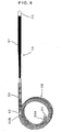
- FIG. 6 illustrates a further example of a coiled body making up a coiled embolizing material according to the present invention.
- a push-out means 50 for the embolizing material is connected to a proximal end of the coiled body 30 through a rod-like joint member 40.
- Reference numeral 31 denotes a semi-spherical tip mounted or formed at a distal end of the coiled body 30.
- the coiled body 30 has the same construction as the coiled body 20 according to the second embodiment, and so the proximal end portion 30B thereof is recovered so as to curve inward in a radial direction of a secondary coil thereof when the push-out means 50 is detached.
- the push-out means 50 is a guide or coil pusher for introducing the coiled body 30 making up the embolizing material into an application site.
- the push-out means 50 includes a wire part 51 obtained by forming a coating layer of resin on a peripheral surface of a core wire and a distal X-ray impervious part 52 contiguous to the wire part.
- the push-out means 50 has an outer diameter of, for example, 0.1 to 2.0 mm and a length of, for example, 0.1-2.0 m.
- As the core wire making up the push-out means 50 there may be used a wire formed of a conductive material such as a stainless steel.
- the coating layer of resin in the wire part 51 of the push-out means 50 can be formed by coating the peripheral surface of the core wire with, for example, a fluorocarbon resin or hydrophilic resin.
- the coating layer of resin formed of the fluorocarbon resin or hydrophilic resin is preferred in that the coefficient of friction of the surface can be made low.
- the core wire is exposed to form a terminal part 53 through which electric powercan be supplied via suitable conductive members such as an electrical connector, plug and/or clip. About 1 to 3 cm suffice the length of this terminal part 53.
- the distal X-ray impervious part 52 of the push-out means 50 is constructed by further closely winding a winding wire in the form of a coil on the peripheral surface of the core wire.
- a winding wire in the form of a coil on the peripheral surface of the core wire.
- the winding wire making up the distal X-ray impervious part 52 there may be used a wire formed of a metal such as platinum, silver or tungsten.
- the distal X-ray impervious part 52 of the push-out means 50 is connected and fixed to the proximal end of the coiled body 30 through the joint member 40.
- No particular limitation is imposed on the means for fixing the proximal end of the coiled body 30 to the joint member 40, and the means for fixing the distal X-ray impervious part 52 of the push-out means to the joint member 40.
- bonding with an adhesive, welding, connection by physical force or the like may be used.
- a material for the joint member 40 interposing between the coiled body 30 and the push-out means 50 may be any material so far as it does not adversely affect the vital body and can be melted and severed by heating. More specifically, poly(vinyl alcohol) or a vinyl alcohol copolymer, which is melted by heating, is preferred. However, the material for the joint member 40 is not limited to these polymers. For example, a material, which is deformed by heating, such as a shape-memory alloy or resin, may be used.
- the coiled body 30 to which the push-out means 50 has been connected through the joint member 40 is introduced into an application site within the vital body via a suitable catheter.
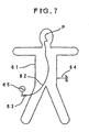
- the coiled body for example, the coiled body 30 illustrated in FIG. 6, to which the push-out means has been connected, is inserted into a catheter 62, which has been inserted in advance in such a manner that the distal opening thereof reaches an application site P in the vital body 61, through a proximal operating part 63 of the catheter 62 with the coiled body in the lead.
- the coiled body is transferred through the catheter 62 by being pushed by the push-out means in a state that the coil has been forcedly stretched in a substantially straight line along the catheter 62, whereby the coiled body is pushed out of the distal opening of the catheter 62 into the application site P.
- an earth electrode 64 is attached to the skin surface of the vital body 61, and a high-frequency power source 65 is connected to the terminal part of the push-out means to supply, for example, a monopolar high-frequency current to the push-out means.
- the joint member 40 interposing between the coiled body 30 and the push-out means 50 generates heat by the high-frequency current, and so the joint member 40 is melted and severed. Therefore, the coiled body 30 is separated from the push-out means 50, whereby an embolizing material composed of the coiled body 30 can be deposited within the application site. Since both distal end portion 30A and proximal end portion 30B of the coiled body 30 thus deposited are curved inward in the radial direction of the secondary coil thereof, they are prevented from extending out into a parental blood vessel outside a dilatation at the application site.
- the joint member 40 when a material having sufficiently high stiffness and mechanical strength at the temperature of the human body, and a melting point of 100 °C or lower is selected as a material for the joint member 40, the joint member 40 can be heated and severed within a short period of time by supplying the high-frequency current thereto. More specifically, when the joint member 40 is formed of poly(vinyl alcohol) or a vinyl alcohol copolymer, the joint member 40 can be melted and severed by supplying a high-frequency current for an extremely short period within 3 seconds, for example. Therefore, burdens imposed not only on a surgeon, but also on a patient to be operated can be very lightened. In addition, a possibility that contingencies-may occur on the vital body during the depositing operation can be lessened to a great extent.
- a proximal end of a joint member 40 formed of an uncrosslinked vinyl alcohol copolymer in the form of a columnar rod having a diameter of 0.2 mm and a length of 10 mm was bonded with an adhesive to a distal end of a push-out means 50 made of stainless steel having an outer diameter of 0.4 mm and an overall length of 1,800 mm and having a distal X-ray impervious part 52 of 30 mm in length.
- a proximal end of a coiled body 30 was bonded to a distal end of the joint member 40 with an adhesive, thereby producing an embolizing material-introducing device having a coiled embolizing material or coiled body 30 according to the present invention.
- the coiled body 30 used was composed of a double-coiled body having a primary coil diameter of 0.4 mm and a secondary coil diameter of 14 mm, constructed by a platinum alloy wire having a diameter of 0.08 mm in such a manner that the distal end portion 30A of 10 mm and the proximal end portion 308 of 10 mm thereof were curved inward in a radial direction of the secondary coil thereof.
- the diameter of the curved portion was 10 mm in length.
- the embolizing material-introducing device thus produced was inserted into a microcatheter 33, which had been inserted in advance so as to site the distal opening thereof at a human cerebral aneurysm, which was a substantially spherical dilatation having an inner diameter of about 13-14 mm, with the coiled body in the lead.
- an earth electrode was attached to the skin surface of the human body, and a high-frequency power source was connected to a terminal part of the push-out means to supply a high-frequency current of a frequency of 300 kHz and electric power of about 5-6 W to the push-out means.
- the joint member was instantaneously melted and severed to detach the coiled body from the push-out means, thereby completing the introduction of the coiled body which was the embolizing material according to the present invention.
- the coiled body was observed by X-ray fluoroscopy, it was found that the coiled body returned to the original shape and was deposited within the aneurysm in a state that it was fitted to the inner wall of the aneurysm, and that both distal end and proximal end portions of the coiled body were present within the dilatation and did not extend out of the dilatation.
- the coiled embolizing material according to the present invention is deposited in an application site so as to fit it to the inner wall thereof, thereby ensuring that the application site can be embolized. In addition, either end portion thereof is prevented from extending out into a vessel outside the application site, for example, a parental blood vessel outside the dilatation.
- the site or dilatation which can be embolized by the coiled embolizing material according to the present invention is not limited to the spherical dilatation.
- the coiled embolizing material of the present invention for example, such a slender dilatation that when the conventional helical coiled body is introduced therein, an end portion thereof extends out of the dilatation, can also be embolized without extending either end portion thereof out of the dilatation.
Landscapes
- Health & Medical Sciences (AREA)
- Surgery (AREA)
- Life Sciences & Earth Sciences (AREA)
- Heart & Thoracic Surgery (AREA)
- Molecular Biology (AREA)
- Vascular Medicine (AREA)
- Engineering & Computer Science (AREA)
- Biomedical Technology (AREA)
- Reproductive Health (AREA)
- Medical Informatics (AREA)
- Nuclear Medicine, Radiotherapy & Molecular Imaging (AREA)
- Animal Behavior & Ethology (AREA)
- General Health & Medical Sciences (AREA)
- Public Health (AREA)
- Veterinary Medicine (AREA)
- Neurosurgery (AREA)
- Surgical Instruments (AREA)
- Media Introduction/Drainage Providing Device (AREA)
Claims (4)
- Gewickeltes Embolisationsmaterial zur Unterbringung an einer gewünschten Stelle in einer Gefäßanordnung, wobei das gewickelte Embolisationsmaterial einen doppelt gewickelten Körper umfaßt, wobei wenigstens ein Endabschnitt (10A, 20A, 20B, 30A) des doppelt-gewickelten Körpers nach innen in einer radialen Richtung einer sekundären Wicklung davon gekrümmt ist, und wobei der wenigstens eine Endabschnitt eine Länge in dem Bereich 0,25 L - 0,5 L hat, wobei L einen Umfang einer Einzeiwicklung der sekundären Spule bezeichnet.
- Gewickeltes Embolisationsmaterial gemäß Anspruch 1, wobei eine Ausschiebevorrichtung (50) für das Embolisationsmaterial lösbar mit dem Embolisationsmaterial verbunden ist.
- Gewickeltes Embolisationsmaterial gemäß Anspruch 2, wobei die Ausschiebevorrichtung (50) für das Embolisationsmaterial lösbar mit dem Embolisationsmaterial durch ein Verbindungselement (40) verbunden ist.
- Gewickeltes Embolisationsmaterial gemäß Anspruch 3, wobei das Verbindungselement (40) aus Poly(Vinylalkohol) oder einem Vinylalkoholcopolymer besteht.
Applications Claiming Priority (3)
| Application Number | Priority Date | Filing Date | Title |
|---|---|---|---|
| JP21555396 | 1996-08-15 | ||
| JP21555396A JP3784112B2 (ja) | 1996-08-15 | 1996-08-15 | コイル状塞栓物質 |
| JP215553/96 | 1996-08-15 |
Publications (4)
| Publication Number | Publication Date |
|---|---|
| EP0824010A2 EP0824010A2 (de) | 1998-02-18 |
| EP0824010A3 EP0824010A3 (de) | 1998-02-25 |
| EP0824010B1 EP0824010B1 (de) | 2003-02-26 |
| EP0824010B2 true EP0824010B2 (de) | 2006-01-11 |
Family
ID=16674341
Family Applications (1)
| Application Number | Title | Priority Date | Filing Date |
|---|---|---|---|
| EP97113673A Expired - Lifetime EP0824010B2 (de) | 1996-08-15 | 1997-08-07 | Embolisationsspirale |
Country Status (4)
| Country | Link |
|---|---|
| US (1) | US5891058A (de) |
| EP (1) | EP0824010B2 (de) |
| JP (1) | JP3784112B2 (de) |
| DE (1) | DE69719257T3 (de) |
Families Citing this family (33)
| Publication number | Priority date | Publication date | Assignee | Title |
|---|---|---|---|---|
| US6984240B1 (en) | 1996-10-25 | 2006-01-10 | Target Therapeutics, Inc. | Detachable multidiameter vasoocclusive coil |
| US6136015A (en) * | 1998-08-25 | 2000-10-24 | Micrus Corporation | Vasoocclusive coil |
| US6113629A (en) * | 1998-05-01 | 2000-09-05 | Micrus Corporation | Hydrogel for the therapeutic treatment of aneurysms |
| EP1200012B1 (de) * | 1999-06-02 | 2007-11-07 | Sethel Interventional, Inc. | Intrakorporale verschlussvorrichtung |
| US6355275B1 (en) | 2000-06-23 | 2002-03-12 | Carbon Medical Technologies, Inc. | Embolization using carbon coated microparticles |
| US6394965B1 (en) | 2000-08-15 | 2002-05-28 | Carbon Medical Technologies, Inc. | Tissue marking using biocompatible microparticles |
| US7029486B2 (en) * | 2000-09-26 | 2006-04-18 | Microvention, Inc. | Microcoil vaso-occlusive device with multi-axis secondary configuration |
| US7033374B2 (en) | 2000-09-26 | 2006-04-25 | Microvention, Inc. | Microcoil vaso-occlusive device with multi-axis secondary configuration |
| US6605101B1 (en) | 2000-09-26 | 2003-08-12 | Microvention, Inc. | Microcoil vaso-occlusive device with multi-axis secondary configuration |
| US20020165582A1 (en) * | 2001-04-26 | 2002-11-07 | Porter Christopher H. | Method and apparatus for delivering materials to the body |
| EP2163212B1 (de) | 2001-11-07 | 2015-09-23 | Microvention, Inc. | Gefäßverschließende Mikrospiraleinrichtung mit multi-axialer Sekundäranordnung |
| US8845676B2 (en) | 2004-09-22 | 2014-09-30 | Micro Therapeutics | Micro-spiral implantation device |
| DE502004008712D1 (de) | 2004-09-22 | 2009-01-29 | Dendron Gmbh | Medizinisches implantat |
| US9055948B2 (en) * | 2004-11-09 | 2015-06-16 | Stryker Corporation | Vaso-occlusive devices comprising complex-shape proximal portion and smaller diameter distal portion |
| US8777979B2 (en) | 2006-04-17 | 2014-07-15 | Covidien Lp | System and method for mechanically positioning intravascular implants |
| ES2564780T3 (es) | 2006-04-17 | 2016-03-29 | Covidien Lp | Sistema para colocar mecánicamente implantes intravasculares |
| CA2680793C (en) | 2007-03-13 | 2015-07-07 | Microtherapeutics, Inc. | An implant, a mandrel, and a method of forming an implant |
| US8328860B2 (en) | 2007-03-13 | 2012-12-11 | Covidien Lp | Implant including a coil and a stretch-resistant member |
| WO2009082716A1 (en) | 2007-12-21 | 2009-07-02 | Microvention, Inc. | System and method for locating detachment zone of a detachable implant |
| CN102036619B (zh) | 2007-12-21 | 2014-07-23 | 微排放器公司 | 检测植入物的脱卸的系统 |
| US8333796B2 (en) * | 2008-07-15 | 2012-12-18 | Penumbra, Inc. | Embolic coil implant system and implantation method |
| US20120071911A1 (en) * | 2009-05-20 | 2012-03-22 | University Of Miami | Spherical helix embolic coils for the treatment of cerebral aneurysms |
| WO2011038017A1 (en) | 2009-09-22 | 2011-03-31 | Penumbra, Inc. | Manual actuation system for deployment of implant |
| CN103037776B (zh) | 2010-04-14 | 2017-07-04 | 微排放器公司 | 植入物输送装置 |
| US9579104B2 (en) | 2011-11-30 | 2017-02-28 | Covidien Lp | Positioning and detaching implants |
| US9011480B2 (en) | 2012-01-20 | 2015-04-21 | Covidien Lp | Aneurysm treatment coils |
| US9687245B2 (en) | 2012-03-23 | 2017-06-27 | Covidien Lp | Occlusive devices and methods of use |
| JP5986320B2 (ja) * | 2012-10-19 | 2016-09-06 | クック・メディカル・テクノロジーズ・リミテッド・ライアビリティ・カンパニーCook Medical Technologies Llc | 自己巻取り式スタイレット針デバイス |
| EP3110343B1 (de) | 2014-02-27 | 2018-10-31 | Incumedx Inc. | Embolische rahmungsmikrospulen |
| US9713475B2 (en) | 2014-04-18 | 2017-07-25 | Covidien Lp | Embolic medical devices |
| US10307168B2 (en) | 2015-08-07 | 2019-06-04 | Terumo Corporation | Complex coil and manufacturing techniques |
| WO2019164877A1 (en) | 2018-02-20 | 2019-08-29 | Boston Scientific Scimed, Inc. | Medical device release system |
| US12114863B2 (en) | 2018-12-05 | 2024-10-15 | Microvention, Inc. | Implant delivery system |
Family Cites Families (20)
| Publication number | Priority date | Publication date | Assignee | Title |
|---|---|---|---|---|
| DD158084A1 (de) * | 1981-05-08 | 1982-12-29 | Joachim Heinke | Verschlusskoerper und verfahren zu seiner herstellung |
| US4676249A (en) * | 1986-05-19 | 1987-06-30 | Cordis Corporation | Multi-mode guidewire |
| US4739768B2 (en) * | 1986-06-02 | 1995-10-24 | Target Therapeutics Inc | Catheter for guide-wire tracking |
| US4884579A (en) * | 1988-04-18 | 1989-12-05 | Target Therapeutics | Catheter guide wire |
| US4994069A (en) * | 1988-11-02 | 1991-02-19 | Target Therapeutics | Vaso-occlusion coil and method |
| US5122136A (en) * | 1990-03-13 | 1992-06-16 | The Regents Of The University Of California | Endovascular electrolytically detachable guidewire tip for the electroformation of thrombus in arteries, veins, aneurysms, vascular malformations and arteriovenous fistulas |
| US5354295A (en) * | 1990-03-13 | 1994-10-11 | Target Therapeutics, Inc. | In an endovascular electrolytically detachable wire and tip for the formation of thrombus in arteries, veins, aneurysms, vascular malformations and arteriovenous fistulas |
| US5217484A (en) * | 1991-06-07 | 1993-06-08 | Marks Michael P | Retractable-wire catheter device and method |
| US5261916A (en) * | 1991-12-12 | 1993-11-16 | Target Therapeutics | Detachable pusher-vasoocclusive coil assembly with interlocking ball and keyway coupling |
| US5258042A (en) * | 1991-12-16 | 1993-11-02 | Henry Ford Health System | Intravascular hydrogel implant |
| IL106946A0 (en) * | 1992-09-22 | 1993-12-28 | Target Therapeutics Inc | Detachable embolic coil assembly |
| JPH06246004A (ja) * | 1993-02-26 | 1994-09-06 | Raifu Technol Kenkyusho | カテーテル |
| EP0746375B1 (de) * | 1993-10-22 | 2005-02-02 | SciMed Life Systems, Inc. | Stentzuführvorrichtung und -verfahren |
| US5423829A (en) * | 1993-11-03 | 1995-06-13 | Target Therapeutics, Inc. | Electrolytically severable joint for endovascular embolic devices |
| JP2880070B2 (ja) * | 1994-03-31 | 1999-04-05 | 株式会社カネカメディックス | 生体内留置部材を有する医療用ワイヤー |
| JPH07284534A (ja) * | 1994-04-15 | 1995-10-31 | Kato Hatsujo Kaisha Ltd | 管状器官の治療具 |
| IL116561A0 (en) * | 1994-12-30 | 1996-03-31 | Target Therapeutics Inc | Severable joint for detachable devices placed within the body |
| US5639277A (en) * | 1995-04-28 | 1997-06-17 | Target Therapeutics, Inc. | Embolic coils with offset helical and twisted helical shapes |
| NO962336L (no) * | 1995-06-06 | 1996-12-09 | Target Therapeutics Inc | Vaso-okklusiv spiral |
| US5649949A (en) * | 1996-03-14 | 1997-07-22 | Target Therapeutics, Inc. | Variable cross-section conical vasoocclusive coils |
-
1996
- 1996-08-15 JP JP21555396A patent/JP3784112B2/ja not_active Expired - Lifetime
-
1997
- 1997-08-06 US US08/907,236 patent/US5891058A/en not_active Expired - Lifetime
- 1997-08-07 EP EP97113673A patent/EP0824010B2/de not_active Expired - Lifetime
- 1997-08-07 DE DE69719257T patent/DE69719257T3/de not_active Expired - Lifetime
Also Published As
| Publication number | Publication date |
|---|---|
| EP0824010B1 (de) | 2003-02-26 |
| EP0824010A2 (de) | 1998-02-18 |
| JP3784112B2 (ja) | 2006-06-07 |
| JPH1057385A (ja) | 1998-03-03 |
| DE69719257D1 (de) | 2003-04-03 |
| US5891058A (en) | 1999-04-06 |
| DE69719257T2 (de) | 2003-09-18 |
| EP0824010A3 (de) | 1998-02-25 |
| DE69719257T3 (de) | 2006-11-02 |
Similar Documents
| Publication | Publication Date | Title |
|---|---|---|
| EP0824010B2 (de) | Embolisationsspirale | |
| US6743251B1 (en) | Implantable devices with polymeric detachment junction | |
| US6533801B2 (en) | Vaso-occlusive member assembly with multiple detaching points | |
| JP3557386B2 (ja) | 導電性体液内で体腔を閉塞するための電解分離可能なワイヤ先端部分 | |
| EP0715502B1 (de) | Elektrolytisch trennbare spirale mit beweglichem ablösepunkt | |
| EP1255493B1 (de) | Intraluminales verabreichungssystem | |
| JP4106178B2 (ja) | 迅速取り外し電気絶縁インプラント | |
| US5759161A (en) | Medical wire and method for leaving implanted devices | |
| EP0996372B1 (de) | Mit schmelzklebstoffverbindung versehene, abtrennbare, gefässverschliessende vorrichtung | |
| US5891128A (en) | Solderless electrolytically severable joint for detachable devices placed within the mammalian body | |
| US20020091380A1 (en) | Assembly containing an electrolytically severable joint for endovascular embolic devices |
Legal Events
| Date | Code | Title | Description |
|---|---|---|---|
| PUAI | Public reference made under article 153(3) epc to a published international application that has entered the european phase |
Free format text: ORIGINAL CODE: 0009012 |
|
| PUAL | Search report despatched |
Free format text: ORIGINAL CODE: 0009013 |
|
| AK | Designated contracting states |
Kind code of ref document: A2 Designated state(s): DE FR GB |
|
| AK | Designated contracting states |
Kind code of ref document: A3 Designated state(s): AT BE CH DE DK ES FI FR GB GR IE IT LI LU MC NL PT SE |
|
| 17P | Request for examination filed |
Effective date: 19980529 |
|
| AKX | Designation fees paid |
Free format text: DE FR GB |
|
| RBV | Designated contracting states (corrected) |
Designated state(s): DE FR GB |
|
| GRAG | Despatch of communication of intention to grant |
Free format text: ORIGINAL CODE: EPIDOS AGRA |
|
| 17Q | First examination report despatched |
Effective date: 20020422 |
|
| GRAG | Despatch of communication of intention to grant |
Free format text: ORIGINAL CODE: EPIDOS AGRA |
|
| GRAH | Despatch of communication of intention to grant a patent |
Free format text: ORIGINAL CODE: EPIDOS IGRA |
|
| GRAH | Despatch of communication of intention to grant a patent |
Free format text: ORIGINAL CODE: EPIDOS IGRA |
|
| GRAA | (expected) grant |
Free format text: ORIGINAL CODE: 0009210 |
|
| AK | Designated contracting states |
Designated state(s): DE FR GB |
|
| REG | Reference to a national code |
Ref country code: GB Ref legal event code: FG4D |
|
| REF | Corresponds to: |
Ref document number: 69719257 Country of ref document: DE Date of ref document: 20030403 Kind code of ref document: P |
|
| ET | Fr: translation filed | ||
| PLBQ | Unpublished change to opponent data |
Free format text: ORIGINAL CODE: EPIDOS OPPO |
|
| PLBI | Opposition filed |
Free format text: ORIGINAL CODE: 0009260 |
|
| PLAX | Notice of opposition and request to file observation + time limit sent |
Free format text: ORIGINAL CODE: EPIDOSNOBS2 |
|
| 26 | Opposition filed |
Opponent name: BOSTON SCIENTIFIC LTD. Effective date: 20031126 |
|
| PLBB | Reply of patent proprietor to notice(s) of opposition received |
Free format text: ORIGINAL CODE: EPIDOSNOBS3 |
|
| PUAH | Patent maintained in amended form |
Free format text: ORIGINAL CODE: 0009272 |
|
| STAA | Information on the status of an ep patent application or granted ep patent |
Free format text: STATUS: PATENT MAINTAINED AS AMENDED |
|
| 27A | Patent maintained in amended form |
Effective date: 20060111 |
|
| AK | Designated contracting states |
Kind code of ref document: B2 Designated state(s): DE FR GB |
|
| ET3 | Fr: translation filed ** decision concerning opposition | ||
| PLAB | Opposition data, opponent's data or that of the opponent's representative modified |
Free format text: ORIGINAL CODE: 0009299OPPO |
|
| REG | Reference to a national code |
Ref country code: FR Ref legal event code: CA Effective date: 20130301 |
|
| REG | Reference to a national code |
Ref country code: FR Ref legal event code: PLFP Year of fee payment: 20 |
|
| PGFP | Annual fee paid to national office [announced via postgrant information from national office to epo] |
Ref country code: DE Payment date: 20160826 Year of fee payment: 20 Ref country code: GB Payment date: 20160830 Year of fee payment: 20 |
|
| PGFP | Annual fee paid to national office [announced via postgrant information from national office to epo] |
Ref country code: FR Payment date: 20160825 Year of fee payment: 20 |
|
| REG | Reference to a national code |
Ref country code: DE Ref legal event code: R071 Ref document number: 69719257 Country of ref document: DE |
|
| REG | Reference to a national code |
Ref country code: GB Ref legal event code: PE20 Expiry date: 20170806 |
|
| PG25 | Lapsed in a contracting state [announced via postgrant information from national office to epo] |
Ref country code: GB Free format text: LAPSE BECAUSE OF EXPIRATION OF PROTECTION Effective date: 20170806 |