EP0823030B1 - Ventilanordnung - Google Patents
Ventilanordnung Download PDFInfo
- Publication number
- EP0823030B1 EP0823030B1 EP96912378A EP96912378A EP0823030B1 EP 0823030 B1 EP0823030 B1 EP 0823030B1 EP 96912378 A EP96912378 A EP 96912378A EP 96912378 A EP96912378 A EP 96912378A EP 0823030 B1 EP0823030 B1 EP 0823030B1
- Authority
- EP
- European Patent Office
- Prior art keywords
- valve
- cone body
- spacing
- channel
- ring
- Prior art date
- Legal status (The legal status is an assumption and is not a legal conclusion. Google has not performed a legal analysis and makes no representation as to the accuracy of the status listed.)
- Expired - Lifetime
Links
- 238000011144 upstream manufacturing Methods 0.000 claims description 8
- 230000006835 compression Effects 0.000 description 3
- 238000007906 compression Methods 0.000 description 3
- 238000007789 sealing Methods 0.000 description 3
- 239000002245 particle Substances 0.000 description 2
- 230000009467 reduction Effects 0.000 description 2
- 230000009471 action Effects 0.000 description 1
- 230000008901 benefit Effects 0.000 description 1
- 238000010276 construction Methods 0.000 description 1
- 230000008878 coupling Effects 0.000 description 1
- 238000010168 coupling process Methods 0.000 description 1
- 238000005859 coupling reaction Methods 0.000 description 1
- 230000007423 decrease Effects 0.000 description 1
- 230000002349 favourable effect Effects 0.000 description 1
- 238000000034 method Methods 0.000 description 1
- 230000008569 process Effects 0.000 description 1
Images
Classifications
-
- F—MECHANICAL ENGINEERING; LIGHTING; HEATING; WEAPONS; BLASTING
- F16—ENGINEERING ELEMENTS AND UNITS; GENERAL MEASURES FOR PRODUCING AND MAINTAINING EFFECTIVE FUNCTIONING OF MACHINES OR INSTALLATIONS; THERMAL INSULATION IN GENERAL
- F16K—VALVES; TAPS; COCKS; ACTUATING-FLOATS; DEVICES FOR VENTING OR AERATING
- F16K1/00—Lift valves or globe valves, i.e. cut-off apparatus with closure members having at least a component of their opening and closing motion perpendicular to the closing faces
- F16K1/32—Details
- F16K1/34—Cutting-off parts, e.g. valve members, seats
- F16K1/44—Details of seats or valve members of double-seat valves
- F16K1/443—Details of seats or valve members of double-seat valves the seats being in series
- F16K1/446—Details of seats or valve members of double-seat valves the seats being in series with additional cleaning or venting means between the two seats
-
- F—MECHANICAL ENGINEERING; LIGHTING; HEATING; WEAPONS; BLASTING
- F01—MACHINES OR ENGINES IN GENERAL; ENGINE PLANTS IN GENERAL; STEAM ENGINES
- F01D—NON-POSITIVE DISPLACEMENT MACHINES OR ENGINES, e.g. STEAM TURBINES
- F01D17/00—Regulating or controlling by varying flow
- F01D17/10—Final actuators
- F01D17/12—Final actuators arranged in stator parts
- F01D17/14—Final actuators arranged in stator parts varying effective cross-sectional area of nozzles or guide conduits
- F01D17/141—Final actuators arranged in stator parts varying effective cross-sectional area of nozzles or guide conduits by means of shiftable members or valves obturating part of the flow path
- F01D17/145—Final actuators arranged in stator parts varying effective cross-sectional area of nozzles or guide conduits by means of shiftable members or valves obturating part of the flow path by means of valves, e.g. for steam turbines
-
- F—MECHANICAL ENGINEERING; LIGHTING; HEATING; WEAPONS; BLASTING
- F16—ENGINEERING ELEMENTS AND UNITS; GENERAL MEASURES FOR PRODUCING AND MAINTAINING EFFECTIVE FUNCTIONING OF MACHINES OR INSTALLATIONS; THERMAL INSULATION IN GENERAL
- F16K—VALVES; TAPS; COCKS; ACTUATING-FLOATS; DEVICES FOR VENTING OR AERATING
- F16K31/00—Actuating devices; Operating means; Releasing devices
- F16K31/12—Actuating devices; Operating means; Releasing devices actuated by fluid
- F16K31/36—Actuating devices; Operating means; Releasing devices actuated by fluid in which fluid from the circuit is constantly supplied to the fluid motor
- F16K31/363—Actuating devices; Operating means; Releasing devices actuated by fluid in which fluid from the circuit is constantly supplied to the fluid motor the fluid acting on a piston
-
- Y—GENERAL TAGGING OF NEW TECHNOLOGICAL DEVELOPMENTS; GENERAL TAGGING OF CROSS-SECTIONAL TECHNOLOGIES SPANNING OVER SEVERAL SECTIONS OF THE IPC; TECHNICAL SUBJECTS COVERED BY FORMER USPC CROSS-REFERENCE ART COLLECTIONS [XRACs] AND DIGESTS
- Y10—TECHNICAL SUBJECTS COVERED BY FORMER USPC
- Y10T—TECHNICAL SUBJECTS COVERED BY FORMER US CLASSIFICATION
- Y10T137/00—Fluid handling
- Y10T137/8593—Systems
- Y10T137/87096—Valves with separate, correlated, actuators
- Y10T137/87121—Coaxial stems
-
- Y—GENERAL TAGGING OF NEW TECHNOLOGICAL DEVELOPMENTS; GENERAL TAGGING OF CROSS-SECTIONAL TECHNOLOGIES SPANNING OVER SEVERAL SECTIONS OF THE IPC; TECHNICAL SUBJECTS COVERED BY FORMER USPC CROSS-REFERENCE ART COLLECTIONS [XRACs] AND DIGESTS
- Y10—TECHNICAL SUBJECTS COVERED BY FORMER USPC
- Y10T—TECHNICAL SUBJECTS COVERED BY FORMER US CLASSIFICATION
- Y10T137/00—Fluid handling
- Y10T137/8593—Systems
- Y10T137/87917—Flow path with serial valves and/or closures
Definitions
- the present invention relates to a valve device for influencing an overpressurized flow of media, according to the preamble of claim 1.
- a control valve which opens and throttles the steam flow is required for controlling the rotation speed of the steam turbine, and a fast-closing valve which, during control errors or some other, outer fault, can be moved from a totally open to a totally closed position within a very short space of time, in the order of 0,2 s, to completely stop the steam flow is required.
- the fast-closing valve and the control valve are controlled independently of each other, that is the fast-closing valve must be able to get closed independently of the position of the control valve.
- these valves can be arranged in a respective valve housing in a steam flow channel, said fast-closing valve being arranged upstream of the control valve.
- the valve housing of the fast-closing valve as well as the valve housing of the control valve form a perpendicular bend of the steam flow channel, that is the flow is redirected twice by 90°.
- a steam sieve is concentrically arranged around the fast-closing valve.
- the steam sieve has as its task to sieve the steam and to separate particles that could damage the turbine.
- This construction has the following drawbacks. Firstly, the structure becomes costly as it requires two valve housings. These two valve housings are also space-requiring and, accordingly, occupy a lot of space around the turbine. Furthermore, the double redirection of the steam flow leads to an important fall of pressure and important flow losses and a high noise level.
- SE-B-411 636 shows a combined fast-closing and control valve for steam turbine arrangements according to the preamble of claim 1.
- the fast-closing and control valve bodies are arranged in a common housing and, by means of a respective actuator, controllable independently of each other through a respective spindle. Furthermore, they are arranged to be able to be displaced towards coaxial, adjacent sealing surfaces of a common valve seat.
- the fast-closing valve body is designed as a bell into the inner room of which the control valve body projects coaxially. Also according to this solution the steam flow must be redirected twice by 90°. Thereby, the fast-closing valve body projects into the flow path and is brought downwards from above, towards the valve seat during closure.
- the control valve body is rigidly connected to a spindle which extends up and through the valve seat, that is it runs in the flow path.
- DE-A-2 533 519 shows another type of valve for steam turbines, with an inlet chamber and an outlet chamber for the steam flow and a common valve housing comprising a fast-closing valve, an outblow valve connected thereto and a control valve, the valve bodies of which are coaxially arranged.
- This valve presents an actuator with a spindle belonging thereto for the fast-closing valve and the outblow valve.
- the valve body of the fast-closing valve is arranged to be inserted in an inner spacing of the control valve designed as a bell. Also this structure redirects the steam flow twice by 90° and presents a very unfavourable design for the steam flow.
- control spindle of a valve body extends through the valve seat and, thus, through the steam flow. Therefore, also by this structure, important flow losses and an important fall of pressure are obtained. Furthermore, the structure is space-demanding due to the two actuators and the complicated design of the housing.
- DE-A-2 523 297 shows a combined fast-closing and control valve for steam turbines, the valve bodies of which are coaxially arranged in a common valve housing.
- the valve bodies act from a respective side of a common valve seat and are controlled independently of each other by means of a respective actuator with a spindle belonging thereto for the control valve, and a further actuator through a respective spindle. Also in this case the flow is redirected twice by 90°, so that the flow losses become important, and the actuators of the valves are arranged on a respective side of the valve housing, which requires space.
- the object of the present invention is, therefore, to remedy the above drawbacks and accomplish a valve device with a structure that is compact and favourable in a price perspective and has improved flow properties.
- valve device which is characterized by the features of the characterising portion of claim 1.
- the outlet side of the valve seat forms the outlet channel of the valve housing, the flow of media does not need to be redirected after the passage of the valve seat, something that leads to low flow losses and a lower noise level.
- This also has the advantage that the design of the valve housing can be made relatively simple and compact.
- the valve device presents a means to control the control valve.
- these means are arranged in such a way that they extend in the same direction away from the inlet side of the valve seat and, accordingly, are located totally outside the outlet side.
- the pilot valve is arranged to control the closing valve by means of the overpressure of the flow of media.
- the outlet channel and the inlet channel form an angle to each other in such a way that the flow through the valve housing is redirected just once. This implies that the flow losses are kept low and that the noise level also can be kept at a low level. Simultaneously this also makes a simple and compact design of the valve housing possible.
- the first cone body forms the cone body of the control valve
- the second cone body forms the cone body of the closing valve, which cone body, accordingly, is located upstream of the control valve.
- the first pilot valve is provided in a channel member which opens in the channel portion upstream of the closing valve and extends to a spacing into which the closing valve is at least partly projected when it is in the open position.
- the first pilot valve is arranged in a first position, to open the connection between the spacing and the channel portion, to establish the overpressure in the spacing and accomplish the closure of the closing valve, and, in a second position, close the connection between the spacing and the channel portion and open a connection between the spacing and a low-pressure point, to eliminate the overpressure in the spacing and accomplish the opening of the closing valve.
- this control of the closing valve is made possible due to the fact that the valve device presents a centre axis around which the first cone body and the second cone body are arranged, and the area of the second cone body in the spacing, as projected onto a plane in relation to which this axis forms a normal, is larger than the free area of the second cone body in the channel portion, as projected onto this plane, at least when the cone body is in the closed position.
- a force executed by the overpressure upon the cone body of the closing valve will be larger in a closing direction than in an opening direction.
- a spring advantageously, may be located in the spacing and act upon the second cone body.
- this control of the closing valve is made possible due to the fact that the valve device presents a centre axis around which the first cone body and the second cone body are arranged, and that the second cone body has a stair-like design so that the area of the second cone body in the spacing, as projected on the plane in relation to which this axis forms a normal, is substantially larger than the free area of the second cone body in the channel portion, as projected onto this plane.
- the second cone body is ring-shaped and encloses an inner spacing into which the first cone body is insertable in such a way that it is enclosed by the second cone body.
- an utterly compact valve structure is obtained.
- the second, ring-shaped cone body is formed by a ring-shaped sleeve without bottom, and the spacing into which the second cone body is projectable is also ring-shaped. This further increases the possibility to make the valve compact.
- a channel is arranged in the wall of the ring-shaped, second cone body in such a way that it establishes a connection between the channel portion upstream of the closing valve and the inner spacing of the closing valve when the closing valve is in the closed position, to establish the overpressure in the inner spacing when the control valve is closed and thereby permit the opening of the closing valve.
- a second pilot valve is arranged in the channel and arranged to open the channel when the ring-shaped spacing is connected to the low pressure point, and close the channel when the ring-shaped spacing is connected to the channel portion. This enables the channel to be opened only when one wishes to open the closing valve. Thereby, it is avoided that the flow of media continuously streams through the channel and gives rise to losses and noise.
- the first control means comprise a spindle surrounded by the ring-shaped spacing. In that way the whole control valve is arranged inside the closing valve, which makes the valve device compact.
- a steam sieve is arranged around the valve cone bodies, which sieve presents guiding members to guide the flow of media towards the inlet side of the valve seat.
- Such a steam sieve improves the flow through the valve housing and the valve seat, something that improves the possibility to control the flow of media with the control valve and that decreases the noise from the valve device.
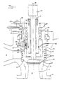
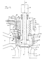
- Figs 1 and 2 show a valve device for control and closure of steam flow to for instance, steam turbines or steam reduction conduits.
- the valve device comprises a valve housing 1 with an inlet channel 2, an outlet channel 3 and a channel portion 4 located between these channels 2, 3.
- the valve housing 1 further comprises a valve seat 5 with an inlet side 6 and an outlet side 7.
- the valve seat 5, presenting a concentric centre axis 8, is arranged in the outlet channel 3 of the valve housing 1 in such a way that the outlet side 7 of the valve seat 5 forms the outlet channel 3 of the valve housing 1.
- the outlet channel 3 is designed to permit to be attached directly, for instance by means of a flange 9, to the next device in the steam flow process, for instance a steam turbine. Thereby, the steam flow can stream along a straight line from the inlet side 6 of the valve seat 5 straight into a steam turbine, for instance, without needing to be redirected.
- the valve device presents a control valve, arranged in the valve housing 1 and comprising a control valve cone body 10 and a spindle 11 connected thereto. At its other end, located outside the valve housing 1, the spindle 11 is connected to an actuator 12, not shown, through a coupling 12. By means of the actuator the control valve is displaceable along the centre axis 8 towards and away from the inlet side 6 of the valve housing 5.
- the valve device further presents a closing valve arranged in the valve housing 1 and comprising a valve cone body 13 which is designed as a ring-shaped bottomless sleeve.
- the closing valve forms a so called fast-closing valve which, during control errors or some other outer fault, very fast, that is within approximately 0,2 s, can shut off the steam flow and, in that way, immediately stop the steam turbine for example in an energency.
- the ring-shaped valve cone body 13 presents a centre axis coinciding with the centre axis 8 and is displaceably arranged in a ring-shaped spacing 14 towards and away from the inlet side 6 of the valve seat 5.
- the ring-shaped valve cone body 13 bears on the valve seat 5 around and outside the control valve cone body 10, see Fig 2.
- the ring-shaped valve cone body 13 thus stops the steam flow upstream of the control valve cone body 10.
- the valve device further presents a ring-shaped steam sleeve 15 which preferably is concentrically arranged outside the ring-shaped valve cone body 13.
- the steam sieve 15 presents guiding beams 16 which guide the steam flow from the inlet channel 2 in direction towards the inlet side 6 of the valve seat 5.
- a channel 17 extends to a pilot valve 18, and from the pilot valve 18 a channel 19 extends, on one hand, to the ring-shaped space 14, and, on the other hand, a channel 20 extends, which channel connects the pilot valve 18 with a low-pressure point, for instance downstream of a steam turbine.
- the pilot valve 18 comprises a valve cone body 21 which, in a first end position, closes the channel 20 and opens the channel 17 and, in a second end position, opens the channel 20 and closes the channel 17. Accordingly, in the first end position, the channel portion 4 is in connection with the ring-shaped spacing 14 so that the same high-pressure which exists in the channel portion 4 also will exist in the ring-shaped spacing 14. In the second end position of the valve cone body 21, the ring-shaped spacing 14 is in connection with the low-pressure point, so that a pressure which, in comparison with the pressure in the channel portion 4 is substantially lower, exists in the ring-shaped spacing 14.
- the pilot valve 18 is arranged on the valve housing 1 of the valve device. However, it may also be arranged at a distance from the valve device and be connected to the ring-shaped spacing 14 and the channel portion 4 by means of pressure conduits, see Fig 4. Furthermore, in the example shown, the channel 17 opens in the channel portion 4 inside of the steam sieve 15, whereby it is assured that no dirt particles can penetrate into the pilot valve 18 or the ring-shaped spacing 14. However, it is also possible to connect the channel 17 upstream of the steam sieve 15, for instance in order to save space in the valve housing 1.
- the ring-shaped valve cone body 13 presents a first free area Al in the ring-shaped spacing 14, as projected on a plane in relation to which the centre axis 8 forms a normal, and a second free area A2 in the channel portion 4, as projected on said plane, when the ring-shaped valve cone body 13 is in its closed position.
- the first free area Al is larger than the second free area A2.
- a compression spring 22 is arranged in the ring-shaped spacing 14 between an upper limitation wall 23 and the ring-shaped valve cone body 13. The spring force of the compression spring 22 acts upon the ring-shaped valve cone body 13 in closing direction.
- the free area in the channel portion 4 is just as large as the first free area Al. Accordingly, the force that is exerted by the pressure in the channel portion 4 upon the free area of the ring-shaped valve cone body 13 in the channel portion 4 will be larger than the spring force and, as the pressure is substantially lower in the ring-shaped spacing 14 than in the channel portion 4 when the ring shaped valve cone body 13 is in its open position and the pilot valve 18 is in the second end position, this force is sufficient to counteract the closure of the ring-shaped valve cone body 13.
- the ring-shaped, sleeve-like valve cone body 13 encloses, together with an upper limitation wall 24 of the channel portion 4, an inner spacing 25, at least when being in its closed position.
- the control valve cone body 10 can be accommodated in this inner spacing 25, that is the ring-shaped valve cone body 13 can be closed independently of the position of the control valve cone body 10.
- the inner spacing 25 is completely closed from the inlet channel 2 and the outlet channel 3, as seen in Fig 2.
- a pressure must thus be created in the inner spacing 25, which pressure is large enough, by the second free area A2 of the ring-shaped valve cone body 13, which area is accessible from the inner spacing 25, to overcome the spring force of the spring 22.
- the channel 26 is arranged in the wall of the ring-shaped valve cone body 13. Thereby, the same pressure can exist in the inner spacing 25 and the inlet channel 2. Due to the small cross-section of the channel 26 the control valve cone body 10 must be in a closed position to permit such a pressure equalizing to take place. This is an important safety aspect at steam turbine plants for instance.
- the channel 26 is only formed by a hole which extends through the wall of the ring-shaped valve cone body 13 and which is at such a height that it is situated in the channel portion 4 when the ring-shaped valve cone body 13 is closed, and is hidden in the ring-shaped spacing 14 when the ring-shaped valve cone body 13 is open.
- a second pilot valve 27 can be arranged in the ring-shaped valve cone body 13.
- the second pilot valve 27 presents a valve cone body 28 which is displaceably arranged in a recess 29 which extends parallel to the centre axis 8.
- the channel 26 presents an inlet part which connects the recess 29 with the channel portion 4, and an outlet part which connects the recess 29 with the inner spacing 25.
- the valve cone body 28 can be prestressed by means of a spring 30 towards a valve seat, arranged in the recess 29, for closing the channel 26. Furthermore, the valve cone body 28 of the second pilot valve 27 is, through a passage 31, connected to the ring-shaped spacing 14, so that the valve cone body 28 is pressed against the valve seat when a high-pressure exists in the ring-shaped spacing 14. Furthermore, the valve cone body 28 presents a piston-like part which bears on the wall of the recess 29 and a part which projects from the piston-like part and is to seal against the valve seat of the recess 29. Thereby, the spacing is formed in the recess 29 when the second pilot valve 27 is closed, in which spacing the inlet part of the channel 26 opens.
- the valve cone body of the second pilot valve 27 is designed in such a way that the area accessible for the high-pressure from above, that is from the ring-shaped spacing, is larger than the area accessible from below, that is from the spacing of the recess 29.
- the pressure of the steam flow will act upon the valve cone body of the second pilot valve 27 in closing direction. This closing action can be amplified by means of the spring 30.
- the overpressure in the spacing of the recess 29 will displace the valve cone body 28 to an open position, possibly also by overcoming the force of the spring 30. Therefore, if the control valve 10 is closed, the pressure can only be built up in the inner spacing 25 through the channel 26. When this pressure has been built up it will act upon the free area A2 and push the ring-shaped valve cone body 13 into the ring-shaped spacing 14 and, thus, open the closing valve 13.
- the compression spring 22 has been excluded.
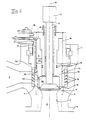
- the ring-shaped valve cone body has a stair-like design, so that the free area Al is substantially larger than the free area A2.
- the pressure will always act in a closing direction when the pilot valve 18 is in the first end position and the same pressure is present in the channel portion 4 and the ring-shaped spacing 14.
- Due to the stair-like design a closed spacing 32 is created between the wall of the ring-shaped spacing 14 and the wall of the ring-shaped cone body 13.
- This closed spacing 32 is, by means of a channel, not shown, connected to the low-pressure point to stop a possible pressure build-up in the closed spacing from being able to prevent the closure of the ring-shaped valve cone body 13.
- the channel 26 is shown without a second pilot valve. However, it is possible to arrange such a valve in the same way as in the first embodiment.
- the pressure upon the area Al which is the substantially larger one in comparison to the free area A2, will thus act in a closing direction when the pilot valve 18 is in the first end position.
- the pilot valve 18 is displaced to the second end position and the high-pressure in the ring-shaped spacing 14 disappears, the area accessible from the channel portion 4 is sufficient to open the closing valve 13 and keep it open.
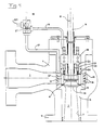
- Fig 4 shows a further embodiment which differs from the other embodiments through the pilot valve 18 being arranged at a distance from the valve housing 1 and the ring-shaped valve cone body 13 being displaceably arranged directly on the spindle 11 of the control valve cone body 10, the ring-shaped spacing 14 being formed between the valve housing 1 and the spindle 11.
- a bushing 33 is arranged therebetween.
- a sealing is arranged between the spindle 11 and the ring-shaped cone body 13.
- a plurality of sealing rings 34 are arranged in the valve housing between the ring-shaped spacing 14 and the ring-shaped valve cone body 13 to prevent unintentional pressure equalizing between the ring-shaped spacing 14 and the channel portion 4.
- the longitudinal axis of the inlet channel 2 and the longitudinal axis of the outlet channel 3 are arranged in a perpendicular angle to each other, other angles, obtuse as well as sharp ones, are possible.
- the longitudinal axes of these channels may be arranged in an obtuse angle in relation to each other to further improve the flow conditions and reduce the fall of pressure.
Landscapes
- Engineering & Computer Science (AREA)
- General Engineering & Computer Science (AREA)
- Mechanical Engineering (AREA)
- Lift Valve (AREA)
- Magnetically Actuated Valves (AREA)
- Details Of Valves (AREA)
- Valve Housings (AREA)
- Compressor (AREA)
- Electrically Driven Valve-Operating Means (AREA)
- Temperature-Responsive Valves (AREA)
- Multiple-Way Valves (AREA)
- Sliding Valves (AREA)
Claims (14)
- Ventilanordnung für die Einflußnahme auf einen Überdruckstrom eines Strömungsmittels, umfassend: ein Steuerventil (10) und ein Schließventil (13), die in einem gemeinsamen Ventilgehäuse (1) angeordnet sind, welches einen Kanalabschnitt (4) bildet und einen Auslaßkanal (3) und einen Einlaßkanal (2) aufweist, und einen gemeinsamen Ventilsitz (5), der in dem Ventilgehäuse (1) angeordnet ist und eine Einlaßseite (6) und eine Auslaßseite (7) aufweist, wobei das Steuerventil (10) derart ausgestaltet ist, daß es den Strom durch den Kanalabschnitt (4) steuert, das Schließventil (13) so ausgebildet ist, daß es entweder eine allgemein geschlossene Stellung oder eine allgemein geöffnete Stellung einnimmt, und das Schließventil (13) in seiner Offenstellung zumindest teilweise in einen Zwischenraum (14) ragt, der über ein Kanalelement (17, 19) mit dem Kanalabschnitt (4) stromaufwärts bezüglich des Schließventils (13) verbunden ist, das Steuerventil einen ersten Kegelkörper (10) aufweist, der in Richtung des Ventilsitzes (5) verlagerbar ist, und das Schließventil einen zweiten Kegelkörper (13) aufweist, der in Richtung des Ventilsitzes (5) verlagerbar und so ausgebildet ist, daß er an dem Ventilsitz (5) außerhalb des ersten Kegelkörpers und unabhängig von der Stellung des ersten Kegelkörpers anliegt, die Auslaßseite (7) des Ventilsitzes (5) den Auslaßkanal (3) des Ventilgehäuses bildet, welcher Kanal sich von den Kegelkörpern (10, 13) frei weg erstreckt, wobei in dem Kanalelement (17, 19) ein erstes Pilotventil (18) vorgesehen ist und in einer ersten Position die Verbindung zwischen dem Zwischenraum (14) und dem Kanalabschnitt (4) öffnet, um den Überdruck in dem Zwischenraum (14) herrschen zu lassen und das Schließen des Schließventils (13) herbeizuführen, und in einer zweiten Position das Öffnen des Schließventils (13) herbeizuführen, dadurch gekennzeichnet, daß das erste Pilotventil (18) derart ausgebildet ist, daß es das Schließventil (13) dadurch öffnet, daß es die Verbindung zwischen dem Zwischenraum (14) und dem Kanalabschnitt (4) schließt und eine Verbindung zwischen dem Zwischenraum (14) und einer Niederdruckstelle öffnet, um den in dem Zwischenraum (14) herrschenden Überdruck zu beseitigen.
- Ventilanordnung nach Anspruch 1, gekennzeichnet durch eine Einrichtung (11, 12) zum Steuern des Steuerventils.
- Ventilanordnung nach Anspruch 2, dadurch gekennzeichnet, daß die Steuereinrichtung (11, 12) und die Kanalelemente (17, 19) derart ausgebildet sind, daß sie sich in die gleiche Richtung weg von der Einlaßseite (6) des Ventilsitzes (5) erstrecken und dementsprechend vollständig außerhalb der Auslaßseite (7) gelegen sind.
- Ventilanordnung nach Anspruch 2 oder 3, dadurch gekennzeichnet, daß die Kanalelemente (17, 19) so ausgebildet sind, daß sie das Schließventil (13) mit Hilfe des Strömungsmittel-Überdrucks steuern.
- Ventilanordnung nach einem der vorhergehenden Ansprüche, dadurch gekennzeichnet, daß der Auslaßkanal (3) und der Einlaßkanal (2) miteinander einen Winkel in der Weise bilden, daß der Strom durch das Ventilgehäuse (1) nur einmal umgelenkt wird.
- Ventilanordnung nach einem der vorhergehenden Ansprüche, dadurch gekennzeichnet, daß die Ventilanordnung eine Mittelachse (8) bildet, um die herum der erste Kegelkörper (10) und der zweite Kegelkörper (13) angeordnet sind, und daß die Fläche des zweiten Kegelkörpers (13) in dem Zwischenraum (14), projiziert auf eine senkrecht zu der Achse verlaufende Ebene, größer ist als die freie Fläche des zweiten Kegelkörpers (13) innerhalb des Kanalabschnitts (4), projiziert auf diese Ebene, zumindest dann, wenn der Kegelkörper sich in seiner geschlossenen Stellung befindet.
- Ventilanordnung nach einem der vorhergehenden Ansprüche, dadurch gekennzeichnet, daß sich eine Feder (22) in dem Zwischenraum (14) befindet, wobei die Feder den zweiten Kegelkörper (13) in Schließrichtung vorspannt.
- Ventilanordnung nach einem der Ansprüche 1 bis 5, dadurch gekennzeichnet, daß die Ventilanordnung eine Mittelachse (8) definiert, um die herum der erste Kegelkörper (10) und der zweite Kegelkörper (13) angeordnet sind, und daß der zweite Kegelkörper (13) eine stufenförmige Ausgestaltung hat, die die Fläche des zweiten Kegelkörpers (13) innerhalb des Zwischenraums bei Projektion auf eine senkrecht zu der Achse verlaufende Ebene im wesentlichen größer macht als die freie Fläche des zweiten Kegelkörpers (13) in dem Kanalabschnitt (4), projiziert auf diese Ebene.
- Ventilanordnung nach einem der vorhergehenden Ansprüche, dadurch gekennzeichnet, daß der zweite Kegelkörper (13) ringförmig ist und einen Innenraum (25) umschließt, und daß der erste Kegelkörper (10) in den Innenraum (25) einführbar ist, so daß er von dem zweiten Kegelkörper umschlossen wird.
- Ventilanordnung nach Anspruch 9, dadurch gekennzeichnet, daß der zweite, ringförmige Kegelkörper (13) durch eine ringförmige Hülse ohne Boden gebildet wird, und daß der Zwischenraum, in den der zweite Kegelkörper einführbar ist, ringförmig ist.
- Ventilanordnung nach einem der Ansprüch 9 und 10, dadurch gekennzeichnet, daß in der Wand des ringförmigen zweiten Kegelkörpers (13) ein Kanal (26) in der Weise angeordnet ist, daß er eine Verbindung zwischen dem Kanalabschnitt (4) stromaufwärts bezüglich des Schließventils (13) und dem Innenraum (25) des Schließventils bildet, wenn das Schließventil sich in der geschlossenen Stellung befindet, um den Überdruck in dem Innenraum (25) herrschen zu lassen, wenn das Steuerventil (10) geschlossen ist, um dadurch das Öffnen des Schließventils (13) zu ermöglichen.
- Ventilanordnung nach Anspruch 11, dadurch gekennzeichnet, daß in dem Kanal (26) ein zweites Pilotventil (27) angeordnet ist, um den Kanal (26) zu öffnen, wenn der ringförmige Zwischenraum (14) mit der Niederdruckstelle verbunden ist, und um den Kanal (26) zu schließen, wenn der ringförmige Zwischenraum (14) mit dem Kanalabschnitt (4) verbunden ist.
- Ventilanordnung nach einem der Ansprüche 9 bis 12, dadurch gekennzeichnet, daß die Steuereinrichtung eine Spindel (11) aufweist, die von dem ringförmigen Zwischenraum (14) umgeben ist.
- Ventilanordnung nach einem der vorhergehenden Ansprüche, dadurch gekennzeichnet, daß um die Ventilkegelkörper (10, 13) herum ein Dampfsieb (15) angeordnet ist, welches Führungselemente (16) aufweist, um den Strömungsmittelstrom in Richtung der Einlaßseite (6) des Ventilsitzes (5) zu leiten.
Applications Claiming Priority (3)
| Application Number | Priority Date | Filing Date | Title |
|---|---|---|---|
| SE9501539A SE510173C2 (sv) | 1995-04-26 | 1995-04-26 | Ventilanordning |
| SE9501539 | 1995-04-26 | ||
| PCT/SE1996/000545 WO1996034219A1 (en) | 1995-04-26 | 1996-04-24 | A valve device |
Publications (2)
| Publication Number | Publication Date |
|---|---|
| EP0823030A1 EP0823030A1 (de) | 1998-02-11 |
| EP0823030B1 true EP0823030B1 (de) | 2001-06-27 |
Family
ID=20398094
Family Applications (1)
| Application Number | Title | Priority Date | Filing Date |
|---|---|---|---|
| EP96912378A Expired - Lifetime EP0823030B1 (de) | 1995-04-26 | 1996-04-24 | Ventilanordnung |
Country Status (11)
| Country | Link |
|---|---|
| US (1) | US5971018A (de) |
| EP (1) | EP0823030B1 (de) |
| JP (1) | JPH11504102A (de) |
| AT (1) | ATE202623T1 (de) |
| BR (1) | BR9608321A (de) |
| CA (1) | CA2217170A1 (de) |
| CZ (1) | CZ292317B6 (de) |
| DE (1) | DE69613574T2 (de) |
| PL (1) | PL179950B1 (de) |
| SE (1) | SE510173C2 (de) |
| WO (1) | WO1996034219A1 (de) |
Families Citing this family (13)
| Publication number | Priority date | Publication date | Assignee | Title |
|---|---|---|---|---|
| JP4016156B2 (ja) * | 1997-09-22 | 2007-12-05 | Smc株式会社 | スムースベントバルブ |
| DE19826076C1 (de) | 1998-06-12 | 1999-08-19 | Dungs Karl Gmbh & Co | Doppelsicherheitsventil |
| JP2005048922A (ja) * | 2003-07-31 | 2005-02-24 | Miura Co Ltd | バルブ |
| GB0517702D0 (en) | 2005-09-01 | 2005-10-05 | Alstom Technology Ltd | Valve assembly and related arrangements |
| EP2230431A1 (de) * | 2009-03-16 | 2010-09-22 | Siemens Aktiengesellschaft | Kompaktes Regel-Schnellschluss-Ventil für eine Dampfturbine |
| EP2230429A1 (de) * | 2009-03-16 | 2010-09-22 | Siemens Aktiengesellschaft | Platzsparendes Regel-Schnellschluss-Ventil für eine Dampfturbine |
| EP2937520B1 (de) * | 2012-12-21 | 2017-09-20 | Mitsubishi Hitachi Power Systems, Ltd. | Dampfventil und dampfturbine |
| CN104632299B (zh) * | 2014-12-02 | 2016-08-24 | 上海电气电站设备有限公司 | 汽轮机联合进汽阀 |
| JP6606407B2 (ja) * | 2015-11-12 | 2019-11-13 | 三菱日立パワーシステムズ株式会社 | 蒸気弁及び蒸気タービンシステム |
| WO2017193855A1 (zh) * | 2016-05-10 | 2017-11-16 | 比亚迪股份有限公司 | 膨胀开关阀 |
| JP7207999B2 (ja) | 2018-12-28 | 2023-01-18 | 三菱重工業株式会社 | 蒸気弁、発電システム、及び蒸気弁の検査方法 |
| JP7381226B2 (ja) * | 2019-06-17 | 2023-11-15 | 株式会社東芝 | 弁装置、発電設備および弁装置の弁座 |
| DE102019218694B4 (de) * | 2019-12-02 | 2023-01-05 | Turventil Gmbh & Co. Kg | Kombinationsventil aus Schnellschluss- und Regelventil für einen Dampfkreislauf |
Family Cites Families (6)
| Publication number | Priority date | Publication date | Assignee | Title |
|---|---|---|---|---|
| CH584350A5 (de) * | 1975-04-30 | 1977-01-31 | Bbc Brown Boveri & Cie | |
| CH584349A5 (de) * | 1975-04-30 | 1977-01-31 | Bbc Brown Boveri & Cie | |
| CH594156A5 (de) * | 1975-07-25 | 1977-12-30 | Sulzer Ag | |
| DE2533519A1 (de) * | 1975-07-26 | 1977-03-31 | Bbc Brown Boveri & Cie | Mehrzweckventil |
| AT366803B (de) * | 1979-06-15 | 1982-05-10 | C H Zikesch Ges Mit Beschraenk | Absperr- und regelventil |
| DE3242947A1 (de) * | 1982-11-20 | 1984-05-24 | Holstein Und Kappert Gmbh, 4600 Dortmund | Doppelsitzventil mit zwei ventiltellern |
-
1995
- 1995-04-26 SE SE9501539A patent/SE510173C2/sv not_active IP Right Cessation
-
1996
- 1996-04-24 EP EP96912378A patent/EP0823030B1/de not_active Expired - Lifetime
- 1996-04-24 AT AT96912378T patent/ATE202623T1/de not_active IP Right Cessation
- 1996-04-24 CZ CZ19973395A patent/CZ292317B6/cs not_active IP Right Cessation
- 1996-04-24 WO PCT/SE1996/000545 patent/WO1996034219A1/en not_active Ceased
- 1996-04-24 CA CA002217170A patent/CA2217170A1/en not_active Abandoned
- 1996-04-24 BR BR9608321-2A patent/BR9608321A/pt not_active IP Right Cessation
- 1996-04-24 JP JP8532440A patent/JPH11504102A/ja not_active Ceased
- 1996-04-24 US US08/945,349 patent/US5971018A/en not_active Expired - Lifetime
- 1996-04-24 DE DE69613574T patent/DE69613574T2/de not_active Expired - Lifetime
- 1996-04-24 PL PL96322975A patent/PL179950B1/pl not_active IP Right Cessation
Also Published As
| Publication number | Publication date |
|---|---|
| DE69613574T2 (de) | 2002-04-25 |
| EP0823030A1 (de) | 1998-02-11 |
| JPH11504102A (ja) | 1999-04-06 |
| PL322975A1 (en) | 1998-03-02 |
| ATE202623T1 (de) | 2001-07-15 |
| US5971018A (en) | 1999-10-26 |
| WO1996034219A1 (en) | 1996-10-31 |
| DE69613574D1 (de) | 2001-08-02 |
| SE510173C2 (sv) | 1999-04-26 |
| SE9501539D0 (sv) | 1995-04-26 |
| SE9501539L (sv) | 1996-10-27 |
| BR9608321A (pt) | 1999-11-30 |
| CZ339597A3 (cs) | 1999-01-13 |
| CZ292317B6 (cs) | 2003-09-17 |
| PL179950B1 (pl) | 2000-11-30 |
| CA2217170A1 (en) | 1996-10-31 |
Similar Documents
| Publication | Publication Date | Title |
|---|---|---|
| US5971018A (en) | Valve device for influencing an overpressurized flow of media | |
| US6655409B1 (en) | Combined stop and control valve for supplying steam | |
| CA1043219A (en) | Combined stop and control valve | |
| US7681592B2 (en) | Three-way poppet valves with floating seat | |
| CN102606784B (zh) | 用于三通阀的阀帽 | |
| EP2449294B1 (de) | Ventilvorrichtung und dampfturbinensystem mit besagter ventilvorrichtung | |
| US4506704A (en) | Distributing valve | |
| RU2766162C2 (ru) | Клапан со встроенным уравновешивающим каналом | |
| US20040238050A1 (en) | Control valve trim and seat design for valve trim with minimal unbalanced area | |
| EP2270370A1 (de) | Aktuatoranordnung für eine Ventilvorrichtung und Dampfturbinensystem mit besagter Ventilvorrichtung | |
| JP2872985B2 (ja) | 下流の翼形インサートを有する低騒音のボール弁組立体 | |
| CA1041982A (en) | Combined stop and control valve | |
| US12486925B2 (en) | Flow control valve | |
| US11746910B2 (en) | Plug integrated staged valve trim assembly and fluid control valve comprising same | |
| US4623119A (en) | Plug valve | |
| US20220107027A1 (en) | Anti-cavitation valve assembly | |
| US20240344489A1 (en) | Fuel injector for gaseous fuel and valve assembly for the same | |
| US5135032A (en) | Slurry gate valve | |
| JPH11351411A (ja) | 調整弁 | |
| GB2042687A (en) | Steam Turbine Control Valve | |
| CA2397035A1 (en) | Control valve stem split guide bushing | |
| WO2023149088A1 (ja) | 蒸気弁、及び発電システム | |
| EP0919897A2 (de) | Vorgesteuerter Gasdruckregler mit ausgeglichener Hülse | |
| US12385452B2 (en) | Fuel injector for gaseous fuel and valve assembly for the same | |
| US6024128A (en) | Valve assembly with integral phase regenerator |
Legal Events
| Date | Code | Title | Description |
|---|---|---|---|
| PUAI | Public reference made under article 153(3) epc to a published international application that has entered the european phase |
Free format text: ORIGINAL CODE: 0009012 |
|
| AK | Designated contracting states |
Kind code of ref document: A1 Designated state(s): AT DE FR GB IT |
|
| 17P | Request for examination filed |
Effective date: 19971028 |
|
| RTI1 | Title (correction) |
Free format text: VALVE DEVICE |
|
| GRAG | Despatch of communication of intention to grant |
Free format text: ORIGINAL CODE: EPIDOS AGRA |
|
| 17Q | First examination report despatched |
Effective date: 20000627 |
|
| GRAG | Despatch of communication of intention to grant |
Free format text: ORIGINAL CODE: EPIDOS AGRA |
|
| GRAH | Despatch of communication of intention to grant a patent |
Free format text: ORIGINAL CODE: EPIDOS IGRA |
|
| GRAH | Despatch of communication of intention to grant a patent |
Free format text: ORIGINAL CODE: EPIDOS IGRA |
|
| GRAA | (expected) grant |
Free format text: ORIGINAL CODE: 0009210 |
|
| AK | Designated contracting states |
Kind code of ref document: B1 Designated state(s): AT DE FR GB IT |
|
| PG25 | Lapsed in a contracting state [announced via postgrant information from national office to epo] |
Ref country code: AT Free format text: LAPSE BECAUSE OF FAILURE TO SUBMIT A TRANSLATION OF THE DESCRIPTION OR TO PAY THE FEE WITHIN THE PRESCRIBED TIME-LIMIT Effective date: 20010627 |
|
| REF | Corresponds to: |
Ref document number: 202623 Country of ref document: AT Date of ref document: 20010715 Kind code of ref document: T |
|
| RIN1 | Information on inventor provided before grant (corrected) |
Inventor name: PERSSON, LENNART Inventor name: KARLSSON, PER |
|
| REF | Corresponds to: |
Ref document number: 69613574 Country of ref document: DE Date of ref document: 20010802 |
|
| ITF | It: translation for a ep patent filed | ||
| ET | Fr: translation filed | ||
| REG | Reference to a national code |
Ref country code: GB Ref legal event code: IF02 |
|
| PLBE | No opposition filed within time limit |
Free format text: ORIGINAL CODE: 0009261 |
|
| STAA | Information on the status of an ep patent application or granted ep patent |
Free format text: STATUS: NO OPPOSITION FILED WITHIN TIME LIMIT |
|
| 26N | No opposition filed | ||
| PGFP | Annual fee paid to national office [announced via postgrant information from national office to epo] |
Ref country code: IT Payment date: 20090428 Year of fee payment: 14 Ref country code: FR Payment date: 20090424 Year of fee payment: 14 |
|
| PGFP | Annual fee paid to national office [announced via postgrant information from national office to epo] |
Ref country code: GB Payment date: 20090409 Year of fee payment: 14 |
|
| GBPC | Gb: european patent ceased through non-payment of renewal fee |
Effective date: 20100424 |
|
| REG | Reference to a national code |
Ref country code: FR Ref legal event code: ST Effective date: 20101230 |
|
| PG25 | Lapsed in a contracting state [announced via postgrant information from national office to epo] |
Ref country code: GB Free format text: LAPSE BECAUSE OF NON-PAYMENT OF DUE FEES Effective date: 20100424 Ref country code: IT Free format text: LAPSE BECAUSE OF NON-PAYMENT OF DUE FEES Effective date: 20100424 |
|
| PG25 | Lapsed in a contracting state [announced via postgrant information from national office to epo] |
Ref country code: FR Free format text: LAPSE BECAUSE OF NON-PAYMENT OF DUE FEES Effective date: 20100430 |
|
| PGFP | Annual fee paid to national office [announced via postgrant information from national office to epo] |
Ref country code: DE Payment date: 20150619 Year of fee payment: 20 |
|
| REG | Reference to a national code |
Ref country code: DE Ref legal event code: R071 Ref document number: 69613574 Country of ref document: DE |