EP0822915B1 - Process and device for cutting across a paper web - Google Patents
Process and device for cutting across a paper web Download PDFInfo
- Publication number
- EP0822915B1 EP0822915B1 EP96909042A EP96909042A EP0822915B1 EP 0822915 B1 EP0822915 B1 EP 0822915B1 EP 96909042 A EP96909042 A EP 96909042A EP 96909042 A EP96909042 A EP 96909042A EP 0822915 B1 EP0822915 B1 EP 0822915B1
- Authority
- EP
- European Patent Office
- Prior art keywords
- cutting
- paper web
- guide plate
- conveyor
- loop
- Prior art date
- Legal status (The legal status is an assumption and is not a legal conclusion. Google has not performed a legal analysis and makes no representation as to the accuracy of the status listed.)
- Expired - Lifetime
Links
Images

Classifications
-
- B—PERFORMING OPERATIONS; TRANSPORTING
- B65—CONVEYING; PACKING; STORING; HANDLING THIN OR FILAMENTARY MATERIAL
- B65H—HANDLING THIN OR FILAMENTARY MATERIAL, e.g. SHEETS, WEBS, CABLES
- B65H20/00—Advancing webs
- B65H20/30—Arrangements for accumulating surplus web
- B65H20/32—Arrangements for accumulating surplus web by making loops
-
- B—PERFORMING OPERATIONS; TRANSPORTING
- B26—HAND CUTTING TOOLS; CUTTING; SEVERING
- B26D—CUTTING; DETAILS COMMON TO MACHINES FOR PERFORATING, PUNCHING, CUTTING-OUT, STAMPING-OUT OR SEVERING
- B26D7/00—Details of apparatus for cutting, cutting-out, stamping-out, punching, perforating, or severing by means other than cutting
- B26D7/01—Means for holding or positioning work
- B26D7/02—Means for holding or positioning work with clamping means
- B26D7/025—Means for holding or positioning work with clamping means acting upon planar surfaces
-
- B—PERFORMING OPERATIONS; TRANSPORTING
- B65—CONVEYING; PACKING; STORING; HANDLING THIN OR FILAMENTARY MATERIAL
- B65H—HANDLING THIN OR FILAMENTARY MATERIAL, e.g. SHEETS, WEBS, CABLES
- B65H35/00—Delivering articles from cutting or line-perforating machines; Article or web delivery apparatus incorporating cutting or line-perforating devices, e.g. adhesive tape dispensers
- B65H35/04—Delivering articles from cutting or line-perforating machines; Article or web delivery apparatus incorporating cutting or line-perforating devices, e.g. adhesive tape dispensers from or with transverse cutters or perforators
- B65H35/06—Delivering articles from cutting or line-perforating machines; Article or web delivery apparatus incorporating cutting or line-perforating devices, e.g. adhesive tape dispensers from or with transverse cutters or perforators from or with blade, e.g. shear-blade, cutters or perforators
-
- B—PERFORMING OPERATIONS; TRANSPORTING
- B65—CONVEYING; PACKING; STORING; HANDLING THIN OR FILAMENTARY MATERIAL
- B65H—HANDLING THIN OR FILAMENTARY MATERIAL, e.g. SHEETS, WEBS, CABLES
- B65H2301/00—Handling processes for sheets or webs
- B65H2301/50—Auxiliary process performed during handling process
- B65H2301/51—Modifying a characteristic of handled material
- B65H2301/512—Changing form of handled material
- B65H2301/5121—Bending, buckling, curling, bringing a curvature
- B65H2301/51212—Bending, buckling, curling, bringing a curvature perpendicularly to the direction of displacement of handled material, e.g. forming a loop
Definitions
- the invention relates to a device for cross cutting a paper web with a stationary cutting tool, which has cooperating cutting knives with one arranged in front of the cutting tool during the Operation of the device continuously driven first conveyor, by means of which the paper web between two successive cutting operations is each supplied in a predetermined length with a in the area between the first conveyor and the Cutting tool provided, driven synchronously with this Clamping device, by means of which the immediate adjacent to the cutting tool, lying in front of this Area of the paper web for the duration of the cutting process can be clamped until the passage between the Cutting knives is free again, and with one in the area between the first conveyor and the clamping device provided space in which the during the cutting process from the first conveyor continuously fed paper web section in the form of a theoretically straight versus Extend the feed direction transversely to the arched loop can.
- the paper web When post-processing printed paper webs, e.g. of computer printouts, the paper web is said to be in cut individual sheets of paper with a form height e.g. can be between 3 "and 12".
- a form height e.g. can be between 3 "and 12".
- automatic cutting machines that are next to one Cutting tool, which is used for cross cutting the paper web is also equipped with cutting tools, which cut off the perforated edges of the paper web or can also split them lengthways.
- a such cutting machine that has been used in practice has proven itself excellently is in the prospectus B ⁇ WE SYSTEC AG, D-86135 Augsburg, "B ⁇ WE automatic cutting machine 310 ", 3/94. This automatic cutting machine processes zigzag folded, printed paper webs.
- A, 31 31 101 is a device for cross cutting a paper web of the type mentioned known in which one in front of the clamping device second conveyor, consisting of a continuous driven upper conveyor roller and one from below this pressable lower conveyor roller, which can be lowered from the upper conveyor roller is provided.
- the conveyor roller is synchronized with the drive of the clamping device or the cutting knife of the kind that before a cut first the paper web in the clamping device clamped and at the same time the lower one Conveyor roller is lowered down. Because of that comes the paper web to a standstill and also the second Conveyor no longer acts on the paper web on.
- the invention is therefore based on the object Device for cross cutting a paper web to create the kind mentioned at the beginning, with which also at very high paper feed speeds and high cutting frequency a high cutting accuracy achieved and at the same time the noise pollution is significant is reduced.
- the damping hood is in combination with the Openings provided with guide plate also very high paper feed speeds and high Cutting frequencies for great cutting accuracy. Even at paper feed speeds over 0.8 m / sec. and a cutting frequency of over 10 cuts / sec. are cutting accuracies in the tenths of a millimeter range achieved with a tolerance of ⁇ 0.3 mm. This is due to the fact that inside the damping hood defined and constant air pressure conditions are present during the loop formation Environmental influences, such as air currents, heat effects and the like. Keep away from the loop. Also be Vibrations of the loop are damped and as a result an orderly, reproducible loop formation is ensured. The arrangement is also in this context of the perforated guide plate from Importance.
- the guide plate ensures that the loop only ever in one direction can train, the breakthroughs being crucial Importance. Because of the breakthroughs air in during the swirling of the loop the space between the loop and the guide plate come in quickly, but especially the air escape quickly from this room again when after End the cutting process through the loop the second conveyor is pulled flat again.
- the invention enables the cutting performance approx. 80,000 cuts / hour at a form height of 3 ". Thanks to the high cutting performance it is possible to do the cross cutting on line afterwards perform a laser printer, which has other advantages brings with it.
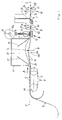
- the device for cross cutting a paper web has according to the embodiment shown in Figures 1 and 2 a cutting tool 1 with a stationary cutting knife 2 and an up and down movable cutting knife 3 on.
- a first is at a distance from the cutting tool 1
- Conveyor 4 is provided, which in this embodiment is designed as a so-called tractor.
- the tractor consists of two arranged parallel to each other Conveyor belts 5 with their spikes 6 in perforations engage on both longitudinal edges of the paper web 7.
- the conveyor 4 is continuously with a Peripheral speed V1 driven, e.g. the delivery speed an upstream, not shown Corresponds to the laser printer.
- V1 driven Peripheral speed
- This clamping device 8 is preferably nearby of the cutting tool 1, i.e. their distance from the cutting tool 1 is less than its distance to the conveyor 4.
- a third is expedient behind the cutting tool 1 Conveyor 10 is provided, which is also continuous is driven at a conveying speed V2, the conveyor speed V2 of the second Conveyor 9 corresponds.
- the clamping device 8 comprises two jaws 11, the in the transverse direction of the paper web 7 at a distance from one another are arranged and of which only one in the drawing is shown. These jaws 11 act with a stationary pad 12 together. Each jaw 11 is at one (lower) end of a cross to the feed direction A arranged the paper web 7 movable plunger 13, whose other (upper) end carries a roller 14, which cooperates with a cam disc 15.
- the cam disc 15 can be driven synchronously with the cutting tool 1.
- a common Belt drive may be provided.
- the belt drive also drives the movable cutting knife 3.
- the belt drive is expediently driven continuous, but it can also be intermittent be.
- the second conveyor 9 and the third conveyor 10 appropriately each have a continuous drivable conveyor roller 20 or 21 and at least an axially parallel pressure roller 22, 23 on the under elastic prestress 24 on the conveyor roller 20 or 21 is present.
- the elastic bias 24 is preferred adjustable.
- the drive of the two conveyor rollers 20, 21 can for example by a third Engine. This third engine gives the Conveyor rollers 20, 21 a conveyor speed V2, the for example four times the conveying speed V1 of the first conveyor 4.
- a bulging device 25 is provided, which on the paper web 7, at least at times a cross to the feed direction A directed force P exerts. If the feed direction A, as in the embodiment shown in Figures 1 and 2 the case is essentially horizontal, then the force P should be directed upwards. This has the advantage that the feed during the cutting process stored paper web section 7a after the release of the clamping device 8 also by Gravity is supported, as detailed below is described.
- a guide plate can first be used to generate the force P.
- 26 may be provided, which compared to the Conveyor elements 5 of the first conveyor 4 and Clamping elements 11, 12 tangential to the clamping device 8 Level E-E arched transversely to feed direction A. is. In the illustrated embodiment the bulge 26a takes place upwards.
- the movable cutting knife 3 can are also driven continuously so that alternately a cutting process is carried out or the passage between the cutting blades 2 and 3 is released is. While the latter is the case, too the clamping device 8 opened so that the paper web 7 by the conveyors 4 and 9 and larger ones Format heights also by the conveyor 10 in Direction A is moved on.
- the conveyor rollers 20, 21 of the second conveyor 9 and the third conveyor 10 continue to rotate.
- the movable cutting knife 3 goes down and cuts a paper sheet 7b in the desired format height, which is immediately carried out by the third conveyor 10 is moved on.
- the conveyor rollers 20, 21 have one smooth steel surface and the elastic preload 24 is adjusted so that the conveyor rollers 20, 21st can continue to rotate while clamping the paper web, without damaging it.
- the second conveyor promotes 9 the end adjacent to the cutting device 1 the paper web with a conveying speed V2 further, which is higher than the conveying speed V1 the first conveyor 4.
- This will stored loop 7a removed.
- the moving on of the paper web section stored in the form of the loop 7a is also generated by the in the loop Tension favors the free end of the paper web pushes towards the cutting tool 1.
- the loop 7a cannot expand backwards, because paper web constantly through the first conveyor 4 is funded.
- gravity will still take effect, which is the loop 7a pushes down and thereby the paper web in Moved towards the cutting tool 1.
- the second Conveyor 9 therefore only needs that in shape the loop stored small paper web section 7a to move further, this further movement by the voltage built up during the clamping and the Gravity is favored.
- Holding the paper web can be done in other ways done, for example, by clamps on the edge attack the paper web. The only thing that matters is that the clamping device is synchronous with the cutting tool is driven so that the clamping device holds the paper web during the cutting process.
- the guide plate 26 is curved upwards, the Bulging through an angled portion 26b of the guide plate is achieved.
- the guide plate 26 is still with a Plurality of openings 36, e.g. circular holes, Mistake. Through these openings 36 can during Bulge of the loop air between the loop and the guide plate can enter quickly, in particular however, the air from the space between the loop 7a and escape the guide plate 26 quickly if after Completion of the cutting process through the loop second conveyor 9 is pulled flat again.
- the paper web 7 comes on the bend 26b to the facility.
- Friction is achieved that the second Conveyor tension exerted on the paper web not fully up to the first conveyor 4 can reproduce.
- baffles influencing the formation of the loop 37, 38 provided in the front and rear area of the guide plate 26 inclined opposite one another above it.
- These baffles 37, 38 are for Support for even loop formation.
- the guide plates 37, 38 ensure that the loops are always in roughly the same place and that the loop is not in the feed direction A walks forward or backward.
- the Baffles 37, 38 make the loop formation reproducible.
- the inclination of each baffle 37, 38 adjustable relative to the guide plate 26 is.
- the guide plates 37, 38 by one in each case transverse to the feed direction A.
- the room is above the Guide plates 26 and above the guide plates 37, 38 enclosed by a damping hood 41.
- the Damping hood 41 should be at a greater distance be arranged by the loop 7a so that it is still sufficient Air space between the loop 7a and the inside of the Damping hood is present.
- the damping hood acts on the one hand as an air chamber, which is used for loop formation vibrations occurring at high speeds dampens and it also serves for sound insulation.
Description
Die Erfindung betrifft eine Vorrichtung zum Querschneiden einer Papierbahn, mit einem stationären Schneidwerkzeug, welches zusammenarbeitende Schneidmesser aufweist, mit einer vor dem Schneidwerkzeug angeordneten, während des Betriebes der Vorrichtung kontinuierlich angetriebenen ersten Fördereinrichtung, mittels der die Papierbahn zwischen zwei aufeinanderfolgenden Schneidevorgängen jeweils in vorbestimmter Länge zugeführt wird, mit einer im Bereich zwischen der ersten Fördereinrichtung und dem Schneidwerkzeug vorgesehenen, synchron mit diesem angetriebenen Klemmeinrichtung, mittels welcher der unmittelbar an das Schneidwerkzeug angrenzende, vor diesem liegende Bereich der Papierbahn für die Dauer des Schneidevorgangs festklemmbar ist, bis der Durchgang zwischen den Schneidmessern wieder frei ist, und mit einem im Bereich zwischen der ersten Fördereinrichtung und der Klemmeinrichtung vorgesehenen Freiraum, in welchem sich der während des Schneidevorganges von der ersten Fördereinrichtung kontinuierlich nachgeförderte Papierbahnabschnitt in Form einer gegenüber der theoretisch geraden Vorschubrichtung quer hierzu ausgewölbten Schlaufe ausdehnen kann.The invention relates to a device for cross cutting a paper web with a stationary cutting tool, which has cooperating cutting knives with one arranged in front of the cutting tool during the Operation of the device continuously driven first conveyor, by means of which the paper web between two successive cutting operations is each supplied in a predetermined length with a in the area between the first conveyor and the Cutting tool provided, driven synchronously with this Clamping device, by means of which the immediate adjacent to the cutting tool, lying in front of this Area of the paper web for the duration of the cutting process can be clamped until the passage between the Cutting knives is free again, and with one in the area between the first conveyor and the clamping device provided space in which the during the cutting process from the first conveyor continuously fed paper web section in the form of a theoretically straight versus Extend the feed direction transversely to the arched loop can.
Bei der Nachverarbeitung von bedruckten Papierbahnen, z.B. von Computerausdrucken, soll die Papierbahn in einzelne Papierblätter mit einer Vordruckhöhe geschnitten werden, die z.B. zwischen 3" und 12" liegen kann. Zu diesem Zweck gibt es Schneideautomaten, die neben einem Schneidwerkzeug, welches zum Querschneiden der Papierbahn dient, auch mit Schneidwerkzeugen ausgerüstet sind, welche die perforierten Ränder der Papierbahn abschneiden oder diese auch in Längsrichtung teilen können. Ein solcher Schneidautomat, der sich in der Praxis bisher hervorragend bewährt hat, ist in dem Prospekt der BÖWE SYSTEC AG, D-86135 Augsburg, "Schneideautomat BÖWE 310", 3/94, beschrieben. Dieser Schneideautomat verarbeitet zickzackförmig gefalzte, bedruckte Papierbahnen. Er weist zum Querschneiden ein aus einem ruhenden und einem auf- und abbeweglichen Schneidmesser bestehendes Schneidwerkzeug auf. Vor diesem Schneidwerkzeug ist eine erste Fördereinrichtung angeordnet, die als sogenannter Traktor ausgebildet ist. Dieser besteht aus zwei parallel zueinander angeordneten, endlosen Transportbändern, die mit ihren Stacheln in Perforation an beiden Rändern der Papierbahn eingreifen. Dieser bekannte Schneidautomat arbeitet nach dem Start-Stopp-Prinzip. Während die Schneidmesser voneinander entfernt und der Durchgang zwischen ihnen freigegeben ist, fördert der Traktor die Papierbahn jeweils um eine der Formathöhe entsprechende Länge weiter. Dann stoppt der Traktor und die Schneidmesser des Schneidwerkzeuges führen den Schneidevorgang durch. Sobald der Durchgang zwischen dem Schneidmesser wieder frei ist, wird der Traktor erneut gestartet. Obwohl die Schneidleistung dieser bekannten Schneidautomaten mit etwa 27000 Schnitten pro Stunde, bei einer Vordruckhöhe von 3" (= 7,5 Schnitte/s), schon recht hoch ist, entspricht sie nicht mehr zukünftigen Anforderungen. Moderne Datenverarbeitungsanlagen arbeiten mit Laserdruckern mit so hoher Geschwindigkeit, daß der bekannte Schneidautomat nicht in der Lage wäre, die vom Laserdrucker ausgedruckte Papierbahn on line, d.h. im Anschluß an den Drucker mit einer der Arbeitsgeschwindigkeit des Druckers entsprechenden Geschwindigkeit, zu zerschneiden. Die Arbeitsgeschwindigkeit des bekannten Schneidautomaten läßt sich auch nicht mehr wesentlich steigern. Dies ist durch das Start-Stopp-Prinzip systembedingt. Vor jedem Schnitt muß die Papierbahn stillgesetzt und nach jedem Schnitt vom Stillstand innerhalb von Bruchteilen einer Sekunde wieder auf die volle Fördergeschwindigkeit beschleunigt werden und dies mehr als 30.000 x pro Stunde. Die bei noch größerer Schnittleistung auf die Papierbahn einwirkenden Beschleunigungskräfte sind so groß, daß die Randperforationen ausreißen können und, falls die Papierbahn mit Querperforation versehen ist, diese an den Querperforationen reißt.When post-processing printed paper webs, e.g. of computer printouts, the paper web is said to be in cut individual sheets of paper with a form height e.g. can be between 3 "and 12". To for this purpose there are automatic cutting machines that are next to one Cutting tool, which is used for cross cutting the paper web is also equipped with cutting tools, which cut off the perforated edges of the paper web or can also split them lengthways. A such cutting machine that has been used in practice has proven itself excellently is in the prospectus BÖWE SYSTEC AG, D-86135 Augsburg, "BÖWE automatic cutting machine 310 ", 3/94. This automatic cutting machine processes zigzag folded, printed paper webs. It shows a cross from a resting and an up and down movable cutting knife existing Cutting tool. Before this cutting tool is arranged a first conveyor, the so-called Tractor is trained. This consists of two endless conveyor belts arranged parallel to each other, the ones with their spikes in perforation engage both edges of the paper web. This well-known The cutting machine works according to the start-stop principle. While the cutting knives are apart and the Passage between them is encouraged Tractor the paper web by one of the format height appropriate length further. Then the tractor stops and the cutting knife of the cutting tool lead the Cutting process through. Once the passage between the cutting knife is free again, the tractor started again. Although the cutting performance of this known cutting machines with about 27,000 cuts per hour, at a form height of 3 "(= 7.5 cuts / s), is already quite high, it no longer corresponds to future ones Conditions. Modern data processing systems work with laser printers at such high speed, that the well-known cutting machine is not in the The paper web printed out by the laser printer would be in a position on line, i.e. following the printer with one that corresponds to the operating speed of the printer Speed to cut up. The Working speed of the known cutting machine can no longer be increased significantly. This is system-dependent due to the start-stop principle. The paper web must be stopped before each cut and after each cut from standstill within Fractions of a second back to full conveyor speed be accelerated and this more than 30,000 x per hour. The with even greater cutting performance acceleration forces acting on the paper web are so big that the edge perforations tear out can and, if the paper web with cross perforation is provided, this on the transverse perforations tears.
Aus der DE,A,31 31 101 ist eine Vorrichtung zum Querschneiden einer Papierbahn der eingangs genannten Art bekannt, bei welcher vor der Klemmeinrichtung eine zweite Fördereinrichtung, bestehend aus einer kontinuierlich angetriebenen oberen Förderrolle und einer von unten an diese andrückbaren unteren Förderrolle, die von der oberen Förderrolle nach unten absenkbar ist, vorgesehen ist. Die Absenkbewegung der unteren Förderrolle erfolgt synchron mit dem Antrieb der Klemmeinrichtung bzw. des Schneidmessers der Art, daß vor einem Schnitt zunächst die Papierbahn in der Klemmeinrichtung festgeklemmt und gleichzeitig die untere Förderrolle nach unten abgesenkt wird. Dadurch kommt die Papierbahn zum Stillstand und auch die zweite Fördereinrichtung wirkt nicht länger auf die Papierbahn ein. Da die erste Fördereinrichtung kontinuierlich weiterfördert, wird die Papierbahn gestaut und es bildet sich zwischen der ersten und der zweiten Fördereinrichtung eine frei nach unten hängende Schlaufe aus. Während der Klemmung der Papierbahn erfolgt das Querschneiden derselben mittels des Schneidwerkzeuges. Nach beendetem Schnitt wird die Klemmung wieder aufgehoben und die untere Förderrolle wird an die obere Förderrolle der zweiten Fördereinrichtung angedrückt. Da diese mit höherer Fördergeschwindigkeit arbeitet als die erste Fördereinrichtung, wird die während des Querschneidens gebildete Schlaufe wieder flachgezogen. Es hat sich jedoch gezeigt, daß bei höheren Papier-Vorschubgeschwindigkeiten über 0,5 m/Sek. und dementsprechend hoher Schnittfrequenz die Schlaufenbildung nicht mehr geordnet und reproduzierbar verläuft. Aus den chaotischen Verhältnissen bei der Schlaufenbildung resultieren vor allem Schnittungenauigkeiten in Bezug auf die Länge der abgeschnittenen Papierblätter, die außerhalb der vorgegebenen Toleranzen liegen. Außerdem tritt durch die rasche Aufeinanderfolge von Schlaufenbildung und Flachziehen der Schlaufe eine erhebliche Lärmbelästigung auf.From DE, A, 31 31 101 is a device for cross cutting a paper web of the type mentioned known in which one in front of the clamping device second conveyor, consisting of a continuous driven upper conveyor roller and one from below this pressable lower conveyor roller, which can be lowered from the upper conveyor roller is provided. The lowering movement of the lower one The conveyor roller is synchronized with the drive of the clamping device or the cutting knife of the kind that before a cut first the paper web in the clamping device clamped and at the same time the lower one Conveyor roller is lowered down. Because of that comes the paper web to a standstill and also the second Conveyor no longer acts on the paper web on. Since the first conveyor continuously conveyed further, the paper web is jammed and forms it between the first and the second conveyor a loop hanging freely down out. This happens during the clamping of the paper web Cross cutting the same using the cutting tool. When the cut is complete, the clamping is released and the lower conveyor roller is attached to the upper one Pressed conveyor roller of the second conveyor. Since this works at a higher conveying speed as the first conveyor, the during of the cross-cut loop drawn flat again. However, it has been shown that at higher Paper feed speeds over 0.5 m / sec. and accordingly high cutting frequency the loop formation is no longer organized and reproducible. From the chaotic conditions at Loop formation primarily results in inaccurate cuts in terms of the length of the clipped Sheets of paper outside the specified tolerances lie. In addition, the rapid succession occurs of loop formation and pulling the loop flat considerable noise pollution.
Der Erfindung liegt daher die Aufgabe zugrunde, eine Vorrichtung zum Querschneiden einer Papierbahn der eingangs erwähnten Art zu schaffen, mit welcher auch bei sehr hohen Papier-Vorschubgeschwindigkeiten und hoher Schnittfrequenz eine hohe Schnittgenauigkeit erreicht und gleichzeitig die Lärmbelästigung wesentlich reduziert wird.The invention is therefore based on the object Device for cross cutting a paper web to create the kind mentioned at the beginning, with which also at very high paper feed speeds and high cutting frequency a high cutting accuracy achieved and at the same time the noise pollution is significant is reduced.
Dies wird nach der Erfindung dadurch erreicht, daß zwischen der ersten Fördereinrichtung und der Klemmeinrichtung ein Führungsblech vorgesehen ist, daß das Führungsblech mit einer Vielzahl von Durchbrechungen versehen ist und daß der Raum oberhalb des Führungsbleches von einer Dämpfungshaube umschlossen ist, die mit Abstand von der Schlaufe angeordnet ist.This is achieved according to the invention in that between the first conveyor and the clamping device a guide plate is provided that the guide plate with a large number of openings is provided and that the space above the guide plate is enclosed by a damping hood that is arranged at a distance from the loop.
Die Dämpfungshaube führt in Kombination mit dem mit Durchbrechungen versehenen Führungsblech auch bei sehr hohen Papier-Vorschubgeschwindigkeiten und hohen Schnittfrequenzen zu einer großen Schnittgenauigkeit. Auch bei Papiervorschubgeschwindigkeiten über 0,8 m/Sek. und einer Schnittfrequenz von über 10 Schnitten/Sek. werden Schnittgenauigkeiten im Zehntel-Millimeter-Bereich mit einer Toleranz ± 0,3 mm erreicht. Dies ist darauf zurückzuführen, daß innerhalb der Dämpfungshaube definierte und gleichbleibende Luftdruckverhältnisse vorhanden sind, die während der Schlaufenbildung Umgebungseinflüsse, wie Luftströmungen, Wärmeeinwirkungen und dgl. von der Schlaufe fernhalten. Außerdem werden Schwingungen der Schlaufe gedämpft und hierdurch eine geordnete, reproduzierbare Schlaufenbildung sichergestellt. In diesem Zusammenhang ist auch die Anordnung des mit Durchbrechungen versehenen Führungsbleches von Wichtigkeit. Das Führungsblech sorgt dafür, daß sich die Schlaufe immer nur in einer Richtung nach oben ausbilden kann, wobei den Durchbrechungen entscheidende Bedeutung zukommt. Durch die Durchbrechungen kann nämlich während des Auswirbelns der Schlaufe Luft in den Raum zwischen der Schlaufe und dem Führungsblech rasch eintreten, insbesondere kann jedoch die Luft aus diesem Raum wieder rasch entweichen, wenn nach Beendigung des Schneidevorgangs die Schlaufe durch die zweite Fördereinrichtung wieder flachgezogen wird. Die Erfindung ermöglicht es, die Schnittleistung auf ca. 80.000 Schnitte/Std. bei einer Vordruckhöhe von 3" zu steigern. Dank der hohen Schnittleistung ist es möglich, das Querschneiden on line im Anschluß an einen Laserdrucker durchzuführen, was weitere Vorteile mit sich bringt.The damping hood is in combination with the Openings provided with guide plate also very high paper feed speeds and high Cutting frequencies for great cutting accuracy. Even at paper feed speeds over 0.8 m / sec. and a cutting frequency of over 10 cuts / sec. are cutting accuracies in the tenths of a millimeter range achieved with a tolerance of ± 0.3 mm. This is due to the fact that inside the damping hood defined and constant air pressure conditions are present during the loop formation Environmental influences, such as air currents, heat effects and the like. Keep away from the loop. Also be Vibrations of the loop are damped and as a result an orderly, reproducible loop formation is ensured. The arrangement is also in this context of the perforated guide plate from Importance. The guide plate ensures that the loop only ever in one direction can train, the breakthroughs being crucial Importance. Because of the breakthroughs air in during the swirling of the loop the space between the loop and the guide plate come in quickly, but especially the air escape quickly from this room again when after End the cutting process through the loop the second conveyor is pulled flat again. The invention enables the cutting performance approx. 80,000 cuts / hour at a form height of 3 ". Thanks to the high cutting performance it is possible to do the cross cutting on line afterwards perform a laser printer, which has other advantages brings with it.
Vorteilhafte Ausgestaltungen der Erfindung sind in den Unteransprüchen gekennzeichnet.Advantageous embodiments of the invention are in the Subclaims marked.
Die Erfindung ist in folgendem, anhand eines in der Zeichnung dargestellten Ausführungsbeispieles näher erläutert Es zeigen:
Figur 1- einen Längsschnitt der Vorrichtung zum Querschneiden einer Papierbahn,
Figur 2- einen Teillängsschnitt dieser Vorrichtung im Bereich der Schlaufenbildung in einem größeren Maßstab,
- Figur 3
- eine Teildraufsicht in Richtung III der
Figur 2.
- Figure 1
- 2 shows a longitudinal section of the device for cross cutting a paper web,
- Figure 2
- a partial longitudinal section of this device in the area of loop formation on a larger scale,
- Figure 3
- a partial plan view in the direction III of Figure 2.
Die Vorrichtung zum Querschneiden einer Papierbahn weist
gemäß dem in Figur 1 und 2 dargestellten Ausführungsbeispiel
ein Schneidwerkzeug 1 mit einem stationären Schneidmesser
2 und einem auf- und abbeweglichen Schneidmesser 3
auf. In Abstand vor dem Schneidwerkzeug 1 ist eine erste
Fördereinrichtung 4 vorgesehen, welche bei diesem Ausführungsbeispiel
als sogenannter Traktor ausgebildet ist.
Der Traktor besteht aus zwei parallel zueinander angeordneten
Förderbändern 5, die mit ihren Stacheln 6 in Perforationen
an beiden Längsrändern der Papierbahn 7 eingreifen.
Die Fördereinrichtung 4 wird kontinuierlich mit einer
Umfangsgeschwindigkeit V1 angetrieben, die z.B. der Liefergeschwindigkeit
eines vorgeschalteten, nicht dargestellten
Laserdruckers entspricht. Im Bereich zwischen der Fördereinrichtung
4 und dem Schneidwerkzeug 1 ist eine synchron
mit diesem angetriebene Klemmeinrichtung 8 vorgesehen.
Diese Klemmeinrichtung 8 ist vorzugsweise in der Nähe
des Schneidwerkzeuges 1 angeordnet, d.h. ihr Abstand
von dem Schneidwerkzeug 1 ist geringer als ihr Abstand
zur Fördereinrichtung 4. The device for cross cutting a paper web has
according to the embodiment shown in Figures 1 and 2
a
Zwischen der Klemmeinrichtung 8, die nachstehend noch
näher beschrieben, wird, und dem Schneidwerkzeug 1 ist
vorzugsweise unmittelbar angrenzend an dieses eine
kontinuierlich angetriebene, zweite Fördereinrichtung 9
angeordnet, deren Fördergeschwindigkeit (= Umfangsgeschwindigkeit)
V2 größer ist als die Fördergeschwindigkeit
V1 der ersten Fördereinrichtung 4.Between the
Hinter dem Schneidwerkzeug 1 ist zweckmäßig eine dritte
Fördereinrichtung 10 vorgesehen, die ebenfalls kontinuierlich
angetrieben wird und zwar mit einer Fördergeschwindkeit
V2, die der Fördergeschwindigkeit V2 der zweiten
Fördereinrichtung 9 entspricht.A third is expedient behind the
Die Klemmeinrichtung 8 umfaßt zwei Klemmbacken 11, die
in Querrichtung der Papierbahn 7 in Abstand voneinander
angeordnet sind und von denen in der Zeichnung nur einer
dargestellt ist. Diese Klemmbacken 11 wirken mit einer
stationären Unterlage 12 zusammen. Jeder Klemmbacken 11
ist an dem einen (unteren) Ende eines quer zur Vorschubrichtung
A der Papierbahn 7 beweglichen Stößels 13 angeordnet,
dessen anderes (oberes) Ende eine Rolle 14 trägt,
die mit einer Nockenscheibe 15 zusammenwirkt. Die Nockenscheibe
15 ist synchron mit dem Schneidwerkzeug 1 antreibbar.
Zu diesem Zweck kann ein gemeinsamer
Riementrieb vorgesehen sein.
Der Riementrieb treibt auch
das bewegliche Schneidmesser 3 an.
Der Antrieb des Riementriebes erfolgt zweckmäßig
kontinuierlich, er kann jedoch auch intermittierend
sein. Die Antriebsgeschwindigkeit n des Riementriebes
ist in Abhängigkeit von der Fördergeschwindigkeit V1
der ersten Fördereinrichtung 4 so einstellbar, daß immer
dann ein Schnitt erfolgt, wenn die Papierbahn 7 durch
die Fördereinrichtung 4 gegenüber dem Schneidwerkzeug 1
um eine der gewünschten Formathöhe (= Vordruckhöhe)
entsprechende Länge weiterbewegt wurde.The
Die zweite Fördereinrichtung 9 und die dritte Fördereinrichtung
10 weisen zweckmäßig jeweils eine kontinuierlich
antreibbare Förderrolle 20 bzw. 21 und mindestens
eine hierzu achsparallele Andruckrolle 22, 23 auf, die
unter elastischer Vorspannung 24 an der Förderrolle 20
bzw. 21 anliegt. Die elastische Vorspannung 24 ist vorzugsweise
einstellbar. Der Antrieb der beiden Förderrollen
20, 21 kann beispielsweise durch einen dritten
Motor erfolgen. Dieser dritte Motor erteilt den
Förderrollen 20, 21 eine Fördergeschwindigkeit V2, die
beispielsweise viermal so groß ist wie die Fördergeschwindigkeit
V1 der ersten Fördereinrichtung 4.The second conveyor 9 and the
Ferner ist zwischen der ersten Fördereinrichtung
4 und der Klemmeinrichtung 9 eine Auswölbeeinrichtung
25 vorgesehen, welche auf die Papierbahn 7,
zumindest zeitweise eine quer zur Vorschubrichtung A
gerichtete Kraft P ausübt. Wenn die Vorschubrichtung A,
wie es bei dem in Figur 1 und 2 dargestellten Ausführungsbeispiel
der Fall ist, im wesentlichen horizontal verläuft,
dann sollte die Kraft P nach oben gerichtet sein. Dies
hat den Vorteil, daß der Vorschub des während des Schneidevorganges
gespeicherten Papierbahnabschnittes 7a nach
dem Lösen der Klemmeinrichtung 8 auch noch durch die
Schwerkraft unterstützt wird, wie nachstehend noch näher
beschrieben wird.There is also between the first conveyor
4 and the clamping device 9 a bulging
Zur Erzeugung der Kraft P kann zunächst ein Führungsblech
26 vorgesehen sein, welches gegenüber einer die
Förderelemente 5 der ersten Fördereinrichtung 4 und die
Klemmelemente 11, 12 der Klemmeinrichtung 8 tangierenden
Ebene E-E quer zur Vorschubrichtung A ausgewölbt
ist. Bei dem dargestellten Ausführungsbeispiel
erfolgt die Auswölbung 26a nach oben.A guide plate can first be used to generate the force P.
26 may be provided, which compared to the
Die Wirkungsweise der bisher beschriebenen Vorrichtung ist folgende:The operation of the device described so far is the following:
Während des Betriebes der Vorrichtung werden die erste
Fördereinrichtung 4 mit einer Fördergeschwindigkeit V1
und die zweite und dritte Fördereinrichtung 9 bzw. 10
mit einer größeren Fördergeschwindigkeit V2 kontinuierlich
angetrieben. Das bewegliche Schneidmesser 3 kann
ebenfalls kontinuierlich angetrieben werden, so daß
abwechselnd ein Schneidevorgang durchgeführt wird bzw.
der Durchgang zwischen den Schneidmessern 2 und 3 freigegeben
ist. Während letzteres der Fall ist, ist auch
die Klemmeinrichtung 8 geöffnet, so daß die Papierbahn
7 durch die Fördereinrichtungen 4 und 9 und bei größeren
Formathöhen auch durch die Fördereinrichtung 10 in
Richtung A weiterbewegt wird. Sobald die Papierbahn
gegenüber dem Schneidwerkzeug 1 um die eingestellte
Formathöhe weiterbewegt wurde, drückt die Nockenscheibe
15 den Stößel 13 nach unten, so daß die Papierbahn zwischen
Klemmbacken 11 und stationärer Unterlage 12 festgeklemmt
wird. Die Förderrollen, 20, 21 der zweiten Fördereinrichtung
9 und der dritten Fördereinrichtung 10 drehen sich weiter.
Das bewegliche Schneidmesser 3 geht nach unten und schneidet
ein Papierblatt 7b in der gewünschten Formathöhe ab,
welches sofort durch die dritte Fördereinrichtung 10
weiterbewegt wird. Die Förderrollen 20, 21 weisen eine
glatte Stahloberfläche auf und die elastische Vorspannung
24 ist so abgestimmt, daß sich die Förderrollen 20, 21
während der Klemmung der Papierbahn weiterdrehen können,
ohne diese zu beschädigen.During the operation of the device, the first
Conveyor 4 with a conveying speed V1
and the second and
Während die Papierbahn für die Dauer des Schneidvorganges
durch die Klemmeinrichtung 8 festgehalten wird,
fördert die erste Fördervorrichtung 4 kontinuierlich
Papierbahn nach. Dieser nachgeförderte Papierbahnabschnitt
wird in Form einer gegenüber der theoretisch
geraden Vorschubrichtung A quer hierzu nach oben ausgewölben
Schlaufe 7a gespeichert. Durch das ausgewölbte
Führungsblech 26 wird das
Auswölben begünstigt und dafür Sorge getragen, daß die
Auswölbung in eine vorbestimmte Richtung, nämlich nach
oben erfolgt. Während der Auswölbung entsteht in der
Schlaufe 7a eine Spannung, ähnlich wie in einem Knickstab.
Wird nach Beendigung des Schneidevorganges der
Durchgang zwischen den Schneidmessern 2, 3 wieder freigegeben,
dann öffnet auch die Klemmeinrichtung 8 dadurch,
daß der Bereich 15a der Nockenscheibe 15 in den
Bereich der Rolle 14 gelangt. Sobald die Klemmeinrichtung
8 geöffnet wird, fördert die zweite Fördereinrichtung
9 das an die Schneideinrichtung 1 angrenzende Ende
der Papierbahn mit einer Fördergeschwindigkeit V2
weiter, die höher ist als die Fördergeschwindigkeit V1
der ersten Fördereinrichtung 4. Hierdurch wird die
gespeicherte Schlaufe 7a abgebaut. Die Weiterbewegung
des in Form der Schlaufe 7a gespeicherten Papierbahnabschnittes
wird auch durch die in der Schlaufe erzeugte
Spannung begünstigt, die das freie Ende der Papierbahn
in Richtung zum Schneidwerkzeug 1 weiterschiebt.
Nach rückwärts kann sich die Schlaufe 7a nicht ausdehnen,
weil ständig Papierbahn durch die erste Fördereinrichtung
4 nachgefördert wird. Zusätzlich zu der in
der Schlaufe 7a aufgebauten Spannung kann bei dem
dargestellten Ausführungsbeispiel auch
noch die Schwerkraft wirksam werden, welche die Schlaufe
7a nach unten drückt und hierdurch die Papierbahn in
Richtung zum Schneidwerkzeug 1 weiterbewegt. Die zweite
Fördereinrichtung 9 braucht also immer nur den in Form
der Schlaufe gespeicherten kleinen Papierbahnabschnitt
7a weiterzubewegen, wobei diese Weiterbewegung durch
die während der Klemmung aufgebaute Spannung und die
Schwerkraft begünstigt wird.During the paper web for the duration of the cutting process
is held by the
Das Festhalten der Papierbahn kann auch auf andere Weise erfolgen, beispielsweise durch Klemmzangen, die am Rand der Papierbahn angreifen. Entscheidend ist lediglich, daß die Klemmeinrichtung synchron mit dem Schneidwerkzeug so angetrieben wird, daß die Klemmeinrichtung während des Schneidevorganges die Papierbahn festhält. Holding the paper web can be done in other ways done, for example, by clamps on the edge attack the paper web. The only thing that matters is that the clamping device is synchronous with the cutting tool is driven so that the clamping device holds the paper web during the cutting process.
Einen wichtigen Beitrag zur Steigerung der Schnittleistung bildet die in Figur 2 und 3 dargestellte Ausgestaltung des Bereiches, in dem die Schlaufenbildung erfolgt. Es wurde nämlich festgestellt, daß bei Papier-Vorschubgeschwindigkeiten ab etwa 0,8 m/s (was etwa 38000 Schnitten pro Stunde bei einer Vordruckhöhe von 3" entspricht) unakzeptable Schwankungen in der Schnittgenauigkeit auftreten. Um trotz hoher Vorschubgeschwindigkeiten und hoher Schnittleistung eine ausreichende Schnittgenauigkeit im Zehntel-Millimeter-Bereich, z.B. im Bereich ± 0,3 mm, zu erzielen, ist es zweckmäßig, die nachstehend beschriebenen Maßnahmen in Kombination anzuwenden.An important contribution to increasing the cutting performance forms that shown in Figures 2 and 3 Design of the area in which the loops are formed. It was found that at paper feed speeds about 0.8 m / s (which is about 38000 cuts per hour corresponds to a form height of 3 ") unacceptable Fluctuations in cutting accuracy occur. Around despite high feed speeds and high cutting performance adequate cutting accuracy in Tenths of a millimeter range, e.g. in the range of ± 0.3 mm, to achieve, it is appropriate to use those described below Apply measures in combination.
Das Führungsblech 26 ist nach oben ausgewölbt, wobei die
Auswölbung durch eine Abwinklung 26b des Führungsbleches
erreicht wird. Das Führungsblech 26 ist weiterhin mit einer
Vielzahl von Durchbrechungen 36, z.B. kreisrunden Löchern,
versehen. Durch diese Durchbrechungen 36 kann während der
Auswölbung der Schlaufe Luft zwischen die Schlaufe und
das Führungsblech rasch eintreten, insbesondere kann
jedoch die Luft aus dem Raum zwischen der Schlaufe 7a
und dem Führungsblech 26 rasch entweichen, wenn nach
Beendigung des Schneidevorganges die Schlaufe durch die
zweite Fördereinrichtung 9 wieder flachgezogen wird.
Hierbei kommt die Papierbahn 7 auf der Abwinklung 26b
zur Anlage. Durch die an dieser Stelle entstehende
Reibung wird erreicht, daß sich der von der zweiten
Fördereinrichtung auf die Papierbahn ausgeübte Spannung
nicht in vollem Umfang bis zur ersten Fördereinrichtung 4
fortpflanzen kann.The
Weiterhin sind, in Papiervorschubrichtung A gesehen,
im vorderen und hinteren Bereich des Führungsbleches
26 oberhalb desselben entgegengesetzt zueinander geneigt,
die Schlaufenbildung beeinflussende Leitbleche
37, 38 vorgesehen. Diese Leitbleche 37, 38 sind zur
Unterstützung einer gleichmäßigen Schlaufenbildung eingebaut.
Durch die Leitbleche 37, 38 wird erreicht, daß
die Schlaufenbildung immer in etwa an der gleichen Stelle
erfolgt und daß die Schlaufe nicht in Vorschubrichtung A
vorwärts oder rückwärts wandert. Vor allem durch die
Leitbleche 37, 38 wird die Schlaufenbildung reproduzierbar.
Um die Schlaufenbildung beeinflussen zu können,
ist es ferner zweckmäßig, daß die Neigung jedes Leitbleches
37, 38 gegenüber dem Führungsblech 26 einstellbar
ist. Zu diesem Zweck sind die Leitbleche 37, 38
um jeweils eine quer zur Vorschubrichtung A verlaufende
Achse 39, 40 schwenkbar und durch eine nicht dargestellte
Einrichtung feststellbar.Furthermore, seen in paper feed direction A,
in the front and rear area of the
Weiterhin ist der Raum oberhalb des
Führungsbleches 26 und oberhalb der Leitbleche 37, 38
von einer Dämpfungshaube 41 umschlossen. Die
Dämpfungshaube 41 sollte dabei mit größerem Abstand
von der Schlaufe 7a angeordnet sein, damit noch genügend
Luftraum zwischen der Schlaufe 7a und dem Innern der
Dämpfungshaube vorhanden ist. Die Dämpfungshaube fungiert
einerseits als Luftkammer, welche die bei der Schlaufenbildung
bei hohen Geschwindigkeiten auftretenden Schwingungen
dämpft und sie dient andererseits auch zur Schalldämmung.Furthermore, the room is above the
Die bei dem in den Figuren 2 und 3 dargestellten Ausführungsbeispiel gemeinsam angewendeten Maßnahmen führen zu einer Stabilisierung und Reproduzierbarkeit der Schlaufenbildung, was nach den gemachten Erfahrungen bei hohen Schnittleistungen Voraussetzung für eine hohe Schnittgenauigkeit mit Toleranzen im Zehntel-Millimeter-Bereich ist.The embodiment shown in Figures 2 and 3 carry out jointly applied measures to stabilize and reproducible the Loop formation, what after the experiences with high cutting performance a requirement for a high cutting accuracy with tolerances in the tenths of a millimeter range is.
Claims (4)
- Apparatus for cutting across a paper web (7), with a stationary cutting tool (1) which has cooperating cutter blades (2, 3), with a first feed device (4) arranged before the cutting tool and which is driven continuously during operation of the apparatus, by means of which the paper web is fed between two successive cutting operations by a predetermined length each time, with a clamping device (8) provided in the region between the first feed device (4) and the cutting tool (1) and driven synchronously with the latter, by means of which the region of the paper web (7) immediately adjoining and lying before the cutting tool (1) can be clamped fast for the duration of the cutting operation, until the passage between the cutter blades (2, 3) is free again, and with a free space (30) provided in the region between the first feed device (4) and the clamping device (8), into which the paper web section continuously fed on by the first feed device during the cutting operation can expand in the form of a loop (7a) bowed out transversely relative to the theoretical straight feed direction (A), characterized in that a guide plate (26) is provided between the first feed device (4) and the clamping device (8), in that the guide plate (26) is provided with a plurality of openings (36) and in that the space above the guide plate (26) is enclosed by a damping hood (41), which is spaced from the loop (7a).
- Apparatus according to claim 1, characterized in that the guide plate (26) is bowed upwardly relative to a plane (E-E) tangential to the feed elements (5) of the first feed device (4) and the clamping elements (11, 12) of the clamping device (8), transversely relative to the feed direction (A).
- Apparatus according to claim 1 or 2, characterized in that deflector plates (37, 38) affecting the loop formation are provided in the front and rear regions of the guide plate (26) relative to the paper feed direction (A), above the guide plate and oppositely inclined toward one another.
- Apparatus according to claim 3, characterized in that the inclination of each deflector plate (37, 38) relative to the guide plate (26) is adjustable.
Applications Claiming Priority (3)
| Application Number | Priority Date | Filing Date | Title |
|---|---|---|---|
| DE29506784 | 1995-04-21 | ||
| DE29506784U | 1995-04-21 | ||
| PCT/DE1996/000646 WO1996033122A1 (en) | 1995-04-21 | 1996-04-04 | Process and device for cutting across a paper web |
Publications (2)
| Publication Number | Publication Date |
|---|---|
| EP0822915A1 EP0822915A1 (en) | 1998-02-11 |
| EP0822915B1 true EP0822915B1 (en) | 1999-09-08 |
Family
ID=8007149
Family Applications (1)
| Application Number | Title | Priority Date | Filing Date |
|---|---|---|---|
| EP96909042A Expired - Lifetime EP0822915B1 (en) | 1995-04-21 | 1996-04-04 | Process and device for cutting across a paper web |
Country Status (6)
| Country | Link |
|---|---|
| EP (1) | EP0822915B1 (en) |
| JP (1) | JPH11503704A (en) |
| CA (1) | CA2212234A1 (en) |
| DE (2) | DE59603008D1 (en) |
| ES (1) | ES2136982T3 (en) |
| WO (1) | WO1996033122A1 (en) |
Families Citing this family (9)
| Publication number | Priority date | Publication date | Assignee | Title |
|---|---|---|---|---|
| DE19532487A1 (en) * | 1995-09-02 | 1997-03-06 | Wella Ag | Device and method for transporting and cutting tape material |
| NL1013194C2 (en) * | 1999-10-01 | 2001-04-03 | Aremberg Beheer B V I O | Buffering process for strap material used for handing products involves air pressure exerting force on free part of length of strap material so that loop is formed |
| WO2002016243A2 (en) * | 2000-08-24 | 2002-02-28 | Moore North America, Inc. | Continuous web input guillotine cutter |
| US7124671B2 (en) | 2003-05-06 | 2006-10-24 | Pitney Bowes Inc. | Method and device for reducing web breakage in a web cutter |
| ITTO20030371A1 (en) | 2003-05-20 | 2004-11-21 | Tecnau Srl | CUTTING EQUIPMENT FOR CONTINUOUS MODULES. |
| JP2005001691A (en) * | 2003-06-10 | 2005-01-06 | Sii P & S Inc | Heat-activating apparatus for heat-sensitive pressure-sensitive adhesive sheet |
| US20060156876A1 (en) | 2005-01-19 | 2006-07-20 | Pitney Bowes Incorporated | Motion control system and method for a high speed inserter input |
| DE102008006562A1 (en) | 2008-01-29 | 2009-10-15 | Böwe Systec AG | Method and device for transporting paper in a paper handling system from a first transport to a second transport |
| DE102019006046A1 (en) * | 2019-08-27 | 2021-03-04 | Mühlbauer Gmbh & Co. Kg | Device and method for intermittent conveying of a web of material along a conveying direction and for cutting the web of material |
Family Cites Families (6)
| Publication number | Priority date | Publication date | Assignee | Title |
|---|---|---|---|---|
| GB950654A (en) * | 1961-05-17 | 1964-02-26 | Thompson Jack Evans | Improvements in or relating to the manufacture of sheets from a reel of paper |
| DE3131101C2 (en) * | 1980-09-04 | 1986-03-06 | Vits-Maschinenbau Gmbh, 4018 Langenfeld | Method for cross-cutting a web of material, in particular made of paper, plastic or metal and stacking the cut sheets and device for carrying out the method |
| JPS58140755A (en) * | 1982-02-16 | 1983-08-20 | Fuji Xerox Co Ltd | Copying machine provided with punch mechanism |
| JPS59149265A (en) * | 1983-02-10 | 1984-08-27 | Ricoh Co Ltd | Sheets transport device of recorder |
| JPH04358658A (en) * | 1990-08-28 | 1992-12-11 | Mutoh Ind Ltd | Roll sheet conveying device for recording device |
| DE69423154T2 (en) * | 1993-08-16 | 2000-09-28 | Agfa Corp | Method and apparatus for the temporary storage of media |
-
1996
- 1996-04-04 DE DE59603008T patent/DE59603008D1/en not_active Expired - Fee Related
- 1996-04-04 CA CA002212234A patent/CA2212234A1/en not_active Abandoned
- 1996-04-04 ES ES96909042T patent/ES2136982T3/en not_active Expired - Lifetime
- 1996-04-04 EP EP96909042A patent/EP0822915B1/en not_active Expired - Lifetime
- 1996-04-04 JP JP8531394A patent/JPH11503704A/en active Pending
- 1996-04-04 WO PCT/DE1996/000646 patent/WO1996033122A1/en active IP Right Grant
- 1996-04-18 DE DE29607062U patent/DE29607062U1/en not_active Expired - Lifetime
Also Published As
| Publication number | Publication date |
|---|---|
| DE29607062U1 (en) | 1996-06-13 |
| CA2212234A1 (en) | 1996-10-24 |
| DE59603008D1 (en) | 1999-10-14 |
| EP0822915A1 (en) | 1998-02-11 |
| WO1996033122A1 (en) | 1996-10-24 |
| JPH11503704A (en) | 1999-03-30 |
| ES2136982T3 (en) | 1999-12-01 |
Similar Documents
| Publication | Publication Date | Title |
|---|---|---|
| EP0108109B1 (en) | Device for separating layers of continuous forms or the like | |
| WO2009156193A1 (en) | Apparatus and method for producing individual blanks from a film web | |
| DE4005028A1 (en) | CUTTER FOR A PRINTER PRESSED WITH A MATERIAL RAIL | |
| WO1998055313A1 (en) | Method for cross-separating a moving paper strip | |
| EP1185398B1 (en) | Intercalated sheet feeding device for a cold cuts slicer | |
| EP0046261A1 (en) | Folding apparatus | |
| DE19748789C2 (en) | Device for cross cutting a paper web | |
| DE3140480C2 (en) | Warp knitting machine with a weft thread magazine and a fleece feed device | |
| EP0822915B1 (en) | Process and device for cutting across a paper web | |
| DE2158907C3 (en) | Method and device for breaking out pre-cut pieces of material from sheet-like material webs | |
| DE1611617B2 (en) | DEVICE FOR STRIPPING PUNCHING REMAINS | |
| DE3925472A1 (en) | METHOD AND DEVICE FOR CUTTING SANDWICH PANELS | |
| DE2755000A1 (en) | ADJUSTMENT DEVICE FOR THE KNIVES OF A CUTTER, IN PARTICULAR A KNIFE RING CUTTER | |
| DE3149621A1 (en) | PUNCHING DEVICE | |
| DE19624277C2 (en) | Device for cutting paper webs | |
| DE2315171A1 (en) | Continuous roller stamp for strip - has longitudinal and transverse cutting rolls with common back pressure roll | |
| DE3125843A1 (en) | Method and device for punching out sheet material | |
| EP0673729A1 (en) | Device for cutting printed products | |
| DE102004015994B4 (en) | Device for separating and positioning module bridges | |
| DE19654984C2 (en) | Paper strip cutter with loop buffer and oscillation damper | |
| EP1555096B1 (en) | Anvil for cutting web material and method for making transverse cuts in a web material using such an anvil | |
| DE3402497C2 (en) | Device for cutting wood and then processing the wood sections on the side edges | |
| DE1461203A1 (en) | Cutting and conveying device for sheet material | |
| DE2512711A1 (en) | PUNCHING DEVICE | |
| EP3608239A1 (en) | Method and device for cutting open and removing strapping wires from a square bale |
Legal Events
| Date | Code | Title | Description |
|---|---|---|---|
| PUAI | Public reference made under article 153(3) epc to a published international application that has entered the european phase |
Free format text: ORIGINAL CODE: 0009012 |
|
| 17P | Request for examination filed |
Effective date: 19970821 |
|
| AK | Designated contracting states |
Kind code of ref document: A1 Designated state(s): CH DE ES FR GB IT LI NL SE |
|
| GRAG | Despatch of communication of intention to grant |
Free format text: ORIGINAL CODE: EPIDOS AGRA |
|
| 17Q | First examination report despatched |
Effective date: 19980925 |
|
| GRAG | Despatch of communication of intention to grant |
Free format text: ORIGINAL CODE: EPIDOS AGRA |
|
| GRAH | Despatch of communication of intention to grant a patent |
Free format text: ORIGINAL CODE: EPIDOS IGRA |
|
| GRAH | Despatch of communication of intention to grant a patent |
Free format text: ORIGINAL CODE: EPIDOS IGRA |
|
| GRAA | (expected) grant |
Free format text: ORIGINAL CODE: 0009210 |
|
| AK | Designated contracting states |
Kind code of ref document: B1 Designated state(s): CH DE ES FR GB IT LI NL SE |
|
| REG | Reference to a national code |
Ref country code: CH Ref legal event code: EP |
|
| REG | Reference to a national code |
Ref country code: CH Ref legal event code: NV Representative=s name: DIPL.-ING. W. STEUDTNER |
|
| REF | Corresponds to: |
Ref document number: 59603008 Country of ref document: DE Date of ref document: 19991014 |
|
| GBT | Gb: translation of ep patent filed (gb section 77(6)(a)/1977) |
Effective date: 19990924 |
|
| ITF | It: translation for a ep patent filed |
Owner name: BIANCHETTI - BRACCO - MINOJA S.R.L. |
|
| REG | Reference to a national code |
Ref country code: ES Ref legal event code: FG2A Ref document number: 2136982 Country of ref document: ES Kind code of ref document: T3 |
|
| ET | Fr: translation filed | ||
| PLBE | No opposition filed within time limit |
Free format text: ORIGINAL CODE: 0009261 |
|
| STAA | Information on the status of an ep patent application or granted ep patent |
Free format text: STATUS: NO OPPOSITION FILED WITHIN TIME LIMIT |
|
| 26N | No opposition filed | ||
| REG | Reference to a national code |
Ref country code: GB Ref legal event code: IF02 |
|
| PGFP | Annual fee paid to national office [announced via postgrant information from national office to epo] |
Ref country code: NL Payment date: 20040226 Year of fee payment: 9 |
|
| PG25 | Lapsed in a contracting state [announced via postgrant information from national office to epo] |
Ref country code: NL Free format text: LAPSE BECAUSE OF NON-PAYMENT OF DUE FEES Effective date: 20051101 |
|
| NLV4 | Nl: lapsed or anulled due to non-payment of the annual fee |
Effective date: 20051101 |
|
| REG | Reference to a national code |
Ref country code: CH Ref legal event code: PCAR Free format text: PATENTANWALTSBUREAU STEUDTNER;AHORNWEG 12;5702 NIEDERLENZ (CH) |
|
| PGFP | Annual fee paid to national office [announced via postgrant information from national office to epo] |
Ref country code: ES Payment date: 20090422 Year of fee payment: 14 |
|
| PGFP | Annual fee paid to national office [announced via postgrant information from national office to epo] |
Ref country code: SE Payment date: 20090416 Year of fee payment: 14 Ref country code: IT Payment date: 20090428 Year of fee payment: 14 Ref country code: FR Payment date: 20090414 Year of fee payment: 14 Ref country code: DE Payment date: 20090422 Year of fee payment: 14 |
|
| PGFP | Annual fee paid to national office [announced via postgrant information from national office to epo] |
Ref country code: CH Payment date: 20090417 Year of fee payment: 14 |
|
| PGFP | Annual fee paid to national office [announced via postgrant information from national office to epo] |
Ref country code: GB Payment date: 20090421 Year of fee payment: 14 |
|
| EUG | Se: european patent has lapsed | ||
| REG | Reference to a national code |
Ref country code: CH Ref legal event code: PL |
|
| GBPC | Gb: european patent ceased through non-payment of renewal fee |
Effective date: 20100404 |
|
| REG | Reference to a national code |
Ref country code: FR Ref legal event code: ST Effective date: 20101230 |
|
| PG25 | Lapsed in a contracting state [announced via postgrant information from national office to epo] |
Ref country code: LI Free format text: LAPSE BECAUSE OF NON-PAYMENT OF DUE FEES Effective date: 20100430 Ref country code: DE Free format text: LAPSE BECAUSE OF NON-PAYMENT OF DUE FEES Effective date: 20101103 Ref country code: CH Free format text: LAPSE BECAUSE OF NON-PAYMENT OF DUE FEES Effective date: 20100430 |
|
| PG25 | Lapsed in a contracting state [announced via postgrant information from national office to epo] |
Ref country code: IT Free format text: LAPSE BECAUSE OF NON-PAYMENT OF DUE FEES Effective date: 20100404 Ref country code: GB Free format text: LAPSE BECAUSE OF NON-PAYMENT OF DUE FEES Effective date: 20100404 |
|
| REG | Reference to a national code |
Ref country code: ES Ref legal event code: FD2A Effective date: 20110718 |
|
| PG25 | Lapsed in a contracting state [announced via postgrant information from national office to epo] |
Ref country code: ES Free format text: LAPSE BECAUSE OF NON-PAYMENT OF DUE FEES Effective date: 20110706 |
|
| PG25 | Lapsed in a contracting state [announced via postgrant information from national office to epo] |
Ref country code: ES Free format text: LAPSE BECAUSE OF NON-PAYMENT OF DUE FEES Effective date: 20100405 |
|
| PG25 | Lapsed in a contracting state [announced via postgrant information from national office to epo] |
Ref country code: FR Free format text: LAPSE BECAUSE OF NON-PAYMENT OF DUE FEES Effective date: 20100430 |
|
| PG25 | Lapsed in a contracting state [announced via postgrant information from national office to epo] |
Ref country code: SE Free format text: LAPSE BECAUSE OF NON-PAYMENT OF DUE FEES Effective date: 20100405 |