EP0820120B1 - Connecteur femelle à sertir - Google Patents
Connecteur femelle à sertir Download PDFInfo
- Publication number
- EP0820120B1 EP0820120B1 EP19970401732 EP97401732A EP0820120B1 EP 0820120 B1 EP0820120 B1 EP 0820120B1 EP 19970401732 EP19970401732 EP 19970401732 EP 97401732 A EP97401732 A EP 97401732A EP 0820120 B1 EP0820120 B1 EP 0820120B1
- Authority
- EP
- European Patent Office
- Prior art keywords
- connector
- connector according
- fold
- female shell
- crimping
- Prior art date
- Legal status (The legal status is an assumption and is not a legal conclusion. Google has not performed a legal analysis and makes no representation as to the accuracy of the status listed.)
- Expired - Lifetime
Links
- 238000002788 crimping Methods 0.000 claims description 33
- 230000007704 transition Effects 0.000 description 25
- 239000004020 conductor Substances 0.000 description 10
- 238000003780 insertion Methods 0.000 description 4
- 230000037431 insertion Effects 0.000 description 4
- 238000009413 insulation Methods 0.000 description 4
- 239000000463 material Substances 0.000 description 4
- 238000004519 manufacturing process Methods 0.000 description 3
- 208000010392 Bone Fractures Diseases 0.000 description 2
- 206010017076 Fracture Diseases 0.000 description 2
- 238000005452 bending Methods 0.000 description 1
- 230000003750 conditioning effect Effects 0.000 description 1
- 238000010411 cooking Methods 0.000 description 1
- 230000001627 detrimental effect Effects 0.000 description 1
- 238000000605 extraction Methods 0.000 description 1
- 238000010438 heat treatment Methods 0.000 description 1
- 239000012212 insulator Substances 0.000 description 1
- 239000002184 metal Substances 0.000 description 1
- 238000004377 microelectronic Methods 0.000 description 1
- 238000012986 modification Methods 0.000 description 1
- 230000004048 modification Effects 0.000 description 1
- 238000012856 packing Methods 0.000 description 1
- 230000003071 parasitic effect Effects 0.000 description 1
- 230000001681 protective effect Effects 0.000 description 1
- 238000007493 shaping process Methods 0.000 description 1
Images


Classifications
-
- H—ELECTRICITY
- H01—ELECTRIC ELEMENTS
- H01R—ELECTRICALLY-CONDUCTIVE CONNECTIONS; STRUCTURAL ASSOCIATIONS OF A PLURALITY OF MUTUALLY-INSULATED ELECTRICAL CONNECTING ELEMENTS; COUPLING DEVICES; CURRENT COLLECTORS
- H01R4/00—Electrically-conductive connections between two or more conductive members in direct contact, i.e. touching one another; Means for effecting or maintaining such contact; Electrically-conductive connections having two or more spaced connecting locations for conductors and using contact members penetrating insulation
- H01R4/10—Electrically-conductive connections between two or more conductive members in direct contact, i.e. touching one another; Means for effecting or maintaining such contact; Electrically-conductive connections having two or more spaced connecting locations for conductors and using contact members penetrating insulation effected solely by twisting, wrapping, bending, crimping, or other permanent deformation
- H01R4/18—Electrically-conductive connections between two or more conductive members in direct contact, i.e. touching one another; Means for effecting or maintaining such contact; Electrically-conductive connections having two or more spaced connecting locations for conductors and using contact members penetrating insulation effected solely by twisting, wrapping, bending, crimping, or other permanent deformation by crimping
- H01R4/183—Electrically-conductive connections between two or more conductive members in direct contact, i.e. touching one another; Means for effecting or maintaining such contact; Electrically-conductive connections having two or more spaced connecting locations for conductors and using contact members penetrating insulation effected solely by twisting, wrapping, bending, crimping, or other permanent deformation by crimping for cylindrical elongated bodies, e.g. cables having circular cross-section
- H01R4/184—Electrically-conductive connections between two or more conductive members in direct contact, i.e. touching one another; Means for effecting or maintaining such contact; Electrically-conductive connections having two or more spaced connecting locations for conductors and using contact members penetrating insulation effected solely by twisting, wrapping, bending, crimping, or other permanent deformation by crimping for cylindrical elongated bodies, e.g. cables having circular cross-section comprising a U-shaped wire-receiving portion
- H01R4/185—Electrically-conductive connections between two or more conductive members in direct contact, i.e. touching one another; Means for effecting or maintaining such contact; Electrically-conductive connections having two or more spaced connecting locations for conductors and using contact members penetrating insulation effected solely by twisting, wrapping, bending, crimping, or other permanent deformation by crimping for cylindrical elongated bodies, e.g. cables having circular cross-section comprising a U-shaped wire-receiving portion combined with a U-shaped insulation-receiving portion
-
- H—ELECTRICITY
- H01—ELECTRIC ELEMENTS
- H01R—ELECTRICALLY-CONDUCTIVE CONNECTIONS; STRUCTURAL ASSOCIATIONS OF A PLURALITY OF MUTUALLY-INSULATED ELECTRICAL CONNECTING ELEMENTS; COUPLING DEVICES; CURRENT COLLECTORS
- H01R13/00—Details of coupling devices of the kinds covered by groups H01R12/70 or H01R24/00 - H01R33/00
- H01R13/02—Contact members
- H01R13/10—Sockets for co-operation with pins or blades
- H01R13/11—Resilient sockets
- H01R13/115—U-shaped sockets having inwardly bent legs, e.g. spade type
Definitions
- the invention relates to a female crimp connector suitable to receive a male connection tab, in view to establish an electrical connection.
- Known type female connectors are for example female pods sold under the name "flag safety device with soft plug and manual unlocking " by the applicant. These female pods have a cage fitting capable of receiving a male tab and a block connection capable of crimping a conductor to the core electrical and pinch the protective insulation from it electrical conductor.
- Document US-A-3,771,111 describes a female connector "flag" type, comprising a crimping zone, a transition zone and a plug-in zone.
- a crimping zone In the crimping area, one of the crimping wings of the conductor is taken from the transition zone.
- the conductor insulator retaining clip is asymmetrical because on the side of the transition zone, only a small strip of material can be removed.
- the conductor insulation holding clip has so a short wing on the side of the transition zone and a long wing on the other side. This asymmetry leads to a difficulty in achieving the apparatus automatic crimping.
- the plug-in area is on one side, and the crimp area is on the other side.
- the object of the invention is to remedy the drawbacks mentioned above, by creating a new female connector in particular type "flag clip" with a smaller footprint than female connectors of the prior art, robust design and cost of lower manufacturing than art connectors prior.
- the subject of the invention is a female connector to be crimped, "flag clip” type, intended to receive a tongue male to make an electrical connection, comprising a connection block extending transversely to the plug-in cage and connected to it by a zone of transition, with a central cut corresponding to the at least partially to one wing of the connection block, characterized in that the transition zone has a wave, the floor of the plug-in cage (12) and the bottom of the connection block (1) being substantially in the same plane.
- the female connector includes a connection block 1 extending transversely to the plug cage 2 and connected to it by a transition zone 3.
- the transition zone 3 comprises a wave 4 with a central cut 15 corresponding at least partially to a wing 6 of the connection block.
- the dimensions of the central cutout 15 correspond to the passage of a crimping pliers, so that center the jaws of the crimp tool when crimping.
- wave 4 On the side of the plug-in cage 2 capable of receiving a male tab not shown, wave 4 has section a substantially vertical edge 5.
- the wave 4 presents at section a curve 6a tangentially attached to the bottom 7 of the crimping channel of the connection block 1.
- Curve 6a is determined so as not to interfere with the passage of a conductor to be crimped in the block of connection 1: the curvature of curve 6a is chosen from so as not to interfere with the volume limited by the bottom 7 of the crimping channel and the crimping fins conductor 6 or the insulating holding fins 8.
- the plug-in cage 2 shown is of the plug-in type soft and has a central groove and a locking tabs arranged on the floor 9 of the plug cage; the invention extends to any variant of embodiment in which the plug-in cage 2 would be of a different type, and in particular to that described in Figures 5 and 6, which has four contact blades.
- the wave 4 of the transition zone 3 is connected to the cage by two connection zones 10 and 11 connected not only at the floor 9 of the plug cage, but at the at least partially to a side wall 12 by by means of two raised edges 13 of stiffening.
- the transition zone 3 is rigidly and stably connected the floor of the plug-in cage and at least one of the side walls 12: this arrangement eliminates any risk fracture or crack between the cage 2 and the transition zone 3.
- connection block 1 the continuous connection of curve 6a to the bottom 7 of the channel eliminates any risk of fracture or crack despite repeated heating or vibration cycles.
- the distance D between the plug-in entry and the cage 2 of the axis of the crimping channel is, in due to the arrangement of a wave in the area of transition between the connection block and the cage insertion, much less than the corresponding distance connectors of the prior art.
- the connector according to the invention can be used not only in manufacturing applications household appliances, cooking appliances, microwave ovens or various power switches, in automobile manufacturing, but also in microelectronics and device applications sound recording and reproduction.
- the stiffness and strength of the connector according to the invention are further improved, in the event that none parasitic bending force is not applied to it during when inserting a male tab or when crimping heart of a driver.
- the corresponding crimping axis 14 after crimping to the axis of the crimped conductor is located substantially in the median plane 16 of the slot cage 2.
- This advantageous arrangement also allows, despite the presence of wave 4 of transition zone 3 to obtain a substantially coplanar female connector capable of be delivered and handled in the same manner as connectors of the prior art. This compatibility of conditioning, packing and handling thus the advantages of the prior art and facilitates automatic application and mounting of connectors according to the invention.
- FIGS. 5 and 6 the reference numbers identical to those of FIGS. 1 to 4 designate elements identical or technically equivalent.
- this cage 2 has four blades, respectively 17, 18 in the figure 5 and 19, 20 in Figure 6.
- the blades face each other two by two, respectively 17, 19 and 18, 20.
- the blades 17 and 18 are each carried by one half of the top of the plug-in cage 2, folded back after cutting, so as to be substantially parallel to the bottom 9 of the plug-in cage 2, that is to say substantially parallel to the blades 19 and 20 taken from the bottom 9.
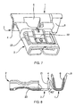
- the third mode of realization of the connector shown in Figures 7 and 8 distinguished by the shape of the wave and by the structure of the plug-in cage.
- Wave 4 has an edge on the side of the plug-in cage 2 21 inclined on the median plane of the cage 2.
- the inclination of the edge 21 is between 60 and 90 °; it is preferably around 80 ° approximately.
- the plug-in cage 2 has four connection blades electric, as in the embodiment of Figures 5 and 6, and it also has a tongue 22 of mechanical locking.
- This tab occupies the part axial of the bottom of the plug-in cage 2. It is articulated on the part of the plug-in cage adjacent to the transition 3, unlike the embodiment of Figures 1 to 4 where the tongue is articulated in the vicinity of opening of the plug-in cage 2.
- the cage 2 is fitted with lights such as 23 for facilitate its shaping from a cut sheet and folded.
- connection block 1 a been shown in Figures 1 to 6 with two wings of crimping 6 of the core of a cable, in the center of block 1, and on the right side, two fins 8 for holding the insulation, or cable sheath.
- connection block 1 can be provided with the fins crimping on the left. It can thus be provided with two crimping fins on the right and two others on the left, in the case where two cables must be crimped on the same connector. These two cables can have cores of different section, the two cores being crimped together by the crimping wings 6.
- the fins 8 for holding the insulation, or the sheath of the cables are shown to be symmetrical because the arrangement of the wave allows to take material between the block of connection 1 and the plug-in cage 2 to form a fin 8 long enough to be symmetrical to the other fin 8.
- this symmetrical arrangement of the fins 8 is not imperative and fins 8 can be asymmetrical.
- An objective of the invention is to reduce the distance between the connection block 1 and the plug-in cage 2 while keeping the same general contact plane in the cage plugging, and crimping, i.e. by keeping the direction of the plugging effort in the plane containing the axis of the conductor crimped in the crimping block.
- the shape of the wave is not limited to the examples described and represented in the figures and in particular in the figures 4 and 8, where the wave has only one alternation.
- the shape of the wave is likely to be different, for example with two half-waves.
- the wave can be inclined on the median plane of the insertion cage passing through the conductor's axis, as shown in the Figures 7 and 8.
Landscapes
- Connections Effected By Soldering, Adhesion, Or Permanent Deformation (AREA)
- Connector Housings Or Holding Contact Members (AREA)
Description
- les dimensions de la découpe centrale correspondent aux dimensions d'une pince à sertir, de manière à centrer les mâchoires de la pince à sertir lors du sertissage ;
- l'onde de la zone de transition est agencée pour que l'axe de sertissage soit situé sensiblement dans le plan médian de la cage d'enfichage ;
- l'onde de la zone de transition présente en section un bord sensiblement vertical du côté de la cage d'enfichage ;
- l'onde de la zone de transition présente en section, du côté du bloc de raccordement une courbe se rattachant tangentiellement au fond du canal de sertissage;
- l'onde de la zone de transition est raccordée au plancher de la cage d'enfichage et au moins à une paroi latérale de la cage d'enfichage ;
- la (ou les) zone(s) de raccordement de l'onde aux plancher et paroi(s) latérale(s) de la cage d'enfichage comporte(nt) au moins un bord relevé de raidissement ;
- l'onde est agencée pour que la cage d'enfichage et le bloc de raccordement soient sensiblement coplanaires ;
- l'onde est inclinée sur le plan médian de la cage d'enfichage.
- l'inclinaison est comprise entre 60 et 90° et de préférence d'environ 80°.
- La figure 1 représente schématiquement une vue en perspective et de dessus d'un connecteur selon l'invention.
- La figure 2 représente schématiquement une vue en perspective et de dessous du connecteur de la figure 1.
- La figure 3 représente schématiquement une vue de dessus, et en coupe longitudinale partielle selon la ligne III-III de la figure 4, du connecteur de la figure 1.
- La figure 4 représente schématiquement une vue en élévation latérale avec coupes partielles selon la ligne IV-IV de la figure 3 du connecteur de la figure 1.
- La figure 5 représente schématiquement une vue en perspective de dessus d'un autre mode de réalisation d'un connecteur selon l'invention.
- La figure 6 représente schématiquement une vue en perspective de dessous du connecteur de la figure 5.
- La figure 7 représente schématiquement une vue en perspective de dessous d'un troisième mode de réalisation d'un connecteur selon l'invention.
- La figure 8 représente schématiquement une vue en coupe longitudinale dans le plan de symétrie de la cage d'enfichage du connecteur de la figure 7.
Claims (11)
- Connecteur femelle à sertir, du type "clip drapeau", destiné à recevoir une languette mâle pour réaliser une connexion électrique, comportant un bloc de raccordement (1) s'étendant transversalement à la cage d'enfichage (2) et relié à celle-ci par une zone de transition (3), avec une découpe centrale (15) correspondant au moins partiellement à une aile (6) du bloc de raccordement (1), caractérisé en ce que la zone de transition (3) comporte une onde (4), le plancher de la cage d'enfichage (2) et le fond du bloc de raccordement (1) étant en substance dans un même plan.
- Connecteur selon la revendication 1, caractérisé en ce que les dimensions de la découpe centrale (15) correspondent aux dimensions d'une pince à sertir, de manière à centrer les mâchoires de la pince à sertir lors du sertissage.
- Connecteur selon la revendication 1 ou la revendication 2, caractérisé en ce que l'onde de la zone de transition (3) est agencée pour que l'axe de sertissage (14) soit situé sensiblement dans le plan médian (16) de la cage d'enfichage (2).
- Connecteur selon l'une quelconque des revendications 1 à 3, caractérisé en ce que l'onde (4) de la zone de transition (3) présente en section un bord sensiblement vertical (5) du côté de la cage d'enfichage (2).
- Connecteur selon l'une quelconque des revendications précédentes, caractérisé en ce que l'onde (4) de la zone de transition (3) présente en section, du côté du bloc de raccordement (1) une courbe (6a) se rattachant tangentiellement au fond (7) du canal de sertissage.
- Connecteur selon l'une quelconque des revendications précédentes, caractérisé en ce que l'onde (4) de la zone de transition (3) est raccordée au plancher (9) de la cage d'enfichage (2) et au moins à une paroi latérale (12) de la cage d'enfichage (2).
- Connecteur selon la revendication 6, caractérisé en ce que la(ou les) zone(s) de raccordement de l'onde (4) aux plancher (9) et paroi(s) latérale(s) (12) de la cage d'enfichage (2) comporte(nt) au moins un bord (13) relevé de raidissement.
- Connecteur selon l'une quelconque des revendications précédentes, caractérisé en ce que l'onde (4) est agencée pour que la cage d'enfichage (2) et le bloc de raccordement (1) soient sensiblement coplanaires.
- Connecteur selon l'une quelconque des revendications précédentes, caractérisé en ce que la cage d'enfichage (2) comporte quatre lames (17, 18, 19, 20) susceptibles de coopérer avec la languette mâle pour réaliser la connexion électrique.
- Connecteur selon la revendication 3, caractérisé en ce que l'onde est inclinée sur le plan médian de la cage d'enfichage.
- Connecteur selon la revendication 10, caractérisé en ce que l'inclinaison est comprise entre 60 et 90° et de préférence d'environ 80°.
Applications Claiming Priority (2)
| Application Number | Priority Date | Filing Date | Title |
|---|---|---|---|
| FR9609075A FR2751475B1 (fr) | 1996-07-19 | 1996-07-19 | Connecteur femelle a sertir |
| FR9609075 | 1996-07-19 |
Publications (2)
| Publication Number | Publication Date |
|---|---|
| EP0820120A1 EP0820120A1 (fr) | 1998-01-21 |
| EP0820120B1 true EP0820120B1 (fr) | 2002-10-23 |
Family
ID=9494241
Family Applications (1)
| Application Number | Title | Priority Date | Filing Date |
|---|---|---|---|
| EP19970401732 Expired - Lifetime EP0820120B1 (fr) | 1996-07-19 | 1997-07-18 | Connecteur femelle à sertir |
Country Status (4)
| Country | Link |
|---|---|
| EP (1) | EP0820120B1 (fr) |
| DE (1) | DE69716524T2 (fr) |
| ES (1) | ES2182006T3 (fr) |
| FR (1) | FR2751475B1 (fr) |
Cited By (1)
| Publication number | Priority date | Publication date | Assignee | Title |
|---|---|---|---|---|
| DE20207231U1 (de) * | 2002-05-07 | 2003-09-18 | Grote & Hartmann | Elektrisches Kontaktelement |
Families Citing this family (6)
| Publication number | Priority date | Publication date | Assignee | Title |
|---|---|---|---|---|
| DE19828985B4 (de) * | 1998-06-29 | 2008-01-24 | The Whitaker Corp., Wilmington | Elektrischer Buchsenkontakt |
| DE112008000656B4 (de) | 2007-03-29 | 2014-11-27 | Autonetworks Technologies, Ltd. | Verbinderanschluss und Verbinder mit diesem Verbinderanschluss |
| DE102007016070A1 (de) | 2007-04-03 | 2008-10-09 | Lear Corp., Southfield | Elektrische Anschlussanordnung und Verfahren zum Nutzen der elektrischen Anschlussanordnung |
| CN208111733U (zh) * | 2018-03-13 | 2018-11-16 | 泰科电子(上海)有限公司 | 连接端子 |
| CN208209061U (zh) * | 2018-03-13 | 2018-12-07 | 泰科电子(上海)有限公司 | 连接端子 |
| CN110233407B (zh) * | 2019-07-15 | 2024-04-09 | 东莞莱奥智能科技有限公司 | 一种双头端子插壳线材自动机的线材插壳机构 |
Family Cites Families (2)
| Publication number | Priority date | Publication date | Assignee | Title |
|---|---|---|---|---|
| US3430191A (en) * | 1967-07-17 | 1969-02-25 | Products Inc Van | Connector clip |
| US3771111A (en) * | 1972-06-12 | 1973-11-06 | Amp Inc | Flag type electrical terminal |
-
1996
- 1996-07-19 FR FR9609075A patent/FR2751475B1/fr not_active Expired - Fee Related
-
1997
- 1997-07-18 DE DE1997616524 patent/DE69716524T2/de not_active Expired - Fee Related
- 1997-07-18 EP EP19970401732 patent/EP0820120B1/fr not_active Expired - Lifetime
- 1997-07-18 ES ES97401732T patent/ES2182006T3/es not_active Expired - Lifetime
Cited By (1)
| Publication number | Priority date | Publication date | Assignee | Title |
|---|---|---|---|---|
| DE20207231U1 (de) * | 2002-05-07 | 2003-09-18 | Grote & Hartmann | Elektrisches Kontaktelement |
Also Published As
| Publication number | Publication date |
|---|---|
| DE69716524D1 (de) | 2002-11-28 |
| DE69716524T2 (de) | 2003-08-07 |
| FR2751475B1 (fr) | 1998-10-09 |
| ES2182006T3 (es) | 2003-03-01 |
| EP0820120A1 (fr) | 1998-01-21 |
| FR2751475A1 (fr) | 1998-01-23 |
Similar Documents
| Publication | Publication Date | Title |
|---|---|---|
| EP0310487B1 (fr) | Borne de contact électrique de type cage | |
| EP2308137B1 (fr) | Connecteur électrique femelle et connexion utilisant ce connecteur électrique femelle | |
| EP3208892A1 (fr) | Connecteur électrique comportant une pluralité de lamelles électriquement conductrices | |
| FR2893452B1 (fr) | Borne a sertir et circuit plat l'utilisant | |
| EP0684662B1 (fr) | Connecteur autodénudant | |
| EP0711097A2 (fr) | Elément de connextion électrique pour vitrage chauffant pour automobile | |
| EP0820120A1 (fr) | Connecteur femelle à sertir | |
| FR2490029A1 (fr) | Borne de jonction ou de connexion pour conducteurs electriques | |
| FR2507396A1 (fr) | Bloc connecteur electrique multiple a broches en fil isole | |
| EP0209452B1 (fr) | Connecteur polyvalent pour la connexion de différents types de câbles ou conducteurs électriques | |
| EP1174947A1 (fr) | Dispositif de connexion électrique | |
| EP1383211A1 (fr) | Procédé de sertissage d'un contact sur des brins d'un câble | |
| FR3029698A1 (fr) | Element de connexion electrique a percage de gaine isolante d'un fil electrique | |
| EP0637045B1 (fr) | Dispositif de connexion électrique, notamment pour le passage de courants forts | |
| EP0008984B1 (fr) | Dispositif étanche de raccordement pour conducteurs électriques | |
| FR2852744A1 (fr) | Connecteur autodenudant pour circuit a composants montes en surface. | |
| FR2749440A1 (fr) | Borne de contact electrique femelle de type a cage renforcee | |
| WO2018109402A1 (fr) | Element de connexion electrique muni d'un element de contact | |
| EP1148589B1 (fr) | Elément femelle de connexion et connecteur femelle comportant un tel élément de connexion | |
| FR2819348A1 (fr) | Connexion autodenudante a fente convergente | |
| FR2751793A1 (fr) | Borne electrique femelle d'une seule piece | |
| EP0635992B1 (fr) | Element chauffant | |
| EP0786159B1 (fr) | Borne electrique a lames de contact precontraintes | |
| EP1162690B1 (fr) | Dispositif de connexion autodénudante pour un conducteur électrique gainé | |
| FR2507393A1 (fr) | Borne de contact electrique pour branchement rapide d'un conducteur isole |
Legal Events
| Date | Code | Title | Description |
|---|---|---|---|
| PUAI | Public reference made under article 153(3) epc to a published international application that has entered the european phase |
Free format text: ORIGINAL CODE: 0009012 |
|
| AK | Designated contracting states |
Kind code of ref document: A1 Designated state(s): DE ES FR GB IT |
|
| 17P | Request for examination filed |
Effective date: 19980302 |
|
| AKX | Designation fees paid |
Free format text: DE ES FR GB IT |
|
| RBV | Designated contracting states (corrected) |
Designated state(s): DE ES FR GB IT |
|
| 17Q | First examination report despatched |
Effective date: 20000218 |
|
| GRAG | Despatch of communication of intention to grant |
Free format text: ORIGINAL CODE: EPIDOS AGRA |
|
| GRAG | Despatch of communication of intention to grant |
Free format text: ORIGINAL CODE: EPIDOS AGRA |
|
| GRAH | Despatch of communication of intention to grant a patent |
Free format text: ORIGINAL CODE: EPIDOS IGRA |
|
| GRAH | Despatch of communication of intention to grant a patent |
Free format text: ORIGINAL CODE: EPIDOS IGRA |
|
| GRAA | (expected) grant |
Free format text: ORIGINAL CODE: 0009210 |
|
| AK | Designated contracting states |
Kind code of ref document: B1 Designated state(s): DE ES FR GB IT |
|
| REG | Reference to a national code |
Ref country code: GB Ref legal event code: FG4D Free format text: NOT ENGLISH |
|
| RAP2 | Party data changed (patent owner data changed or rights of a patent transferred) |
Owner name: TYCO ELECTRONICS FRANCE SAS |
|
| REF | Corresponds to: |
Ref document number: 69716524 Country of ref document: DE Date of ref document: 20021128 |
|
| REG | Reference to a national code |
Ref country code: ES Ref legal event code: FG2A Ref document number: 2182006 Country of ref document: ES Kind code of ref document: T3 |
|
| GBT | Gb: translation of ep patent filed (gb section 77(6)(a)/1977) |
Effective date: 20030212 |
|
| PGFP | Annual fee paid to national office [announced via postgrant information from national office to epo] |
Ref country code: GB Payment date: 20030612 Year of fee payment: 7 |
|
| PGFP | Annual fee paid to national office [announced via postgrant information from national office to epo] |
Ref country code: ES Payment date: 20030721 Year of fee payment: 7 |
|
| PLBE | No opposition filed within time limit |
Free format text: ORIGINAL CODE: 0009261 |
|
| STAA | Information on the status of an ep patent application or granted ep patent |
Free format text: STATUS: NO OPPOSITION FILED WITHIN TIME LIMIT |
|
| 26N | No opposition filed |
Effective date: 20030724 |
|
| PG25 | Lapsed in a contracting state [announced via postgrant information from national office to epo] |
Ref country code: GB Free format text: LAPSE BECAUSE OF NON-PAYMENT OF DUE FEES Effective date: 20040718 |
|
| PG25 | Lapsed in a contracting state [announced via postgrant information from national office to epo] |
Ref country code: ES Free format text: LAPSE BECAUSE OF NON-PAYMENT OF DUE FEES Effective date: 20040719 |
|
| GBPC | Gb: european patent ceased through non-payment of renewal fee |
Effective date: 20040718 |
|
| PG25 | Lapsed in a contracting state [announced via postgrant information from national office to epo] |
Ref country code: IT Free format text: LAPSE BECAUSE OF NON-PAYMENT OF DUE FEES;WARNING: LAPSES OF ITALIAN PATENTS WITH EFFECTIVE DATE BEFORE 2007 MAY HAVE OCCURRED AT ANY TIME BEFORE 2007. THE CORRECT EFFECTIVE DATE MAY BE DIFFERENT FROM THE ONE RECORDED. Effective date: 20050718 |
|
| PGFP | Annual fee paid to national office [announced via postgrant information from national office to epo] |
Ref country code: DE Payment date: 20050831 Year of fee payment: 9 |
|
| REG | Reference to a national code |
Ref country code: ES Ref legal event code: FD2A Effective date: 20040719 |
|
| PG25 | Lapsed in a contracting state [announced via postgrant information from national office to epo] |
Ref country code: DE Free format text: LAPSE BECAUSE OF NON-PAYMENT OF DUE FEES Effective date: 20070201 |
|
| REG | Reference to a national code |
Ref country code: FR Ref legal event code: PLFP Year of fee payment: 20 |
|
| PGFP | Annual fee paid to national office [announced via postgrant information from national office to epo] |
Ref country code: FR Payment date: 20160726 Year of fee payment: 20 |