EP0819954A2 - Appareil d'entrée d'image à fibres optiques - Google Patents
Appareil d'entrée d'image à fibres optiques Download PDFInfo
- Publication number
- EP0819954A2 EP0819954A2 EP97305261A EP97305261A EP0819954A2 EP 0819954 A2 EP0819954 A2 EP 0819954A2 EP 97305261 A EP97305261 A EP 97305261A EP 97305261 A EP97305261 A EP 97305261A EP 0819954 A2 EP0819954 A2 EP 0819954A2
- Authority
- EP
- European Patent Office
- Prior art keywords
- entrance surface
- light
- input apparatus
- image input
- angle
- Prior art date
- Legal status (The legal status is an assumption and is not a legal conclusion. Google has not performed a legal analysis and makes no representation as to the accuracy of the status listed.)
- Granted
Links
Images


Classifications
-
- G—PHYSICS
- G02—OPTICS
- G02B—OPTICAL ELEMENTS, SYSTEMS OR APPARATUS
- G02B6/00—Light guides; Structural details of arrangements comprising light guides and other optical elements, e.g. couplings
- G02B6/04—Light guides; Structural details of arrangements comprising light guides and other optical elements, e.g. couplings formed by bundles of fibres
- G02B6/06—Light guides; Structural details of arrangements comprising light guides and other optical elements, e.g. couplings formed by bundles of fibres the relative position of the fibres being the same at both ends, e.g. for transporting images
- G02B6/08—Light guides; Structural details of arrangements comprising light guides and other optical elements, e.g. couplings formed by bundles of fibres the relative position of the fibres being the same at both ends, e.g. for transporting images with fibre bundle in form of plate
Definitions
- the present invention relates to an image input apparatus for obtaining an object image of a fingerprint, rubber stamp, or the like having irregularities (pits and projections).
- Such an image input apparatus for example, are apparatus (first conventional example) disclosed in U.S. Patent No. 4,932,776 and Japanese Patent Application Laid-Open No. 6-300930.
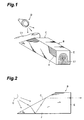
- an image input apparatus comprises a fiber optic plate (FOP) B in which a number of optical fibers A are bundled together and a light source (illuminating means) D for irradiating an entrance surface C of the fiber optic plate B, thereby outputting an image of a fingerprint or the like having irregularities.
- FOP fiber optic plate
- D light source
- the entrance surface C of the fiber optic plate B is inclined with respect to the optical axis (coinciding with the optical axis direction of each optical fiber therein) by a predetermined angle.
- a fiber optic plate (first conventional example) having the entrance surface C inclined with respect to the optical axis has been known as slant FOP, and its angle of inclination ⁇ 0 has been referred to as slant angle.
- the slant angle ⁇ 0 and the numerical aperture NA of the optical fibers A are matched with each other in order to prevent the unnecessary light (stray light) incident thereon from the part not in contact with the entrance surface C (depressed portion of the finger or the like not in contact with the entrance surface C) from propagating through the optical fibers A (from satisfying a total reflection condition).
- the above-mentioned unnecessary light is not theoretically outputted from the exit surface E.
- Japanese Patent Application Laid-Open No. 7-174947 discloses, as a fiber optic plate of a second conventional example, a structure in which an optical absorber is disposed between optical fibers constituting the fiber optic plate. As this optical absorber is disposed, light is prevented from traveling across the neighboring optical fibers, thereby the unnecessary light incident on the fiber optic plate from the part where the object C1 and the entrance surface C are not in contact with each other is efficiently attenuated in the fiber optic plate. Accordingly, in the fiber optic plate having such a structure, the contrast of the image outputted therefrom can be improved.
- the inventors have found the following problems. Namely, when light travels across the neighboring optical fibers in the fiber optic plate, the output image (image of the object having irregularities on its surface) may lower its contrast and become unclear. For example, even when the optical absorber is disposed between the neighboring optical fibers as in the case of the fiber optic plate disclosed in the above-mentioned Japanese Patent Application Laid-Open No. 7-174947, it is difficult for the optical absorber to completely absorb the light, and the light incident on one optical fiber from the part where the object is not in contact with the entrance surface may propagate to its neighboring optical fiber. Then, as shown in Fig.
- an object of the present invention is to provide an image input apparatus for obtaining a vivid image of an object having irregularities (pits and projections) on its surface.
- the image input apparatus comprises a specific structure for holding a light source at a predetermined position such that a luminous flux from the light source is made incident on the entrance surface of a fiber optic plate (hereinafter referred to as FOP) from a direction deviating from an angle region by which stray light can be incident on the entrance surface.
- FOP fiber optic plate
- the image input apparatus comprises a first FOP in which a plurality of optical fibers are bundled together; a housing for accommodating the first FOP; a plurality of light sources for illuminating the entrance surface of the first FOP; and a holding member having holding sections for holding the plurality of light sources such that the plurality of light sources surround at least a part of an opening of the housing.
- the first FOP has the entrance surface, which is inclined with respect to the optical axis of each optical fiber by a predetermined slant angle ⁇ 0 (0° ⁇ ⁇ 0 ⁇ 90°), and an exit surface opposing the entrance surface.
- the housing has an upper face bored with the opening for exposing the entrance surface.
- the holding sections of the holding member are disposed on the upper face of the housing and positioned so as to face each other across the opening of the housing.
- the holding member holds each light source in a state where, of incident angle components formed between the luminous flux emitted from the light source and the entrance surface, a vertical incident angle component ⁇ v on a plane orthogonal to a reference end on the entrance surface defining the slant angle ⁇ 0 is set to a range deviating from an angle region by which stray light can be incident on the entrance surface.
- an angle X by which the stray light can be incident on the entrance surface (hereinafter referred to as stray light admissible angle) is within the range given by the following expression: (X c - ⁇ ) ⁇ X ⁇ (X c + ⁇ )
- the holding member holds each light source in a state where the vertical incident angle component ⁇ v of the luminous flux from the light source is within the range of 0° to (X c - ⁇ ) or within the range of (X c + ⁇ ) to 180°.
- X c is a stray light admissible center angle given by an expression (90° - sin -1 (n core ⁇ sin(90°-3 ⁇ 0 ))); n core is a refractive index of a core in the optical fiber; ⁇ 0 is the slant angle; ⁇ is a total reflection critical angle in the air given by an expression (sin -1 (n core ⁇ sin(90° - S c - ⁇ ))); S c is a stray light admissible center angle in the optical fiber given by an expression (sin -1 ((1/n core ) ⁇ sin X c )); ⁇ is a total reflection critical angle in the optical fiber given by an expression (sin -1 (n clad /n core )); and n clad is a refractive index of a cladding in the optical fiber.
- the holding member may further comprise a structure for adjusting the divergent angle of the luminous flux emitted from the light source.
- the holding member may comprise a light-shielding member for covering, by way of an air gap, the entrance surface of the first FOP.
- the slant angle of the first FOP is within the range of 25° to 40°.
- the image input apparatus further comprises an image sensor having a light receiving surface positioned so as to face the exit surface of the first FOP, and can realize various kinds of structures.
- a second FOP may be disposed between the first FOP and the image sensor.
- the second FOP may be a taper FOP which tapers down in its cross-sectional area from the first FOP toward the image sensor.
- the exit surface and entrance surface of the first FOP may be in parallel to each other.
- an optical system may be disposed between the first FOP and the image sensor or between the second FOP and the image sensor.
- the holding structure it becomes easier to control the irradiating direction of the light source, while the luminous flux is restrained from being irradiated within the above-mentioned region of stray light admissible angle X.
- a desired light component can securely be outputted alone from the exit surface, thereby yielding a more vivid image (whose contrast is not lowered by stray light).
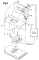
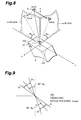
- Fig. 3 is a view in an assembling process for explaining a configuration of the image input apparatus according to the present invention.
- This image input apparatus according to the present invention comprises an FOP 2 (first FOP) in which a plurality of optical fibers are bundled together.
- This FOP 2 which has an entrance surface 22 inclined with respect to the optical axis of each optical fiber by a predetermined slant angle ⁇ 0 (0° ⁇ ⁇ 0 ⁇ 90°) and an exit surface 23 opposing the entrance surface 22, is accommodated in a housing 100.
- An image sensor (CCD) 6 is disposed on the exit surface 23 side of the FOP 2 and is supported by a pedestal 300 having an engagement depression 301 formed on a main surface thereof.
- the pedestal 300 engages with the housing 100, thereby constituting a dark room for accommodating the FOP 2. Further, the housing 100 has an upper face 150 bored with an opening 101 for exposing the entrance surface 22 of the FOP 2. Light sources (illuminating means) 3 for illuminating the entrance surface 22 of the FOP 2 are held at predetermined positions by a holding member 200.
- This holding member 200 comprises holding sections 250 and 260 disposed so as to face each other across the opening 101 of the housing 100. Each light source 3 is accommodated in a hole 201 formed in any of the holding sections 250 and 260.
- the image input apparatus further comprises a control system 400.
- the control system 400 receives an electric signal (video signal) from the image sensor 6, subjects thus received signal to a predetermined image processing, and controls driving of the light sources 3.
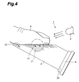
- Fig. 4 is a view showing a configuration of a main part of the image input apparatus according to the present invention.
- this image input apparatus 1 comprises, at least, the FOP 2 and, as a light source, an LED 3.
- the FOP 2 comprises a number of optical fibers 21 which are substantially oriented to the same direction and bundled together. Both end portions of the optical fibers 21 are respectively provided with the entrance surface 22 and the exit surface 23, thereby the light incident on the entrance surface 22 can be outputted from the exit surface 23.
- an optical absorber 24 be disposed between neighboring optical fibers 21 within the FOP 2.
- each optical fiber 21 is constituted by a core 21b having a predetermined refractive index n core and a cladding 21a, disposed around an outer periphery of the core 21b, having a refractive index n clad lower than n core .
- the entrance surface 22, used for making light incident on the optical fiber 21 by way of protruded portions of an object 4 in contact therewith, is inclined with respect to the optical axis direction of the optical fiber 21 by a predetermined angle (neither in parallel nor perpendicular thereto). It is preferred that the angle of inclination ⁇ 0 (slant angle) of the entrance surface 22 be set such that the unnecessary light incident thereon from depressed portions (noncontact portions) of the object 4 which are not in contact with the entrance surface 22 (reflected light from the depressed portions) does not propagate through the optical fiber 21.
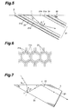
- a slant angle of the entrance surface 22 is determined according to the refractive indices of the cladding 21a and core 21b of the optical fiber 21 as shown in Fig. 5.
- n core ⁇ sin ⁇ n clad ⁇ sin 90° (condition for total reflection propagation)
- the slant angle ⁇ 0 is an angle at which the light incident on the entrance surface 22 substantially in parallel thereto propagates through the optical fiber 21 while being totally reflected by an angle close to its critical angle.
- this slant angle ⁇ 0 is made smaller than ⁇ M , no matter by which angle light is incident from the air, it is theoretically prevented from being reflected by an interface between the cladding 21a and core 21b and thereby propagating through the optical fiber 21.
- the slant angle ⁇ 0 can be set to an angle smaller than 36°, e.g., about 30°.
- the slant angle ⁇ 0 cannot be set independently of the material of the optical fiber 21 used since it depends on the refractive indices n clad and n core of the core 21b and cladding 21a of the optical fiber 21, it is typically set within the range of about 20° to 40°.
- the exit surface 23, which is an output surface for emitting the light propagating through the optical fiber 21 after being made incident on the entrance surface 22, is substantially orthogonal to the optical axis direction of the optical fiber 21 so that the light can easily be outputted from the optical fiber 21.
- the optical absorber 24 disposed between the optical fibers 21 in the FOP 2 it is, however, difficult for the optical absorber 24 disposed between the optical fibers 21 in the FOP 2 to completely prevent the light from traveling across the optical fibers 21.
- the incident light may be transmitted through the optical absorber 24 and guided to the neighboring optical fiber 21.
- the optical absorber 24, or a side face 25 of the FOP 2 light being reflected by the side face 25 in Fig. 7) and further reflected by the entrance surface 22 toward the inside of the FOP 2
- the light will propagate through the optical fiber 21 (will advance along the optical axis direction of the optical fiber 21) while being totally reflected, so as to be outputted from the exit surface 23.
- the LED 3 which is a light source, is held by the holding member 200 such that the light from the light source is incident on the entrance surface 22 of the FOP 2 within a range which deviates from a stray light admissible angle range (incident angle of stray light reachable to the exit surface 23).
- the LED 3 is means for irradiating the object 4 in contact with the entrance surface, e.g., a finger, with light having a predetermined wavelength, thereby effectively increasing the light quantity incident on the entrance surface 22 from the object 4 in contact therewith.
- the LED 3 preferably used is one which can emit light with a high directivity.
- LED 3 when such an LED 3 is used, it becomes easier to control the light irradiating direction (advancing direction of the luminous flux emitted from the light source), thereby preventing the light from being irradiated at a stray light admissible angle.
- other light emitters such as lasers and lamps may be used as the light source as long as they can irradiate light at an angle different from the stray light admissible angle.
- an optical system such as lens may be disposed between the light source and the entrance surface 22 so as to irradiate the entrance surface 22 with the collimated light.
- incident angle components of a luminous flux illuminating the entrance surface 22 of the FOP 2 are expressed as being divided into a vertical incident angle component ⁇ v and a horizontal incident angle component ⁇ H .
- the entrance surface 22 of the FOP 2 is a surface on an x-y plane, and a normal on the x-y plane is the z axis.
- the x axis is an axis on the x-y plane which is in parallel to each of a reference end 220 for defining the slant angle ⁇ 0 (acute angle) and an auxiliary end 230 opposing the reference end 220 across the entrance surface 22.
- the y axis is an axis on the x-y plane which is at least orthogonal to the reference end 220.
- the reference end 220 is a border line between the side face 25 and the entrance surface 22 which is a segment containing the slant angle ⁇ 0 (acute angle).
- the auxiliary end 230 is a border line between the side face 25 and the entrance surface 22 which is a segment opposing the reference end 220.
- the vertical incident angle component ⁇ v refers to, when an incident luminous flux directed toward the entrance surface 22 is projected onto the depicted y-z plane, an angle component (0° to 180°) formed between the incident luminous flux component on the y-z plane and the y axis.
- the horizontal incident angle component ⁇ H refers to, when the incident luminous flux directed toward the entrance surface 22 is projected onto the depicted x-z plane, an angle component (0° to 90°) formed between the incident luminous flux component on the x-z plane and the x axis.
- 0° refers to the reference end 220 side as viewed from the origin O on the entrance surface 22, whereas 180° refers to the reference end 230 side as viewed from the origin O.
- 0° indicates that it coincides with the x axis in Fig. 8
- 90° indicates that it coincides with the z axis.
- the stray light refers to unnecessary light which enters the FOP 2 from the entrance surface 22 and then is transmitted through the optical absorber 24 so as to propagate through the optical fiber 21 independently of its optical axis.
- the stray light admissible angle X is the incident angle of the unnecessary luminous flux incident on the entrance surface 22 (defined by an angle component on the y-z plane similar to the above-mentioned vertical incident angle component in which the slang angle side of the FOP 2 is set to 0°). As shown in Fig.
- the stray light admissible angle X is within the range given by the following expression (4): (X c - ⁇ ) ⁇ X ⁇ (X c + ⁇ ) wherein X c is a stray light admissible center angle given by an expression (90° - sin -1 (n core ⁇ sin(90° - 3 ⁇ 0 ))); n core is the refractive index of the core in the optical fiber; ⁇ 0 is the slant angle; ⁇ is a total reflection critical angle in the air given by an expression (sin -1 (n core ⁇ sin(90° - S c - ⁇ ))); S c is a stray light admissible center angle in the optical fiber given by an expression (sin -1
- the stray light admissible center angle X c is an angle component on the y-z plane corresponding to the vertical incident angle component of the luminous flux when the stray light finally becomes in parallel to the optical axis direction of the optical fiber 21.
- the possible range of the stray light admissible angle X by which the stray light is outputted from the exit surface 23 after propagating through the optical fiber 21 while being totally reflected thereby is an angle range obtained when the total reflection critical angle ⁇ is added to and subtracted from the stray light admissible center angle X c as shown in Fig. 9.
- the total reflection dritical angle refers to the minimal incident angle of the light from the core 21b to the cladding 21a when the light propagates through the optical fiber 21 while being totally reflected thereby. Accordingly, the stray light admissible angle is within the range from (X c - ⁇ ) to (X c + ⁇ ), which is represented by expression (4).
- ⁇ - refers to the total reflection critical angle ( ⁇ ) on the reference end 220 side from the stray light admissible center angle X c
- ⁇ + refers to the total reflection critical angle ( ⁇ ) on the auxiliary end 230 side from the stray light admissible center angle X c .
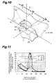
- the output light quantity from the exit surface 23 was measured. More specifically, in the respective states where the horizontal incident angle component ⁇ H was set to the predetermined angles (15°, 30°, and 90°), measurement was effected while the LED 3 was moved in the direction indicated by arrow L1 in Fig. 10 together with an optical system (lens) for collimating the output light from the LED 3.
- Fig. 11 is a graph showing the relationship between the vertical incident angle component ⁇ v and quantity of light outputted from the exit surface 23 measured by the method shown in Fig. 10.
- the ordinate indicates a normalized value in which the maximum output is taken as 100.
- the stray light admissible angle X is within the range of about 70° to 110° without considerably depending on the horizontal incident angle component ⁇ H . Namely, it can be seen that, when the light source 3 is disposed at a position where the luminous flux emitted from the light source 3 is incident on the entrance surface 22 such that its vertical incident angle component ⁇ v is on the outside of the above-mentioned range (70° to 110°), the stray light can be restrained from propagating through the FOP 2.
- the output light quantity from the exit surface 23 was measured. More specifically, in the state where the vertical incident angle component ⁇ v was set to a predetermined angle (90°), measurement was effected while the LED 3 was moved in the direction indicated by arrow L2 in Fig. 12 together with an optical system (lens) for collimating the output light from the LED 3.
- Fig. 13 is a graph showing the relationship between the horizontal incident angle component ⁇ H and quantity of light outputted from the exit surface 23 measured by the method shown in Fig. 12.
- the ordinate indicates a normalized value in which the maximum output is taken as 100.
- the horizontal incident angle component ⁇ H closer to 0° is more preferable, and it is preferably set to 20° or less.
- a light emitter having a directivity is preferably used as the light source 3
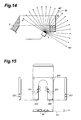
- a light source having a predetermined divergent angle about a center pencil 30 may also be utilized as shown in Fig. 14.
- the luminous flux from the light source 3 irradiates the entrance surface 22 with a certain extent of divergent angle.
- Such a divergent angle of the luminous flux emitted from the light source 3 can be regulated when the distance from an opening portion 202 of the fixing hole 201 formed in each of the holding sections 250 and 260 is adjusted as shown in Figs. 16 to 18.
- an optical system for example, lens
- a collimating means can be also provided at the opening portion 202.
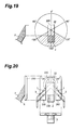
- the horizontal incident angle component ⁇ H of the luminous flux irradiating the entrance surface 22 is more preferable as it is closer to 0° as mentioned above, in the state where each light source is held by the holding section 200 (such that the center pencil 30 and the entrance surface 22 are in parallel to each other) as shown in Fig. 15, it is preferred that the luminous flux irradiate the entrance surface 22 from within the range of +120° to +180° or of -120° to -180° based on the segment connecting the origin O on the entrance surface 22 and the reference end 220 as shown in Fig. 19.
- the advancing direction of the center pencil 30 is within this range, of directional vector components of the center pencil 30, at least a component on the entrance surface 22 advances from the auxiliary end 230 toward the reference end 220.
- the holding member 200 holds each light source 3 at a position where the center pencil 30 from the light source 3 becomes in parallel to the entrance surface 22 while forming an angle of 125° with respect to an axis (coinciding with the y axis) on the entrance surface 22 perpendicular to the reference end 220 (see Fig. 20).
- the stray light is not limited to the unnecessary light from the light source 3. Accordingly, as shown in Fig. 21, when the holding member 200 is provided with a light-shielding member 270 for covering the entrance surface 22, the stray light can be more securely prevented from being made incident thereon (first application).
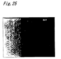
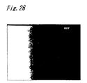
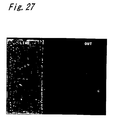
- Figs. 23 to 28 show photographs of the exit surface 23 of the FOP 2 represented on a display when the vertical incident angle component ⁇ v was actually changed.
- the slant angle ⁇ 0 of the FOP 2 used for photographing was 30°
- the horizontal incident angle component ⁇ H was 90°
- the light source 3 was moved in the direction of arrow L3 in Fig. 22, thereby the exit surface 23 (each photograph showing the exit surface 23 of the FOP 2 on the left side) was photographed in the respective cases where the vertical incident angle component ⁇ v was 0° (Fig. 23), 30° (Fig. 24), 60° (Fig. 25), 90° (Fig. 26), 120° (Fig. 27), and 150° (Fig. 28).
- the stray light can effectively be restrained from being incident when the vertical incident angle component ⁇ v is near 60° or at least 120°.
- the vertical incident angle component ⁇ v is 0° or 30°
- the stray light is not so effectively restrained from being incident.
- the vertical incident angle component ⁇ v is 90°
- the stray light is not prevented from being incident.
- the total reflection critical angle ⁇ in the air is about 20°.
- the FOP 2 has slant angles ⁇ 0 of 20° and 30°
- the entrance surface 22 is irradiated with the luminous flux from the LED 3 on the outside of thus given range of stray light admissible angle X, the stray light is not outputted from the entrance surface 23 of the FOP 2, and only the light incident on the entrance surface 22 from the portions in contact therewith is vividly outputted from the exit surface 23.
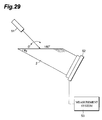
- the inventors measured characteristics of the incident angle component (vertical incident angle component ⁇ V ) and output intensity of stray light by using actual FOPs 2 and a measurement apparatus shown in Fig. 29.
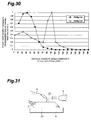
- Fig. 30 shows measured data obtained from the measurement apparatus shown in Fig. 29.
- the prepared FOPs 2 respectively have slant angles ⁇ 0 of 20° and 30°.
- the core refractive index n core is 1.50
- each FOP 2 in the state where the horizontal incident angle component ⁇ H was fixed to 90°, the change in output intensity of stray light emitted from the exit surface 23 was measured while the vertical incident angle component ⁇ v with respect to the entrance surface 22 was changed from 5° to 180° (the reference end side of the FOP 2 was assumed to be 0°).
- a semiconductor laser 51 LN9R manufactured by Matsushita Electric Industrial Co., Ltd; 35 mW, 680 nm
- a CCD 52 (BS7259 manufactured by Matsushita Electronics Industry Corp.) was attached to the exit surface 52, and its output was received by an output detecting apparatus (DVS3000 manufactured by Hamamatsu Photonics K.K.), thereby the stray light output intensity was measured by regional integration.
- the stray light output intensity is maximized at a vertical incident angle component ⁇ v of 30° and decreases as the vertical incident angle component ⁇ v increases and decreases from this angle. Further, in the FOP 2 having a slant angle of 30°, while the stray light output intensity is maximized at a vertical incident angle component ⁇ v of 90° and decreases as the vertical incident angle component ⁇ v increases and decreases from this angle, the output intensity tends to increase near an incident angle of 20° as well.
- the ordinate refers to a normalized value in which the maximum value of stray light output intensity is taken as 1.
- the stray light can be restrained from being outputted, thereby desired light can clearly be outputted alone.
- the LED 3 is disposed such that its luminous flux emitting surface is directed to the entrance surface 22 of the FOP 2, and the entrance surface 22 is irradiated with a luminous flux at an angle other than the stray light admissible angle X.
- the exit surface 23 of the FOP 2 is provided with a photoelectric conversion device 6 such as CCD such that an image of the light outputted from the exit surface 23 can be converted into an electric signal to be outputted therefrom.
- the finger 4 is irradiated with light from the LED 3, and this light is made incident on the optical fibers 21 by way of the protruded portions 41 of the fingerprint of the finger 4.
- the light from the LED 3 irradiates the entrance surface 22 with the angle other than the stray light admissible angle X, even if it is directly incident on the entrance surface 22 from the air not by way of the finger 4, it will not become stray light so as to be outputted from the exit surface 23.
- the light incident on the optical fibers 21 by way of the finger 4 propagates through each optical fiber 21 while being totally reflected thereby and reaches the exit surface 23, from which it is outputted as an image corresponding to the fingerprint (irregularity pattern) of the finger 4.
- the exit surface 23 since no stray light is incident on the entrance surface 22 from portions where the entrance surface 22 and the finger 4 are not in contact with each other, portions (depressed portions not in contact with the entrance surface 22) in the exit surface 23 other than the fingerprint image become dark, thereby yielding a clear fingerprint light image with a high contrast.
- the resulting clear image is fed into the photoelectric conversion device 6 so as to be processed as an electric signal.
- an object image can clearly be outputted according to the form of irregularities in contact with the entrance surface 22. Accordingly, it becomes quite useful when employed in an apparatus for identifying irregularity forms such as that used for detecting fingerprints.
- an image input apparatus la comprises, at least, the light source 3 and the FOP 2 having the entrance surface 22 and exit surface 23 in parallel to each other.
- the image input apparatus can be realized with various configurations as shown in Figs. 32 to 35.
- a third application shown in Fig. 32 is configured such that, between a slant FOP 500 having an entrance surface 501 and an image sensor 601, a taper FOP 600 which tapers down in its cross-sectional area from the slant FOP 500 toward the image sensor 601 is disposed. Also in this configuration, when the entrance surface 22 is irradiated with a luminous flux at an angle other than the above-mentioned stray light angle X, the stray light can effectively be restrained from propagating through the optical fiber.
- a fourth application shown in Fig. 33 comprises a slant FOP 510 having an entrance surface 511 and an exit surface 512 in parallel to each other; an image sensor 601; a slant FOP 510; and an optical system (lens) 602 disposed between the slant FOP 510 and the image sensor 601.
- the exit surface 512 of the slant FOP 510 has been subjected to scattering processing.
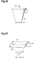
- a fifth application shown in Fig. 34 comprises a slant FOP 520 having an entrance surface 521 and an exit surface 522 in parallel to each other; an image sensor 601; and, as with the above-mentioned third application (Fig. 32), a taper FOP 600 disposed between the slant FOP 520 and the image sensor 601.
- a sixth application shown in Fig. 35 comprises a slant FOP 520 having an entrance surface 521 and an exit surface 522 in parallel to each other; an image sensor 601; a slant FOP 530, disposed between the slant FOP 520 and the image sensor 601, having an entrance surface 531 and an exit surface 532 in parallel to each other; and an optical system 602 disposed between the slant FOP 530 and the image sensor 601.
- the entrance surface 22 is irradiated with a luminous flux at an angle other than the above-mentioned stray light admissible angle X, the stray light can effectively be restrained from propagating through the optical fiber.
- the present invention as light for illuminating the entrance surface is emitted with an angle with respect to the entrance surface other than the stray light admissible angle, only light incident on the entrance surface from protruded portions of an object in contact with the entrance surface is outputted from the exit surface, whereas light incident on the entrance surface from depressed portions of the object not in contact with the entrance surface is not outputted from the exit surface. Accordingly, a clear object image corresponding to the irregularity pattern of the object surface can be obtained.
- the irradiating direction of the light from the light source (advancing direction of the luminous flux emitted from the light source) can easily be controlled, whereby the light can be restrained from being irradiated at the stray light admissible angle. Consequently, the desired light can securely be outputted alone from the exit surface.
Applications Claiming Priority (3)
| Application Number | Priority Date | Filing Date | Title |
|---|---|---|---|
| JP18514996 | 1996-07-15 | ||
| JP185149/96 | 1996-07-15 | ||
| JP18514996 | 1996-07-15 |
Publications (3)
| Publication Number | Publication Date |
|---|---|
| EP0819954A2 true EP0819954A2 (fr) | 1998-01-21 |
| EP0819954A3 EP0819954A3 (fr) | 1998-02-25 |
| EP0819954B1 EP0819954B1 (fr) | 2004-01-21 |
Family
ID=16165726
Family Applications (1)
| Application Number | Title | Priority Date | Filing Date |
|---|---|---|---|
| EP97305261A Expired - Lifetime EP0819954B1 (fr) | 1996-07-15 | 1997-07-15 | Appareil d'entrée d'image à fibres optiques |
Country Status (3)
| Country | Link |
|---|---|
| US (1) | US5875025A (fr) |
| EP (1) | EP0819954B1 (fr) |
| DE (1) | DE69727266T2 (fr) |
Cited By (3)
| Publication number | Priority date | Publication date | Assignee | Title |
|---|---|---|---|---|
| WO2001055763A2 (fr) * | 2000-01-26 | 2001-08-02 | N.V. Krypton Electronic Engineering | Element optique |
| WO2003032034A1 (fr) * | 2001-10-02 | 2003-04-17 | Matsushita Electric Industrial Co., Ltd. | Appareil detecteur d'image |
| WO2015093985A1 (fr) * | 2013-12-19 | 2015-06-25 | Ampho R & D Limited | Appareil de suivi de ligne |
Families Citing this family (9)
| Publication number | Priority date | Publication date | Assignee | Title |
|---|---|---|---|---|
| IT1299838B1 (it) * | 1998-02-12 | 2000-04-04 | Gd Spa | Dispositivo ottico di controllo di presenza. |
| US6381347B1 (en) * | 1998-11-12 | 2002-04-30 | Secugen | High contrast, low distortion optical acquistion system for image capturing |
| US6324020B1 (en) * | 1999-08-04 | 2001-11-27 | Secugen Corporation | Method and apparatus for reduction of trapezoidal distortion and improvement of image sharpness in an optical image capturing system |
| KR20020028754A (ko) * | 2001-05-04 | 2002-04-17 | 안준영 | 액정표시겸 지문입력 패널 |
| KR100432490B1 (ko) * | 2001-09-17 | 2004-05-22 | (주)니트 젠 | 광학식 지문취득 장치 |
| CN100341022C (zh) * | 2002-08-21 | 2007-10-03 | 赛寇根公司 | 具有改善成像表面的薄膜晶体管传感器 |
| JP4507806B2 (ja) * | 2004-10-01 | 2010-07-21 | 三菱電機株式会社 | 指紋画像撮像装置 |
| US20070098326A1 (en) * | 2005-11-01 | 2007-05-03 | Kuo Huei P | Light guide screen with louver device |
| US10049257B2 (en) * | 2015-07-09 | 2018-08-14 | Gingy Technology Inc. | Fingerprint identification module |
Citations (4)
| Publication number | Priority date | Publication date | Assignee | Title |
|---|---|---|---|---|
| EP0348182A2 (fr) * | 1988-06-23 | 1989-12-27 | Fujitsu Limited | Appareil de détection de données de surfaces inégales |
| EP0372748A2 (fr) * | 1988-11-25 | 1990-06-13 | Fujitsu Limited | Dispositif de détection d'empreintes digitales |
| US5426296A (en) * | 1993-02-17 | 1995-06-20 | Mitsubishi Denki Kabushiki Kaisha | Irregular pattern input device comprising an optical fiber bundle |
| JPH07174947A (ja) * | 1993-11-02 | 1995-07-14 | Hamamatsu Photonics Kk | ファイバー光学プレート |
Family Cites Families (3)
| Publication number | Priority date | Publication date | Assignee | Title |
|---|---|---|---|---|
| US3906520A (en) * | 1973-08-03 | 1975-09-16 | Optics Technology Inc | Apparatus for producing a high contrast visible image from an object |
| US4785171A (en) * | 1987-01-15 | 1988-11-15 | Fingerprint Technology, Inc. | Fingerprint acquisition system with a fiber optic block |
| US4932776A (en) * | 1987-11-05 | 1990-06-12 | Fingerprint Technology, Inc. | Fingerprint acquisition system |
-
1997
- 1997-07-14 US US08/891,838 patent/US5875025A/en not_active Expired - Lifetime
- 1997-07-15 DE DE69727266T patent/DE69727266T2/de not_active Expired - Lifetime
- 1997-07-15 EP EP97305261A patent/EP0819954B1/fr not_active Expired - Lifetime
Patent Citations (4)
| Publication number | Priority date | Publication date | Assignee | Title |
|---|---|---|---|---|
| EP0348182A2 (fr) * | 1988-06-23 | 1989-12-27 | Fujitsu Limited | Appareil de détection de données de surfaces inégales |
| EP0372748A2 (fr) * | 1988-11-25 | 1990-06-13 | Fujitsu Limited | Dispositif de détection d'empreintes digitales |
| US5426296A (en) * | 1993-02-17 | 1995-06-20 | Mitsubishi Denki Kabushiki Kaisha | Irregular pattern input device comprising an optical fiber bundle |
| JPH07174947A (ja) * | 1993-11-02 | 1995-07-14 | Hamamatsu Photonics Kk | ファイバー光学プレート |
Non-Patent Citations (1)
| Title |
|---|
| PATENT ABSTRACTS OF JAPAN vol. 095, no. 010, 30 November 1995 & JP 07 174947 A (HAMAMATSU PHOTONICS KK), 14 July 1995, * |
Cited By (6)
| Publication number | Priority date | Publication date | Assignee | Title |
|---|---|---|---|---|
| WO2001055763A2 (fr) * | 2000-01-26 | 2001-08-02 | N.V. Krypton Electronic Engineering | Element optique |
| BE1013248A3 (nl) * | 2000-01-26 | 2001-11-06 | Krypton Electronic Eng Nv | Optisch apparaat. |
| WO2001055763A3 (fr) * | 2000-01-26 | 2002-08-15 | Krypton Electronic Eng Nv | Element optique |
| US6804013B2 (en) | 2000-01-26 | 2004-10-12 | Krypton Electronic Engineering N.V. | Optical element |
| WO2003032034A1 (fr) * | 2001-10-02 | 2003-04-17 | Matsushita Electric Industrial Co., Ltd. | Appareil detecteur d'image |
| WO2015093985A1 (fr) * | 2013-12-19 | 2015-06-25 | Ampho R & D Limited | Appareil de suivi de ligne |
Also Published As
| Publication number | Publication date |
|---|---|
| EP0819954B1 (fr) | 2004-01-21 |
| DE69727266D1 (de) | 2004-02-26 |
| EP0819954A3 (fr) | 1998-02-25 |
| US5875025A (en) | 1999-02-23 |
| DE69727266T2 (de) | 2004-11-25 |
Similar Documents
| Publication | Publication Date | Title |
|---|---|---|
| US5426296A (en) | Irregular pattern input device comprising an optical fiber bundle | |
| US5684905A (en) | Fiber optic plate for making pattern image incident on photosensor | |
| EP0819954B1 (fr) | Appareil d'entrée d'image à fibres optiques | |
| JP4767964B2 (ja) | 画像読取装置 | |
| US9715053B2 (en) | Light guide, illuminating device and image reading apparatus | |
| US5684906A (en) | Fiber optical plate | |
| JPH09105625A (ja) | 距離測定装置 | |
| EP0821248B1 (fr) | Elément à fibre optique, élément photorécepteur, et dispositif d'acquisition de structure | |
| US8702280B2 (en) | Light source device | |
| US4560866A (en) | Image pick-up apparatus with folding optics | |
| JPS597926B2 (ja) | 位置検出装置 | |
| JP3110745B2 (ja) | 光学式原稿走査装置 | |
| JP3887465B2 (ja) | 画像入力装置 | |
| US5781269A (en) | Distance measuring method and distance sensor | |
| EP0846964B1 (fr) | Bloc en fibre optiques | |
| EP0899597B1 (fr) | Appareil à balayage des faisceaux lumineux | |
| DK241483A (da) | Apparat til at bestemme brydningsindeksprofilen for optiske fibre og forstadier til optiske fibre | |
| US6480303B1 (en) | Light amount distribution control device | |
| JP2000048616A (ja) | 導光体、照明装置及びそれを用いた画像読取装置 | |
| US5074668A (en) | Surface inspection apparatus | |
| JP2533118B2 (ja) | 光ファイバの外径測定方法 | |
| JPH0648323B2 (ja) | 光フアイバ軸ずれ測定方法 | |
| JP2021081251A (ja) | 測定装置 | |
| JPH10104444A (ja) | ファイバ光学デバイス、受光部品及びパターン取得装置 | |
| JP3415240B2 (ja) | 画像出力装置 |
Legal Events
| Date | Code | Title | Description |
|---|---|---|---|
| PUAI | Public reference made under article 153(3) epc to a published international application that has entered the european phase |
Free format text: ORIGINAL CODE: 0009012 |
|
| PUAL | Search report despatched |
Free format text: ORIGINAL CODE: 0009013 |
|
| AK | Designated contracting states |
Kind code of ref document: A2 Designated state(s): DE FR GB |
|
| AK | Designated contracting states |
Kind code of ref document: A3 Designated state(s): AT BE CH DE DK ES FI FR GB GR IE IT LI LU MC NL PT SE |
|
| 17P | Request for examination filed |
Effective date: 19980824 |
|
| AKX | Designation fees paid |
Free format text: DE FR GB |
|
| RBV | Designated contracting states (corrected) |
Designated state(s): DE FR GB |
|
| 17Q | First examination report despatched |
Effective date: 19981221 |
|
| GRAH | Despatch of communication of intention to grant a patent |
Free format text: ORIGINAL CODE: EPIDOS IGRA |
|
| GRAH | Despatch of communication of intention to grant a patent |
Free format text: ORIGINAL CODE: EPIDOS IGRA |
|
| GRAA | (expected) grant |
Free format text: ORIGINAL CODE: 0009210 |
|
| AK | Designated contracting states |
Kind code of ref document: B1 Designated state(s): DE FR GB |
|
| REG | Reference to a national code |
Ref country code: GB Ref legal event code: FG4D |
|
| REF | Corresponds to: |
Ref document number: 69727266 Country of ref document: DE Date of ref document: 20040226 Kind code of ref document: P |
|
| ET | Fr: translation filed | ||
| PLBE | No opposition filed within time limit |
Free format text: ORIGINAL CODE: 0009261 |
|
| STAA | Information on the status of an ep patent application or granted ep patent |
Free format text: STATUS: NO OPPOSITION FILED WITHIN TIME LIMIT |
|
| 26N | No opposition filed |
Effective date: 20041022 |
|
| REG | Reference to a national code |
Ref country code: FR Ref legal event code: PLFP Year of fee payment: 20 |
|
| PGFP | Annual fee paid to national office [announced via postgrant information from national office to epo] |
Ref country code: FR Payment date: 20160613 Year of fee payment: 20 |
|
| PGFP | Annual fee paid to national office [announced via postgrant information from national office to epo] |
Ref country code: GB Payment date: 20160713 Year of fee payment: 20 Ref country code: DE Payment date: 20160712 Year of fee payment: 20 |
|
| REG | Reference to a national code |
Ref country code: DE Ref legal event code: R071 Ref document number: 69727266 Country of ref document: DE |
|
| REG | Reference to a national code |
Ref country code: GB Ref legal event code: PE20 Expiry date: 20170714 |
|
| PG25 | Lapsed in a contracting state [announced via postgrant information from national office to epo] |
Ref country code: GB Free format text: LAPSE BECAUSE OF EXPIRATION OF PROTECTION Effective date: 20170714 |