EP0819582B1 - Gassack für ein Fahrzeuginsassen-Rückhaltesystem - Google Patents
Gassack für ein Fahrzeuginsassen-Rückhaltesystem Download PDFInfo
- Publication number
- EP0819582B1 EP0819582B1 EP97111534A EP97111534A EP0819582B1 EP 0819582 B1 EP0819582 B1 EP 0819582B1 EP 97111534 A EP97111534 A EP 97111534A EP 97111534 A EP97111534 A EP 97111534A EP 0819582 B1 EP0819582 B1 EP 0819582B1
- Authority
- EP
- European Patent Office
- Prior art keywords
- seam
- gas bag
- gas
- thread
- outflow
- Prior art date
- Legal status (The legal status is an assumption and is not a legal conclusion. Google has not performed a legal analysis and makes no representation as to the accuracy of the status listed.)
- Expired - Lifetime
Links
- 239000004744 fabric Substances 0.000 claims description 10
- 230000001143 conditioned effect Effects 0.000 claims 1
- 238000004519 manufacturing process Methods 0.000 description 3
- 230000015572 biosynthetic process Effects 0.000 description 2
Images

Classifications
-
- B—PERFORMING OPERATIONS; TRANSPORTING
- B60—VEHICLES IN GENERAL
- B60R—VEHICLES, VEHICLE FITTINGS, OR VEHICLE PARTS, NOT OTHERWISE PROVIDED FOR
- B60R21/00—Arrangements or fittings on vehicles for protecting or preventing injuries to occupants or pedestrians in case of accidents or other traffic risks
- B60R21/02—Occupant safety arrangements or fittings, e.g. crash pads
- B60R21/16—Inflatable occupant restraints or confinements designed to inflate upon impact or impending impact, e.g. air bags
- B60R21/23—Inflatable members
- B60R21/235—Inflatable members characterised by their material
-
- B—PERFORMING OPERATIONS; TRANSPORTING
- B60—VEHICLES IN GENERAL
- B60R—VEHICLES, VEHICLE FITTINGS, OR VEHICLE PARTS, NOT OTHERWISE PROVIDED FOR
- B60R21/00—Arrangements or fittings on vehicles for protecting or preventing injuries to occupants or pedestrians in case of accidents or other traffic risks
- B60R21/02—Occupant safety arrangements or fittings, e.g. crash pads
- B60R21/16—Inflatable occupant restraints or confinements designed to inflate upon impact or impending impact, e.g. air bags
- B60R21/23—Inflatable members
- B60R21/239—Inflatable members characterised by their venting means
-
- D—TEXTILES; PAPER
- D05—SEWING; EMBROIDERING; TUFTING
- D05B—SEWING
- D05B93/00—Stitches; Stitch seams
-
- B—PERFORMING OPERATIONS; TRANSPORTING
- B60—VEHICLES IN GENERAL
- B60R—VEHICLES, VEHICLE FITTINGS, OR VEHICLE PARTS, NOT OTHERWISE PROVIDED FOR
- B60R21/00—Arrangements or fittings on vehicles for protecting or preventing injuries to occupants or pedestrians in case of accidents or other traffic risks
- B60R21/02—Occupant safety arrangements or fittings, e.g. crash pads
- B60R21/16—Inflatable occupant restraints or confinements designed to inflate upon impact or impending impact, e.g. air bags
- B60R21/23—Inflatable members
- B60R21/235—Inflatable members characterised by their material
- B60R2021/23571—Inflatable members characterised by their material characterised by connections between panels
- B60R2021/23576—Sewing
Definitions
- the invention relates to an airbag for a vehicle occupant restraint system, which consists of at least one piece of fabric, the Edge at least along part of its length with a seam are connected.
- the invention relates to an airbag, at the outflow openings are provided, from which when the gas bag is deployed Part of the gas used to deploy the gas bag flow out can.
- the gas bag is tailored to the individual case Accident severity and the weight of the vehicle occupant, an optimal Restraint function achieved by the unfolded gas bag.
- the gas can flow out of the gas bag essentially to two The following can be achieved: On the one hand, in the wall of the gas bag Outflow openings are formed, which are either opened from the outset are or can be opened by the pressure inside the gas bag, and on the other hand, an outflow through gas-permeable areas of the Tissue itself can be achieved. Disadvantageous in the wall Outflow openings formed is the high manufacturing effort. Further can be used for outflow openings that are only above a certain one Pressure, certain fluctuations in the opening pressure are not avoid.
- the invention creates a gas bag in which minimal outflow openings are formed when the Airbag is in the unfolded state.
- the invention provided that between the two layers of fabric sewn together Outflow openings between the individual puncture points are provided by a in the unfolded state of the gas bag controlled outflow of gas takes place, the formation of the Outflow openings by adjusting the stitch length and the Tension of the thread of the seam is due.
- an inventive Airbag is therefore neither a separately designed outflow opening in a special gas-permeable fabric on the wall of the gas bag necessary to ensure a controlled outflow of gas from the deployed To achieve gas bag.
- the outlets are instead between the two layers of fabric sewn together in the area of the Seam formed, which is necessary to connect these layers of fabric anyway is.
- the stitch length of the seam is less than about 1 cm. At such a stitch length results in a good compromise between a sufficient strength of the seam and a large Total cross section of the outflow openings.
- FIGS. 1 and 2 schematically show an inventive one Airbag 5 shown, which is by means of a gas generator 7 with pressure can be applied and thereby unfolded.
- FIGS. 1 and 2 schematically show an inventive one Airbag 5 shown, which is by means of a gas generator 7 with pressure can be applied and thereby unfolded.
- FIGS. 1 and 2 schematically show an inventive one Airbag 5 shown, which is by means of a gas generator 7 with pressure can be applied and thereby unfolded.
- FIGS. 1 and 2 schematically show an inventive one Airbag 5 shown, which is by means of a gas generator 7 with pressure can be applied and thereby unfolded.
- FIGS. 1 and 2 schematically show an inventive one Airbag 5 shown, which is by means of a gas generator 7 with pressure can be applied and thereby unfolded.
- FIGS. 1 and 2 schematically show an inventive one Airbag 5 shown, which is by means of a gas generator 7 with pressure can be applied and thereby unfolded.
- FIGS. 1 left side are two
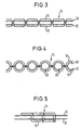
- the seam 14 consists of an upper thread 16 and a lower thread 18 ( Figures 3 and 4).
- the stitch length of the seam 14 and the tension of the Upper and lower thread 16, 18 are set so that at unfolded gas bag due to the prevailing in its interior Pressure between the puncture points of the seam 14 outflow openings 20 arise through which a part of itself in the interior of the gas bag located gas can flow out ( Figure 4).
- FIG. 2 shows the areas B in which the seam 14 is preferably used. These areas correspond to the Edge areas of the gas bag 10, which when the gas bag is unfolded be burdened comparatively low. It is also possible to sew the seam 14 to be used in the section lying between the regions B. In this case, it may be advantageous to use the stitch length in this Reduce section to increase the strength of the seam 14 achieve.
- FIG. 5 shows the seam 14 which, in contrast to that in FIG the variant shown in Figures 3 and 4 from a single thread 19th is formed.
- the seam can also change in the seam shown in FIG total outflow cross section resulting from pressurized seam the tension of the thread and the stitch length are influenced.
- the total cross section of the outflow openings 20 can in particular can be adjusted by the stitch length. With a shorter stitch length there is a smaller total outflow cross-section. Furthermore can the total outflow cross section through the tension of the thread or Upper and lower thread can be adjusted. One with a larger one Thread tension formed seam 14 leads to a smaller total outflow cross section. Overall, this results in comparison with conventional ones Gas bags a particularly cost-effective production, since neither special fabric for the gas bag still separate manufacturing steps are necessary for the formation of the outflow openings.
Landscapes
- Engineering & Computer Science (AREA)
- Mechanical Engineering (AREA)
- Textile Engineering (AREA)
- Air Bags (AREA)
Description
- Figur 1 einen schematischen Querschnitt durch einen erfindungsgemäßen Gassack;
- Figur 2 eine schematische Draufsicht auf den Gassack von Figur 1;
- Figur 3 schematisch und vergrößert einen Querschnitt durch eine bei dem in Figur 1 dargestellten Gassack verwendete Naht in einem drucklosen Zustand; und
- Figur 4 schematisch und vergrößert einen Querschnitt durch eine bei dem in Figur 1 dargestellten Gassack verwendete Naht in einem druckbeaufschlagten Zustand.
- Figur 5 schematisch und vergrößert einen Querschnitt durch eine bei dem in Figur 1 dargestellten Gassack verwendete andere Naht in einem drucklosen Zustand.
Claims (5)
- Gassack für ein Fahrzeuginsassen-Rückhaltesystem, der aus mindestens einem Gewebeteil besteht, dessen Ränder wenigstens entlang einem Teil ihrer Länge durch eine Naht (14) verbunden sind, dadurch gekennzeichnet, daß zwischen den beiden miteinander vernähten Gewebelagen (10, 12) jeweils zwischen den einzelnen Einstichstellen Ausströmöffnungen (20) vorgesehen sind, durch die im entfalteten Zustand des Gassacks (5) ein kontrolliertes Ausströmen von Gas erfolgt, wobei die Ausbildung der Ausströmöffnungen (20) durch die Einstellung der Stichlänge sowie der Spannung des Fadens der Naht (14) bedingt ist.
- Gassack nach Anspruch 1, dadurch gekennzeichnet, daß die Stichlänge der Naht (14) variabel ist.
- Gassack nach einem der vorhergehenden Ansprüche, dadurch gekennzeichnet, daß die Stichlänge der Naht (14) kleiner als etwa 1 cm ist.
- Gassack nach einem der vorhergehenden Ansprüche, dadurch gekennzeichnet, daß die Naht (14) aus einem Oberfaden (16) und einem Unterfaden (18) besteht.
- Gassack nach einem der Ansprüche 1 bis 3, dadurch gekennzeichnet, daß die Naht aus einem einzigen Faden (19) besteht.
Applications Claiming Priority (2)
| Application Number | Priority Date | Filing Date | Title |
|---|---|---|---|
| DE29612500U DE29612500U1 (de) | 1996-07-18 | 1996-07-18 | Gassack für ein Fahrzeuginsassen-Rückhaltesystem |
| DE29612500U | 1996-07-18 |
Publications (2)
| Publication Number | Publication Date |
|---|---|
| EP0819582A1 EP0819582A1 (de) | 1998-01-21 |
| EP0819582B1 true EP0819582B1 (de) | 2001-10-24 |
Family
ID=8026669
Family Applications (1)
| Application Number | Title | Priority Date | Filing Date |
|---|---|---|---|
| EP97111534A Expired - Lifetime EP0819582B1 (de) | 1996-07-18 | 1997-07-08 | Gassack für ein Fahrzeuginsassen-Rückhaltesystem |
Country Status (6)
| Country | Link |
|---|---|
| US (1) | US5899493A (de) |
| EP (1) | EP0819582B1 (de) |
| JP (1) | JPH1059105A (de) |
| KR (1) | KR980008860A (de) |
| DE (2) | DE29612500U1 (de) |
| ES (1) | ES2112233T3 (de) |
Families Citing this family (5)
| Publication number | Priority date | Publication date | Assignee | Title |
|---|---|---|---|---|
| DE29720461U1 (de) | 1997-11-19 | 1998-02-26 | Trw Automotive Safety Sys Gmbh | Gassack mit regelbarem Auslaßquerschnitt |
| DE19858690A1 (de) * | 1998-12-18 | 2000-06-21 | Delphi Automotive Systems Gmbh | Luftsack |
| DE19859767B4 (de) * | 1998-12-23 | 2005-09-29 | Autoliv Development Ab | Gassack mit Abströmöffnung |
| DE19903361A1 (de) * | 1999-01-28 | 2000-08-03 | Breed Automotive Tech | Verfahren zur Herstellung eines Luftsackes und Luftsack |
| DE102009005696A1 (de) * | 2009-01-19 | 2009-10-08 | Takata-Petri Ag | Fahrzeuginsassen-Rückhaltesystem mit einem aufblasbaren Gassack |
Family Cites Families (4)
| Publication number | Priority date | Publication date | Assignee | Title |
|---|---|---|---|---|
| GB1473794A (en) * | 1975-04-18 | 1977-05-18 | Nissan Motor | Inflatable and semi-crushable safety bag for vehicle passenger |
| US3990726A (en) * | 1975-04-23 | 1976-11-09 | Nissan Motor Co., Ltd. | Inflatable and semi-crushable safety bag for vehicle passenger |
| JPH0644759Y2 (ja) * | 1986-08-26 | 1994-11-16 | タカタ株式会社 | エアバッグの圧力調節装置 |
| JPH06104438B2 (ja) * | 1989-11-16 | 1994-12-21 | 池田物産株式会社 | エアバッグ装置 |
-
1996
- 1996-07-18 DE DE29612500U patent/DE29612500U1/de not_active Expired - Lifetime
-
1997
- 1997-07-08 ES ES97111534T patent/ES2112233T3/es not_active Expired - Lifetime
- 1997-07-08 EP EP97111534A patent/EP0819582B1/de not_active Expired - Lifetime
- 1997-07-08 DE DE59705040T patent/DE59705040D1/de not_active Expired - Fee Related
- 1997-07-14 US US08/892,383 patent/US5899493A/en not_active Expired - Fee Related
- 1997-07-16 KR KR1019970032978A patent/KR980008860A/ko not_active Withdrawn
- 1997-07-17 JP JP9192688A patent/JPH1059105A/ja active Pending
Also Published As
| Publication number | Publication date |
|---|---|
| ES2112233T1 (es) | 1998-04-01 |
| US5899493A (en) | 1999-05-04 |
| EP0819582A1 (de) | 1998-01-21 |
| JPH1059105A (ja) | 1998-03-03 |
| DE59705040D1 (de) | 2001-11-29 |
| KR980008860A (ko) | 1998-04-30 |
| ES2112233T3 (es) | 2002-05-16 |
| DE29612500U1 (de) | 1996-11-14 |
Similar Documents
| Publication | Publication Date | Title |
|---|---|---|
| DE69509938T2 (de) | Verfahren und Vorrichtung zum Rückhalten eines Fahrzeuginsassens | |
| EP1095815B1 (de) | Fahrzeugsitz für ein Kraftfahrzeug mit einer Rückenlehne | |
| DE69828681T2 (de) | Airbag vorrichtung für seitenaufprall bei fahrzeugen | |
| DE69406007T2 (de) | Luftsack mit aufblasbegrenzer | |
| EP0495409B1 (de) | Aufblasbarer Gassack für Rückhaltesysteme in Fahrzeugen | |
| DE60117334T2 (de) | Gassack | |
| DE69300153T2 (de) | Führungskanal aus Gewebe für einen Airbag in Fahrzeugen. | |
| DE69625324T2 (de) | Sitzstruktur mit Seitenaufprall-Luftsackvorrichtung | |
| EP0590518B1 (de) | Aufblasbarer Seitenaufprall-Gassack für ein Rückhaltesystem in Fahrzeugen | |
| DE102018104392A1 (de) | Gassackmodul sowie Fahrzeuginsassen-Rückhaltesystem | |
| DE69822899T2 (de) | Aufblasbare Sicherheitsgurtvorrichtung | |
| DE202007006023U1 (de) | Gassackanordnung für ein Fahrzeuginsassen-Rückhaltesystem | |
| DE19939339A1 (de) | Gassack | |
| DE102009019930A1 (de) | Gassackmodul zum Schutz des Thorax- und Kopfbereichs eines Fahrzeuginsassen | |
| DE4116162A1 (de) | Sicherheitsgurt fuer fahrzeugsitze, insbesondere kraftfahrzeugsitze | |
| DE102004006185A1 (de) | Gassack zum Einbau in ein Kraftfahrzeug | |
| DE60124362T2 (de) | Airbagvorrichtung für ein Kraftfahrzeug | |
| DE102007013106A1 (de) | Fahrzeugsitzanordnung und Verfahren zum Schützen eines Fahrezuginsassen | |
| WO2020002287A1 (de) | Gassack für ein fahrzeugsicherheitssystem eines kraftfahrzeugs und gassackbaugruppe | |
| DE102010045969A1 (de) | Fahrzeugsitz mit einem Airbag | |
| EP1848615B1 (de) | Airbag sowie verfahren zum herstellen eines airbags | |
| WO2012062289A2 (de) | Knieairbaganordnung für fahrzeuge | |
| DE102004051663A1 (de) | Schaumkörper zur Herstellung eines Fahrzeugsitzes mit Airbagmodul | |
| DE19857517C2 (de) | Verfahren zum Herstellen eines Gurtbandes und danach hergestelltes Gurtband | |
| EP0819582A1 (de) | Gassack für ein Fahrzeuginsassen-Rückhaltesystem |
Legal Events
| Date | Code | Title | Description |
|---|---|---|---|
| PUAI | Public reference made under article 153(3) epc to a published international application that has entered the european phase |
Free format text: ORIGINAL CODE: 0009012 |
|
| AK | Designated contracting states |
Kind code of ref document: A1 Designated state(s): DE ES FR GB IT |
|
| AX | Request for extension of the european patent |
Free format text: AL;LT;LV;RO;SI |
|
| ITCL | It: translation for ep claims filed |
Representative=s name: DR. ING. A. RACHELI & C. |
|
| GBC | Gb: translation of claims filed (gb section 78(7)/1977) | ||
| REG | Reference to a national code |
Ref country code: ES Ref legal event code: BA2A Ref document number: 2112233 Country of ref document: ES Kind code of ref document: T1 |
|
| EL | Fr: translation of claims filed | ||
| 17P | Request for examination filed |
Effective date: 19980313 |
|
| RAP1 | Party data changed (applicant data changed or rights of an application transferred) |
Owner name: TRW OCCUPANT RESTRAINT SYSTEMS GMBH & CO. KG |
|
| AKX | Designation fees paid |
Free format text: DE ES FR GB IT |
|
| RBV | Designated contracting states (corrected) |
Designated state(s): DE ES FR GB IT |
|
| 17Q | First examination report despatched |
Effective date: 20000714 |
|
| GRAG | Despatch of communication of intention to grant |
Free format text: ORIGINAL CODE: EPIDOS AGRA |
|
| GRAG | Despatch of communication of intention to grant |
Free format text: ORIGINAL CODE: EPIDOS AGRA |
|
| GRAH | Despatch of communication of intention to grant a patent |
Free format text: ORIGINAL CODE: EPIDOS IGRA |
|
| GRAH | Despatch of communication of intention to grant a patent |
Free format text: ORIGINAL CODE: EPIDOS IGRA |
|
| GRAA | (expected) grant |
Free format text: ORIGINAL CODE: 0009210 |
|
| AK | Designated contracting states |
Kind code of ref document: B1 Designated state(s): DE ES FR GB IT |
|
| REF | Corresponds to: |
Ref document number: 59705040 Country of ref document: DE Date of ref document: 20011129 |
|
| REG | Reference to a national code |
Ref country code: GB Ref legal event code: IF02 |
|
| GBT | Gb: translation of ep patent filed (gb section 77(6)(a)/1977) |
Effective date: 20020105 |
|
| ET | Fr: translation filed | ||
| REG | Reference to a national code |
Ref country code: ES Ref legal event code: FG2A Ref document number: 2112233 Country of ref document: ES Kind code of ref document: T3 |
|
| PGFP | Annual fee paid to national office [announced via postgrant information from national office to epo] |
Ref country code: GB Payment date: 20020613 Year of fee payment: 6 |
|
| PLBE | No opposition filed within time limit |
Free format text: ORIGINAL CODE: 0009261 |
|
| STAA | Information on the status of an ep patent application or granted ep patent |
Free format text: STATUS: NO OPPOSITION FILED WITHIN TIME LIMIT |
|
| 26N | No opposition filed | ||
| PGFP | Annual fee paid to national office [announced via postgrant information from national office to epo] |
Ref country code: FR Payment date: 20030702 Year of fee payment: 7 |
|
| PG25 | Lapsed in a contracting state [announced via postgrant information from national office to epo] |
Ref country code: GB Free format text: LAPSE BECAUSE OF NON-PAYMENT OF DUE FEES Effective date: 20030708 |
|
| PGFP | Annual fee paid to national office [announced via postgrant information from national office to epo] |
Ref country code: ES Payment date: 20030723 Year of fee payment: 7 |
|
| GBPC | Gb: european patent ceased through non-payment of renewal fee |
Effective date: 20030708 |
|
| PG25 | Lapsed in a contracting state [announced via postgrant information from national office to epo] |
Ref country code: ES Free format text: LAPSE BECAUSE OF NON-PAYMENT OF DUE FEES Effective date: 20040709 |
|
| PG25 | Lapsed in a contracting state [announced via postgrant information from national office to epo] |
Ref country code: FR Free format text: LAPSE BECAUSE OF NON-PAYMENT OF DUE FEES Effective date: 20050331 |
|
| REG | Reference to a national code |
Ref country code: FR Ref legal event code: ST |
|
| PG25 | Lapsed in a contracting state [announced via postgrant information from national office to epo] |
Ref country code: IT Free format text: LAPSE BECAUSE OF NON-PAYMENT OF DUE FEES Effective date: 20050708 |
|
| PGFP | Annual fee paid to national office [announced via postgrant information from national office to epo] |
Ref country code: DE Payment date: 20050729 Year of fee payment: 9 |
|
| REG | Reference to a national code |
Ref country code: ES Ref legal event code: FD2A Effective date: 20040709 |
|
| PG25 | Lapsed in a contracting state [announced via postgrant information from national office to epo] |
Ref country code: DE Free format text: LAPSE BECAUSE OF NON-PAYMENT OF DUE FEES Effective date: 20070201 |