EP0818643B1 - Split-torque hydromechanical transmission - Google Patents
Split-torque hydromechanical transmission Download PDFInfo
- Publication number
- EP0818643B1 EP0818643B1 EP97110718A EP97110718A EP0818643B1 EP 0818643 B1 EP0818643 B1 EP 0818643B1 EP 97110718 A EP97110718 A EP 97110718A EP 97110718 A EP97110718 A EP 97110718A EP 0818643 B1 EP0818643 B1 EP 0818643B1
- Authority
- EP
- European Patent Office
- Prior art keywords
- gear
- transmission according
- load shift
- shaft
- shift transmission
- Prior art date
- Legal status (The legal status is an assumption and is not a legal conclusion. Google has not performed a legal analysis and makes no representation as to the accuracy of the status listed.)
- Expired - Lifetime
Links
Images

Classifications
-
- F—MECHANICAL ENGINEERING; LIGHTING; HEATING; WEAPONS; BLASTING
- F16—ENGINEERING ELEMENTS AND UNITS; GENERAL MEASURES FOR PRODUCING AND MAINTAINING EFFECTIVE FUNCTIONING OF MACHINES OR INSTALLATIONS; THERMAL INSULATION IN GENERAL
- F16H—GEARING
- F16H47/00—Combinations of mechanical gearing with fluid clutches or fluid gearing
- F16H47/02—Combinations of mechanical gearing with fluid clutches or fluid gearing the fluid gearing being of the volumetric type
- F16H47/04—Combinations of mechanical gearing with fluid clutches or fluid gearing the fluid gearing being of the volumetric type the mechanical gearing being of the type with members having orbital motion
-
- F—MECHANICAL ENGINEERING; LIGHTING; HEATING; WEAPONS; BLASTING
- F16—ENGINEERING ELEMENTS AND UNITS; GENERAL MEASURES FOR PRODUCING AND MAINTAINING EFFECTIVE FUNCTIONING OF MACHINES OR INSTALLATIONS; THERMAL INSULATION IN GENERAL
- F16H—GEARING
- F16H37/00—Combinations of mechanical gearings, not provided for in groups F16H1/00 - F16H35/00
- F16H37/02—Combinations of mechanical gearings, not provided for in groups F16H1/00 - F16H35/00 comprising essentially only toothed or friction gearings
- F16H37/06—Combinations of mechanical gearings, not provided for in groups F16H1/00 - F16H35/00 comprising essentially only toothed or friction gearings with a plurality of driving or driven shafts; with arrangements for dividing torque between two or more intermediate shafts
- F16H37/08—Combinations of mechanical gearings, not provided for in groups F16H1/00 - F16H35/00 comprising essentially only toothed or friction gearings with a plurality of driving or driven shafts; with arrangements for dividing torque between two or more intermediate shafts with differential gearing
- F16H37/0833—Combinations of mechanical gearings, not provided for in groups F16H1/00 - F16H35/00 comprising essentially only toothed or friction gearings with a plurality of driving or driven shafts; with arrangements for dividing torque between two or more intermediate shafts with differential gearing with arrangements for dividing torque between two or more intermediate shafts, i.e. with two or more internal power paths
- F16H37/084—Combinations of mechanical gearings, not provided for in groups F16H1/00 - F16H35/00 comprising essentially only toothed or friction gearings with a plurality of driving or driven shafts; with arrangements for dividing torque between two or more intermediate shafts with differential gearing with arrangements for dividing torque between two or more intermediate shafts, i.e. with two or more internal power paths at least one power path being a continuously variable transmission, i.e. CVT
- F16H2037/088—Power split variators with summing differentials, with the input of the CVT connected or connectable to the input shaft
- F16H2037/0886—Power split variators with summing differentials, with the input of the CVT connected or connectable to the input shaft with switching means, e.g. to change ranges
Definitions
- the invention relates to a continuously variable hydrostatic-mechanical power-split power shift transmission according to the characteristics of the generic term of Claim 1 as known from EP-A-528 319. Such a transmission is used in work machines and vehicles.
- Another gear is known for example from DE 43 23 358.
- a Gearbox shown in the form of a 5-shaft epicyclic gearbox with three planetary gears, in which the starting gear is hydrostatic-mechanical power split.
- the adjustment unit When reversing, i.e. switching from forward to reverse gear or vice versa, the adjustment unit must be moved to the opposite extreme position when stationary, which causes a clearly perceptible delay in the reversing process.
- EP 0 716 248 shows a solution for how the switching time accelerates when reversing could be.
- the solution shown there grinds Starting or driving at low speeds the starting plate clutch what with work machines that have to start more often and often only with move at low speed, to a rapid wear of the multi-plate clutch can lead.
- a multi-plate clutch causes comparatively high idling losses. This problem arises in the same way in other embodiments.
- the extended input shaft can, for example used as an PTO in an agricultural tractor.
- About a common one Gearwheel arranged on the input side of the gearbox can simultaneously control the hydrostatic Actuator as well as the mechanical input shaft of the planetary gear become.
- the oil supply to the hydrostatic system and the lubrication of the transmission can be done easily with an oil pump driven by a shaft of the transmission.
- the Standard translation of the planetary gear set "0" is preferably selected so that at one determined speed from the the mechanical power share in the planetary gear transmitting shaft and an oppositely equal speed of the hydrostatic Power share in the planetary gear shaft the speed of the Starting shaft becomes 0.
- the gear steps should also be selected so that to achieve Equal speed swings at the switching points of the hydrostat nominally about 80% must become. Further advantageous configurations result from the features of Subclaims and the following physical description.
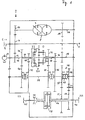
- a built-in gear 2 can be seen, which has no load-bearing functions in a vehicle can be installed.
- the driving force of an engine is from a transmission input shaft 4 in the Transfer gear 2.
- the input shaft 4 has an extension 5, the PTO can serve to drive downstream machines.
- the branches in the transmission on the gear 6 driving force via the hydrostatic actuator 8 drive-connected gear 10 in a hydrostatic and via the gear 12 in one mechanical power share.
- the arrow 9 symbolizes in the hydrostatic actuating gear 8 a pivoting position of the hydrostat.
- hydrostatic actuator 8 about the hydrostatic power share transmitting output shaft 14 and the gear 16 connected to it in a rotationally fixed manner hydrostatic actuator 8 in constant operative connection with the sun gear shaft 18 of the Planetary gear 20, here consisting of the planetary gear sets 0, I and II.
- the mechanical Power share is in the planetary gear via the step shaft II or ring gear shaft 22 20 introduced.
- the oil pump 13 is drive-connected to the shaft 22.
- the Output from the planetary gear 20 takes place via the non-rotatably connected to the ring gear shaft 24 Gears 26 and 28, via the gear 32 non-rotatably connected to the web 30 and via the gear 36 connected to the sun gear shaft 34 in a rotationally fixed manner.
- the gear wheels 26, 28, 32 and 36 are rotatable on a coupling shaft (Reverse gear input shaft 38 stored gears 40, 42, 44 and 46 of a 4-speed manual transmission in operative connection.
- the drive forces can be switched through to the clutch shaft 38 become.
- the couplings of the transmission 2 can be non-positive or positive Clutches be formed.
- a Reverse gear 48 arranged in which by actuating the clutch 50 between forward and Reverse gear can be switched back and forth.
- the steps 47/52 and 49/54 with intermediate gear 51 should have the same or similar translation. If full reversibility is not desired, You can of course choose translations that differ significantly from each other.
- the driving force is applied to the gear wheels 52 or 54 steered, which are non-rotatably mounted on the hollow shaft 56 and the drive energy via the Longitudinal differential gear 58 on the rear axle shaft 60 to the rear axle HA and the front axle shaft 62 transmits to the front axle VA of a vehicle.
- the longitudinal differential can in shown example can be optionally locked by a clutch K8. Instead of The longitudinal differential can be a smooth shaft, the front and rear axles rotatably with each other connects, used.
- the hydrostatic adjustment gear 8 is no longer pivoted into another extreme position are, it is sufficient in the regulated standstill of the coupling shaft 38, the coupling sleeve Coupling 50 from one position KV or KR to the other position KV or KR move what is possible in fractions of a second.
- a switchover can do so quickly that they are for the operator of the vehicle in which the transmission 2 located, can no longer be perceived as a time delay.
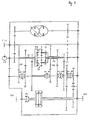
- Figure 2 shows a modification of the proposed transmission.
- the construction shown in Figure 2 is comparable to that of Figure 1; the essential difference is that on the shaft 24 and on the shaft 34 each additional gear 64, 66 attached and an additional double clutch is provided, whereby instead of the 4-speed manual transmission shown in Figure 1, a 6-speed manual transmission results.
- the output speed of the sun gear shaft 18 is shown on the abscissa and the achievable speed in km / h is shown on the ordinate.
- V forwards
- R backwards
- the driving force is coupled from the clutch 50 to the forward or reverse gear group.
- the vehicle equipped with the transmission according to the invention picks up speed by pivoting the hydrostratic actuating gear 8 in the + direction in the first driving range, which extends up to a speed of 3.5 km / h.
- the adjustment unit is swiveled fully back and the next higher gear must be engaged if the acceleration is to be continued. In the end, the shown top speed of 45 km / h can be reached. If a reduction in speed is desired, the gearbox is regulated in the opposite direction along the characteristic curve shown. Other speed values result when a different transmission ratio is selected and / or the individual sentences of the planetary gear 20 are assigned to one another in different ways. A person skilled in the art can easily adapt the proposed concept to the general conditions of a particular use.
- the characteristic curve shown in FIG. 3 for a 6-speed transmission can of course be varied and designed for other numbers of gears according to the requirements.
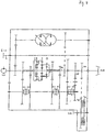
- FIG. 4 shows a transmission according to the invention as a so-called block construction transmission.
- Block gearboxes can have the gearbox arranged between the motor and axle supporting properties take.
- This transmission is also still in its structure and function comparable to the transmission shown in Figure 1. Differences arise here by the output shaft 68 is attached to the rear axle on the sun gear shaft 18, so that it have the same turning center and thus enables a flatter construction of the gear.
- the usual center distances between the input shaft are 4 and output shaft 68 possible, as they are from different tractor manufacturers be specified.
- the drive to the front axle is via any gear stage derived from the output shaft 68 and is or via a multi-plate clutch 70 switched off.
- the front axle speeds VA can be adjusted via level 71/72.
Description
Die Erfindung betrifft ein stufenloses hydrostatisch-mechanisch leistungsverzweigtes Lastschaltgetriebe
gemäß den Merkmalen des oberbegriffs von
Anspruch 1, wie es aus der EP-A-528 319 bekannt.
Ein solches Getriebe findet in Arbeitsmaschinen und Fahrzeugen Verwendung.The invention relates to a continuously variable hydrostatic-mechanical power-split power shift transmission
according to the characteristics of the generic term of
Ein weiteres Getriebe ist beispielsweise aus der DE 43 23 358 bekannt. Dort ist ein Getriebe in Form eines 5-welligen Umlaufgetriebes mit drei Planetensätzen gezeigt, in dem der Anfahrgang hydrostatisch-mechanisch leistungsverzweigt ist. Beim Reversieren, also Umschalten vom Vorwärts- in den Rückwärtsgang oder andersherum, muß die Verstelleinheit im Stillstand in die entgegengesetzte Extremlage verstellt werden, wodurch eine deutlich wahrnehmbare Verzögerung des Reversiervorgangs eintritt. In der EP 0 716 248 ist eine Lösung gezeigt, wie die Schaltzeit beim Reversieren beschleunigt werden könnte. Bei der dort gezeigten Lösung schleift beim Anfahren oder Fahren mit niedrigen Geschwindigkeiten die Anfahrlamellenkupplung, was bei Arbeitsmaschinen, die häufiger Anfahren müssen und sich auch häufig mit nur geringer Geschwindigkeit bewegen, zu einem schnellen Verschleiß der Lammellenkupplung führen kann. Außerdem verursacht eine Lamellenkupplung vergleichsweise hohe Leerlaufverluste. Dieses Problem stellt sich in gleicher Weise bei anderen Ausführungsformen.Another gear is known for example from DE 43 23 358. There is a Gearbox shown in the form of a 5-shaft epicyclic gearbox with three planetary gears, in which the starting gear is hydrostatic-mechanical power split. When reversing, i.e. switching from forward to reverse gear or vice versa, the adjustment unit must be moved to the opposite extreme position when stationary, which causes a clearly perceptible delay in the reversing process. In EP 0 716 248 shows a solution for how the switching time accelerates when reversing could be. In the solution shown there grinds Starting or driving at low speeds the starting plate clutch, what with work machines that have to start more often and often only with move at low speed, to a rapid wear of the multi-plate clutch can lead. In addition, a multi-plate clutch causes comparatively high idling losses. This problem arises in the same way in other embodiments.
Es ist die Aufgabe der vorliegenden Erfindung, die Schaltzeit eines gattungsgemäßen Getriebes beim Reversieren zu verkürzen, wobei nach Möglichkeit auch eine volle Reversierbarkeit, das heißt, in beiden Fahrtrichtungen gleich große Geschwindigkeiten bei gleichen Wirkungsgraden und gleich großen Blind- und additiven Leistungseinflüssen zu schaffen, gegeben sein soll.It is the object of the present invention, the switching time of a generic Shorten gearbox when reversing, where possible also full reversibility, that is, the same speed at the same speed in both directions To create efficiencies and equally large blind and additive power influences, should be given.
Die erfindungsgemäße Aufgabe wird durch die Merkmale des Anspruchs 1 gelöst.The object of the invention is achieved by the features of
Mit der vorgeschlagenen Anordnung ist es möglich, sehr schnell in Bruchteilen von Sekunden zwischen Vorwärts- und Rückwärtsantrieb hin- und herzuschalten, ohne daß dabei noch eine für den Bediener des Fahrzeugs, in dem das Getriebe eingebaut ist, noch wahrnehmbare Zeitverzögerung ergäbe. Das ist insbesondere deshalb möglich, weil für das Anfahren - egal, in welche Richtung - nur eine Extremlage des Hydrostaten erforderlich ist. Legt man das Planetengetriebe so aus, daß das Anfahren im hydrostatisch-mechanisch leistungsverzweigten Bereich erfolgt, so ist mit dem vorgeschlagenen Getriebe beim Anfahren aus der Fahrgeschwindigkeit "Null" heraus ein hohes Drehmoment verfügbar, was der Zugkraft des Fahrzeugs zugute kommt. Diese Eigenschaft ist beispielsweise bei landwirtschaftlichen Traktoren von besonderer Wichtigkeit.With the proposed arrangement it is possible very quickly in fractions of a second toggle back and forth between forward and reverse drives without doing so one that is still perceptible to the operator of the vehicle in which the transmission is installed There would be a time delay. This is particularly possible because when starting - no matter in which direction - only one extreme position of the hydrostat is required. Do you put that Planetary gear so that the start in the hydrostatic-mechanical power split Range takes place with the proposed transmission when starting from the driving speed "Zero" out a high torque available, reflecting the traction of the Vehicle benefits. This property is, for example, agricultural Tractors of particular importance.
In weiterer Ausgestaltung der Erfindung kann die verlängerte Eingangswelle beispielsweise in einem landwirtschaftlichen Traktor als Zapfwelle verwendet werden. Über ein gemeinsames getriebeeingangsseitig angeordnetes Zahnrad kann gleichzeitig das hydrostatische Stellgetriebe als auch die mechanische Eingangswelle des Planetengetriebes angetrieben werden. Die Ölversorgung des Hydrostaten und die Schmierung des Getriebes kann einfacherweise mit einer von einer Welle des Getriebes angetriebenen Ölpumpe erfolgen. Die Standübersetzung des Planetensatzes "0" wird vorzugsweise so gewählt, daß bei einer bestimmten Drehzahl von der den mechanischen Leistungsanteil in das Planetengetriebe übertragenden Welle und einer entgegengesetzt gleich großen Drehzahl von der den hydrostatischen Leistungsanteil in das Planetengetriebe übertragenden Welle die Drehzahl der Anfahrwelle zu 0 wird. Auch sollten die Gangstufen so gewählt sein, daß zur Erzielung von Drehzahlgleichheit an den Schaltstellen der Hydrostat nominal etwa 80 % ausgeschwenkt werden muß. Weitere vorteilhafte Ausgestaltungen ergeben sich aus den Merkmalen der Unteransprüche sowie der folgenden gegenständlichen Beschreibung.In a further embodiment of the invention, the extended input shaft can, for example used as an PTO in an agricultural tractor. About a common one Gearwheel arranged on the input side of the gearbox can simultaneously control the hydrostatic Actuator as well as the mechanical input shaft of the planetary gear become. The oil supply to the hydrostatic system and the lubrication of the transmission can be done easily with an oil pump driven by a shaft of the transmission. The Standard translation of the planetary gear set "0" is preferably selected so that at one determined speed from the the mechanical power share in the planetary gear transmitting shaft and an oppositely equal speed of the hydrostatic Power share in the planetary gear shaft the speed of the Starting shaft becomes 0. The gear steps should also be selected so that to achieve Equal speed swings at the switching points of the hydrostat nominally about 80% must become. Further advantageous configurations result from the features of Subclaims and the following physical description.
Die Erfindung ist im folgenden anhand zweier Ausführungsbeispiele erläutert. Es zeigen:
Figur 1- ein hydrostatisch-mechanisches Lastschaltgetriebe als Einbaugetriebe mit drei Planetensätzen,
Figur 2- eine Variante des in
Figur 1 gezeigten Getriebes, - Figur 3
- eine Skizze, die die erreichbaren Geschwindigkeiten in einzelnen Fahrbereichen
des in
Figur 2 gezeigten 6-Gang-Getriebes beispielhaft darstellt, Figur 4- ein hydrostatisch-mechanisches Lastschaltgetriebe als Blockbaugetriebe mit drei Planetensätzen.
- Figure 1
- a hydrostatic-mechanical powershift transmission as a built-in transmission with three planetary gears,
- Figure 2
- a variant of the transmission shown in Figure 1,
- Figure 3
- 2 shows a sketch which exemplifies the achievable speeds in individual driving ranges of the 6-speed transmission shown in FIG. 2,
- Figure 4
- a hydrostatic-mechanical powershift transmission as a block gearbox with three planetary gears.
In Figur 1 ist ein Einbaugetriebe 2 zu sehen, das ohne tragende Funktionen in ein Fahrzeug
eingebaut werden kann. Die Antriebskraft eines Motors wird von einer Getriebeeingangswelle 4 in das
Getriebe 2 übertragen. Die Eingangswelle 4 weist eine Verlängerung 5 auf, die als Zapfwelle
für den Antrieb von nachgeordneten Maschinen dienen kann. Im Getriebe verzweigt sich die
auf das Zahnrad 6 wirkende Antriebskraft über das mit dem hydrostatischen Stellgetriebe
8 antriebsverbundenen Zahnrad 10 in einen hydrostatischen und über das Zahnrad 12 in einen
mechanischen Leistungsanteil. Im hydrostatischen Stellgetriebe 8 symbolisiert der Pfeil 9
eine Verschwenkstellung des Hydrostaten. Über die den hydrostatischen Leistungsanteil
übermittelnde Ausgangswelle 14 und dem damit drehfest verbundenen Zahnrad 16 steht das
hydrostatische Stellgetriebe 8 in ständiger Wirkverbindung mit der Sonnenradwelle 18 des
Planetengetriebes 20, hier bestehend aus den Planetentadsätzen 0, I und II. Der mechanische
Leistungsanteil wird über die Stegradwelle II bzw. Hohlradwelle 22 in das Planetengetriebe
20 eingebracht. Beispielhaft ist die Ölpumpe 13 mit der Welle 22 antriebsverbunden. Der
Abtrieb vom Planetengetriebe 20 erfolgt über die drehfest mit der Hohlradwelle 24 verbundenen
Zahnräder 26 und 28, über das drehfest mit dem Steg I 30 verbundene Zahnrad 32
und über das drehfest mit der Sonnenradwelle 34 verbundene Zahnrad 36. Die Zahnräder
26, 28, 32 und 36 stehen mit drehbar auf einer Kupplungswelle
(Eingangswelle des Wendegetrieb
38 gelagerten Zahnrädern
40, 42, 44 und 46 eines 4-gängigen Schaltgetriebes in Wirkverbindung. Die Standübersetzung
des Planetentadsatzes "0" ist dabei so gewählt, daß sich bei einer bestimmten Drehzahl der
Wellen 22, 18 eine Drehzahl = 0 der Anfahrwelle 34 ergibt. Über die beiden Doppelkupplungen
K1/K3 und K2/K4 können die Antriebskräfte auf die Kupplungswelle 38 durchgeschaltet
werden. Die Kupplungen des Getriebes 2 können als kraft- oder formschlüssige
Schaltkupplungen ausgebildet sein. An einem Ende der Kupplungswelle 38, die aus einem
oder mehreren drehfest miteinander verbundenen Stücken bestehen kann, ist dann ein
Wendegetriebe 48 angeordnet, bei dem durch Betätigen der Kupplung 50 zwischen Vorwärtsund
Rückwärtsgang hin- und hergeschaltet werden kann. Um eine möglichst hohe volle
Reversibilität zu erhalten, sollten die Stufen 47/52 und 49/54 mit Zwischenrad 51 eine
gleiche oder ähnliche Übersetzung haben. Ist eine volle Reversibilität nicht gewünscht,
können natürlich auch erheblich voneinander differierende Übersetzungen gewählt werden.
Je nach Schaltung des Wendegetriebes wird die Antriebskraft auf die Zahnräder 52 oder 54
gelenkt, die drehfest auf der Hohlwelle 56 befestigt sind und die Antriebsenergie über das
Längsdifferentialgetriebe 58 auf die Hinterachswelle 60 zur Hinterachse HA und die Vorderachswelle
62 zur Vorderachse VA eines Fahrzeugs überträgt. Das Längsdifferential kann im
gezeigten Beispiel noch durch eine Kupplung K8 wahlweise gesperrt werden. Statt des
Längsdifferentials kann eine glatte Welle, die Vorder- und Hinterachse drehfest miteinander
verbindet, verwendet werden. Zum Reversieren des Getriebes muß im Ausführungsbeispiel
das hydrostatische Verstellgetriebe 8 nicht mehr in eine andere Extremstellung verschwenkt
werden, es genügt, im geregelten Stillstand der Kupplungswelle 38 die Kupplungsmuffe der
Kupplung 50 aus einer Position KV oder KR in die jeweils andere Position KV oder KR zu
verschieben, was in Bruchteilen von Sekunden möglich ist. Eine Umschaltung kann so
schnell erfolgen, daß sie für den Bediener des Fahrzeugs, in dem sich das Getriebe 2
befindet, nicht mehr als Zeitverzögerung wahrgenommen werden kann.In Figure 1, a built-in
Figur 2 zeigt eine Abwandlung des vorgeschlagenen Getriebes. In der Funktion und dem
Aufbau ist das in Figur 2 gezeigte Getriebe mit demjenigen aus Figur 1 vergleichbar; der
wesentliche Unterschied besteht darin, daß auf der Welle 24 und auf der Welle 34 je ein
zusätzliches Zahnrad 64, 66 angebracht und eine zusätzliche Doppelkupplung vorgesehen ist,
wodurch sich anstelle des in Figur 1 gezeigten 4-Gang-Schaltgetriebes ein 6-Gang-Schaltgetriebe
ergibt.Figure 2 shows a modification of the proposed transmission. In function and that
The construction shown in Figure 2 is comparable to that of Figure 1; the
essential difference is that on the
Im in Figur 3 gezeigten Koordinatensystem ist auf der Abszisse die Abtriebsdrehzahl der
Sonnenradwelle 18 und auf der Ordinate die erreichbare Geschwindigkeit in km/h dargestellt.
Ausgehend vom Punkt 0.0 muß zunächst entschieden werden, ob sich das Fahrzeug vorwärts
(V) oder rückwärts (R) bewegen soll. Der Vorgabe entsprechend wird die Antriebskraft von
der Kupplung 50 auf die Vorwärts- oder Rückwärts-Zahnradgruppe gekuppelt. Entsprechend
der vorgewählten Fahrtrichtung nimmt das mit dem erfindungsgemäßen Getriebe ausgestattete
Fahrzeug dann durch Verschwenken des hydrostratischen Stellgetriebes 8 in Richtung + im
ersten Fahrbereich, der bis zu einer Geschwindigkeit von 3,5 km/h reicht, Fahrt auf.
Erreicht das hydrostatische Stellgetriebe 8 seinen maximalen +-Wert, wird von der Doppelkupplung
K0/K2 der erste Gang aus- und von der Doppelkupplung K1/K4 der zweite Gang
eingelegt. Aufgrund der Summierung des mechanischen mit dem hydrostatischen Leistungsanteils
im Planetengetriebe 20 drehen sich die entsprechenden Zahnräder der beiden Gänge
mit gleicher Drehzahl, wodurch ein Gangwechsel mit kostengünstigen Formschluß-Kupplungen
möglich ist. Ein solcher Effekt ist erreichbar, wenn die Standübersetzungen beispielsweise
von iI = -4, von iII = -3 und von i0 = +2,67 (Anfahrwelle) beträgt. Ist der neue Gang
eingelegt, schwenkt die Verstelleinheit des hydrostatischen Stellgetriebes 8 zurück in Richtung
-, wobei das Fahrzeug weiter beschleunigt. Erreicht das Fahrzeug eine Geschwindigkeit
von 5,8 km/h, so ist die Verstelleinheit voll zurückgeschwenkt, und der nächsthöhere Gang
muß eingelegt werden, wenn die Beschleunigung fortgesetzt werden soll. So kann schließlich
die gezeigte Höchstgeschwindigkeit von 45 km/h erreicht werden. Ist eine Verringerung der
Geschwindigkeit gewünscht, so wird das Getriebe in entgegengesetzter Richtung entlang der
gezeigten Kennlinie geregelt. Andere Geschwindigkeitswerte ergeben sich, wenn ein insgesamt
anderes Übersetzungsverhältnis gewählt wird und/oder die einzelnen Sätze des
Planetengetriebes 20 einander in unterschiedlicher Weise zugeordnet werden. Ein Fachman
ist ohne Schwierigkeiten dazu in der Lage, das vorgeschlagene Konzept den Rahmenbedingungen
einer bestimmten Verwendung entsprechend anzupassen. Die Verstelleinheit des
hydrostatische Stellgetriebes 8 kann beispielsweise ein Volumen von 75 cm3 und die
Konstanteinheit ein Volumen von 55 cm3 mit einem maximal zulässigen Höchstdruck von p
= 480 bar aufweisen, auch können je nach Anwendungsfall davon abweichende Werte
gewählt werden. Die in Figur 3 gezeigte Kennlinie für ein 6-Gang-Getriebe kann natürlich
Variiert werden und für andere Gangzahlen den Anforderungen entsprechend ausgelegt
werden.In the coordinate system shown in FIG. 3, the output speed of the sun gear shaft 18 is shown on the abscissa and the achievable speed in km / h is shown on the ordinate. Starting from point 0.0, it must first be decided whether the vehicle should move forwards (V) or backwards (R). According to the specification, the driving force is coupled from the clutch 50 to the forward or reverse gear group. In accordance with the preselected direction of travel, the vehicle equipped with the transmission according to the invention then picks up speed by pivoting the
In Figur 4 ist ein erfindungsgemäßes Getriebe als sogenanntes Blockbaugetriebe gezeigt. Als
Blockbaugetriebe kann das Getriebe zwischen Motor und Achse angeordnet tragende Eigenschaften
übernehmen. Auch dieses Getriebe ist in seinem Aufbau und seiner Funktion noch
mit dem in Figur 1 gezeigten Getriebe vergleichbar. Unterschiede ergeben sich hier, indem
die Abtriebswelle 68 zur Hinterachse auf die Sonnenradwelle 18 aufgesteckt ist, sie damit
über dasselbe Drehzentrum verfügen und so eine flachere Bauweise des Getriebes ermöglicht.
Insbesondere sind durch die gewählte Anordnung übliche Achsabstände zwischen Eingangswelle
4 und Ausgangswelle 68 problemlos möglich, wie sie von verschiedenen Traktorherstellern
vorgegeben werden. Der Antrieb zur Vorderachse wird über eine beliebige Zahnradstufe
von der Abtriebswelle 68 abgeleitet und ist über eine Lamellenkupplung 70 zu- oder
abschaltbar. Die Vorderachsendrehzahlen VA können über die Stufe 71/72 angepaßt werden.FIG. 4 shows a transmission according to the invention as a so-called block construction transmission. As
Block gearboxes can have the gearbox arranged between the motor and axle supporting properties
take. This transmission is also still in its structure and function
comparable to the transmission shown in Figure 1. Differences arise here by
the
Claims (19)
- A stepless hydrostatically-mechanically power-branched load shift transmission (2)characterised in thatcomprising a reversing gear (48) with associated input shaft (38) and output shaft, a hydrostatic regulating gear (8), at least one planetary gear (20) and downstream-disposed selectively shiftable gear stages,wherein a transmission input shaft (4) which transmits the mechanical power component and a drive output shaft (14) of the hydrostatic regulating gear are constantly operatively connected to the planetary gear,wherein the power component transmitted by the hydrostatic regulating gear and the rotary speed is variable,and wherein the reversing gear is arranged downstream of the planetary gear which sums the mechanical and hydrostatic load components,a respective gear of the shiftable gear stages is carried on the input shaft (38) of the reversing gear which accommodates a first gear stage and a second gear stage with an intermediate gear for rotary direction reversal,the driving gears of the gear stages are arranged on the input shaft of the reversing gear and the drive output gears of the gear stages are fixedly connected to the output shaft of the reversing gear,wherein the driving gears are connectable by way of a shift clutch (50) selectively to the input shaft of the reversing gear.
- A load shift transmission according to claim 1 characterised in that the starting gear is hydrostatically-mechanically power-branched.
- A load shift transmission according to one or more of claims 1 and 2 characterised in that the hydrostatic regulating gear (8) is in the same extreme position for starting forwardly or rearwardly.
- A load shift transmission according to one or more of claims 1 to 3 characterised in that the transmission input shaft (4) is extended and can be used as a power take-off shaft.
- A load shift transmission according to one or more of claims 1 to 4 characterised in that both the hydrostatic regulating gear (8) and also a shaft (22) of the planetary gear (20) are driven at the same time by way of a gear (6) carried on the transmission input shaft (4).
- A load shift transmission according to one or more of claims 1 to 5 characterised in that the oil supply of the hydrostatic regulating gear (8) and lubrication for the transmission is effected by an oil pump driven by a shaft of the transmission.
- A load shift transmission according to one or more of claims 1 to 6 characterised in that the status transmission ratio of a planet gear set (0) of the planetary gear (20) is so selected that at a given rotary speed of the shaft (22) transmitting the mechanical power component and an oppositely equal rotary speed of a shaft (18) transmitting the hydrostatic power component the rotary speed of a starting shaft (34) becomes 0.
- A load shift transmission according to one or more of claims 1 to 7 characterised in that the gear stages are so selected that to achieve rotary speed equality at the shift points the hydrostatic regulating gear must be nominally taken out about 80%.
- A load shift transmission according to one or more of claims 1 to 8 characterised in that two gear stages (36, 46 and 28, 42) on the one hand and two gear stages (32, 44 and 26, 40) on the other hand each have the same transmission ratio.
- A load shift transmission according to one or more of claims 1 to 9 characterised in that the shift clutches (50, K1-K4) are force-locking or positively locking shift clutches.
- A load shift transmission according to one or more of claims 1 to 10 characterised in that the input shaft (38) of the reversing gear comprises one piece or a plurality of portions which are non-rotatably connected together.
- A load shift transmission according to one or more of claims 1 to 11 characterised in that the gears of the gear stages of the reversing gear have identical or similar transmission ratios.
- A load shift transmission according to one or more of claims 1 to 12 characterised in that a front axle and a rear axle of a vehicle can be coupled together by way of a lockable longitudinal differential (58).
- A load shift transmission according to one or more of claims 7 to 13 characterised in that the output shaft (68) of the reversing gear to the rear axle has the same centre of rotation as the shaft (18).
- A load shift transmission according to one or more of claims 1 to 14 characterised in that when designed as a modular transmission the front axle rotary speed is adaptable by way of a transmission stage (71/72).
- A load shift transmission according to one or more of claims 1 to 15 characterised in that the front axle can be cut in by way of a plate clutch.
- A load shift transmission according to one or more of claims 1 to 16 characterised in that arranged downstream of the planet gear set (I) of the planetary gear (20) is one gear stage, arranged downstream of the planet gear set (0) of the planetary gear (20) is one gear stage and arranged downstream of the planet gear set (II) of the planetary gear are two gear stages.
- A load shift transmission according to one or more of claims 1 to 16 characterised in that arranged downstream of the planet gear set (I) are two gear stages, arranged downstream of the planet gear set (0) is one gear stage and arranged downstream of the planet gear set (II) are two gear stages.
- A load shift transmission according to one or more of claims 1 to 16 characterised in that arranged downstream of the planet gear set (I) are two gear stages, arranged downstream of the planet gear set (0) is one gear stage and arranged downstream of the planet gear set (II) are three gear stages.
Applications Claiming Priority (2)
| Application Number | Priority Date | Filing Date | Title |
|---|---|---|---|
| DE19628330 | 1996-07-13 | ||
| DE19628330A DE19628330A1 (en) | 1996-07-13 | 1996-07-13 | Hydrostatic-mechanical power split transmission |
Publications (3)
| Publication Number | Publication Date |
|---|---|
| EP0818643A2 EP0818643A2 (en) | 1998-01-14 |
| EP0818643A3 EP0818643A3 (en) | 1999-02-03 |
| EP0818643B1 true EP0818643B1 (en) | 2002-10-09 |
Family
ID=7799770
Family Applications (1)
| Application Number | Title | Priority Date | Filing Date |
|---|---|---|---|
| EP97110718A Expired - Lifetime EP0818643B1 (en) | 1996-07-13 | 1997-07-01 | Split-torque hydromechanical transmission |
Country Status (2)
| Country | Link |
|---|---|
| EP (1) | EP0818643B1 (en) |
| DE (2) | DE19628330A1 (en) |
Families Citing this family (15)
| Publication number | Priority date | Publication date | Assignee | Title |
|---|---|---|---|---|
| DE19955312B4 (en) | 1999-11-17 | 2005-10-27 | Jungheinrich Ag | Drive system for industrial trucks |
| DE10304917B4 (en) * | 2003-02-07 | 2017-05-11 | Zf Friedrichshafen Ag | Stepless transmission |
| DE10322232B4 (en) * | 2003-05-17 | 2012-02-02 | Zf Friedrichshafen Ag | Power split transmission |
| DE102004042113A1 (en) * | 2004-08-30 | 2006-04-06 | Claas Selbstfahrende Erntemaschinen Gmbh | Drive a feeder for agricultural machines |
| US7530913B2 (en) | 2005-06-03 | 2009-05-12 | Caterpillar Inc. | Multi-range hydromechanical transmission |
| EP2848841B1 (en) * | 2006-07-06 | 2020-03-11 | Kubota Corporation | Shifting and power transmission device with power take-off |
| DE102008001612B4 (en) * | 2008-05-07 | 2020-10-29 | Zf Friedrichshafen Ag | Infinitely variable power split transmission |
| DE102010029866A1 (en) * | 2010-06-09 | 2011-12-15 | Zf Friedrichshafen Ag | Continuous power-split transmission for use in drive train of tractor, has planetary gear device comprising three shafts formed as planetary carriers, ring gears and sun wheel, respectively |
| US9285015B2 (en) | 2011-12-23 | 2016-03-15 | Volvo Construction Equipment Ab | Continuously variable transmission and a working machine including a continuously variable transmission |
| DE102017219995A1 (en) * | 2017-11-10 | 2019-05-16 | Zf Friedrichshafen Ag | Stepless power split transmission |
| JP7034051B2 (en) * | 2017-11-24 | 2022-03-11 | 株式会社クボタ | Tractor speed change transmission device and tractor |
| US11261951B2 (en) | 2017-11-24 | 2022-03-01 | Kubota Corporation | Shift power transmission apparatus of a tractor and tractor |
| AT521773B1 (en) * | 2018-11-13 | 2020-05-15 | Avl Commercial Driveline & Tractor Eng Gmbh | Drive train for a motor vehicle |
| DE102019208948A1 (en) * | 2019-06-19 | 2020-12-24 | Deere & Company | Powershift transmission |
| DE102019219353A1 (en) * | 2019-12-11 | 2021-06-17 | Zf Friedrichshafen Ag | Power split transmission, drive train and method for operating a power split transmission |
Family Cites Families (6)
| Publication number | Priority date | Publication date | Assignee | Title |
|---|---|---|---|---|
| DE3925732C1 (en) * | 1989-08-03 | 1991-01-17 | Holmer, Alfons, 8306 Schierling, De | |
| EP0521195B1 (en) * | 1991-07-04 | 1995-06-07 | CLAAS Kommanditgesellschaft auf Aktien | Split-torque hydromechanical transmission |
| DE4127266A1 (en) * | 1991-08-17 | 1993-02-18 | Deere & Co | VEHICLE TRANSMISSION WITH CENTRAL DIFFERENTIAL |
| GB9213703D0 (en) * | 1992-06-27 | 1992-08-12 | Massey Ferguson Sa | Transmissions |
| DE4323358C1 (en) * | 1993-05-28 | 1994-05-26 | Jarchow Friedrich | Five-shaft gearwheel planetary gear - has parallel arranged steplessly adjustable hydrostatic gear, with gearwheel switch stages and switch couplings |
| DE4443267A1 (en) * | 1994-12-05 | 1996-06-13 | Claas Ohg | Powershift transmission with 5-shaft epicyclic gear |
-
1996
- 1996-07-13 DE DE19628330A patent/DE19628330A1/en not_active Withdrawn
-
1997
- 1997-07-01 DE DE59708411T patent/DE59708411D1/en not_active Expired - Fee Related
- 1997-07-01 EP EP97110718A patent/EP0818643B1/en not_active Expired - Lifetime
Also Published As
| Publication number | Publication date |
|---|---|
| EP0818643A3 (en) | 1999-02-03 |
| DE19628330A1 (en) | 1998-01-15 |
| DE59708411D1 (en) | 2002-11-14 |
| EP0818643A2 (en) | 1998-01-14 |
Similar Documents
| Publication | Publication Date | Title |
|---|---|---|
| AT414345B (en) | POWER BRANCH FOR MOTOR VEHICLES | |
| EP0716248B1 (en) | Power shift gearing with five-shaft orbital transmission | |
| EP0081696B1 (en) | Hydrostatic-mechanical transmission with input split power | |
| DE3726080C2 (en) | ||
| EP0818643B1 (en) | Split-torque hydromechanical transmission | |
| DE1804188A1 (en) | Hydromechanical transmission for motor vehicles | |
| DE10319252A1 (en) | Infinitely variable torque division gearbox for agricultural tractors and utility vehicles has a continuously adjustable ratio of speeds, two engaging/disengaging clutches and a driven shaft | |
| EP0521195A1 (en) | Split-torque hydromechanical transmission | |
| DE4343402A1 (en) | Infinite hydrostatic load distribution gear - has planetary differential gearing and adjustable hydro units set inside gearbox housing with oppositely directed drive and driven shafts | |
| EP2195553A1 (en) | Power split transmission | |
| WO1989009899A1 (en) | Hydrostatic-mecanical power-distribution gearbox | |
| WO2009127324A2 (en) | Axle drive arrangement of a vehicle having transfer case | |
| DE19747459C2 (en) | Hydrostatic-mechanical travel drive | |
| EP0528319B1 (en) | Vehicle transmission with centre differential | |
| DE2757399A1 (en) | MANUAL TRANSMISSION | |
| DE2557243A1 (en) | POWER TRANSMISSION DEVICE WITH CHANGEABLE TRANSMISSION | |
| DE60317975T2 (en) | Continuously variable transmission for motor vehicles, in particular for agricultural tractors | |
| DE102004001929A1 (en) | Hydrostatic-mechanical power split transmission | |
| DE102020203391A1 (en) | Power-split continuously variable transmission | |
| DE10201687B4 (en) | Toroidal transmission with start-up clutch | |
| DE3733152C2 (en) | ||
| DE3836017C2 (en) | ||
| DE102020201692B3 (en) | Power-split continuously variable transmission | |
| DE102020201690B3 (en) | Power-split continuously variable transmission | |
| DE4125988A1 (en) | Hydrostatic split-type vehicle power transmission |
Legal Events
| Date | Code | Title | Description |
|---|---|---|---|
| PUAI | Public reference made under article 153(3) epc to a published international application that has entered the european phase |
Free format text: ORIGINAL CODE: 0009012 |
|
| AK | Designated contracting states |
Kind code of ref document: A2 Designated state(s): DE FR GB IT SE |
|
| PUAL | Search report despatched |
Free format text: ORIGINAL CODE: 0009013 |
|
| AK | Designated contracting states |
Kind code of ref document: A3 Designated state(s): AT BE CH DE DK ES FI FR GB GR IE IT LI LU MC NL PT SE |
|
| 17P | Request for examination filed |
Effective date: 19990803 |
|
| AKX | Designation fees paid |
Free format text: DE FR GB IT SE |
|
| 17Q | First examination report despatched |
Effective date: 20010226 |
|
| GRAG | Despatch of communication of intention to grant |
Free format text: ORIGINAL CODE: EPIDOS AGRA |
|
| GRAG | Despatch of communication of intention to grant |
Free format text: ORIGINAL CODE: EPIDOS AGRA |
|
| GRAH | Despatch of communication of intention to grant a patent |
Free format text: ORIGINAL CODE: EPIDOS IGRA |
|
| GRAG | Despatch of communication of intention to grant |
Free format text: ORIGINAL CODE: EPIDOS AGRA |
|
| GRAH | Despatch of communication of intention to grant a patent |
Free format text: ORIGINAL CODE: EPIDOS IGRA |
|
| GRAH | Despatch of communication of intention to grant a patent |
Free format text: ORIGINAL CODE: EPIDOS IGRA |
|
| GRAA | (expected) grant |
Free format text: ORIGINAL CODE: 0009210 |
|
| AK | Designated contracting states |
Kind code of ref document: B1 Designated state(s): DE FR GB IT SE |
|
| REG | Reference to a national code |
Ref country code: GB Ref legal event code: FG4D Free format text: NOT ENGLISH |
|
| REF | Corresponds to: |
Ref document number: 59708411 Country of ref document: DE Date of ref document: 20021114 |
|
| GBT | Gb: translation of ep patent filed (gb section 77(6)(a)/1977) |
Effective date: 20021119 |
|
| ET | Fr: translation filed | ||
| PLBE | No opposition filed within time limit |
Free format text: ORIGINAL CODE: 0009261 |
|
| STAA | Information on the status of an ep patent application or granted ep patent |
Free format text: STATUS: NO OPPOSITION FILED WITHIN TIME LIMIT |
|
| 26N | No opposition filed |
Effective date: 20030710 |
|
| PGFP | Annual fee paid to national office [announced via postgrant information from national office to epo] |
Ref country code: IT Payment date: 20070726 Year of fee payment: 11 |
|
| PG25 | Lapsed in a contracting state [announced via postgrant information from national office to epo] |
Ref country code: IT Free format text: LAPSE BECAUSE OF NON-PAYMENT OF DUE FEES Effective date: 20080701 |
|
| PGFP | Annual fee paid to national office [announced via postgrant information from national office to epo] |
Ref country code: FR Payment date: 20090720 Year of fee payment: 13 |
|
| PGFP | Annual fee paid to national office [announced via postgrant information from national office to epo] |
Ref country code: SE Payment date: 20090727 Year of fee payment: 13 Ref country code: GB Payment date: 20090724 Year of fee payment: 13 Ref country code: DE Payment date: 20090623 Year of fee payment: 13 |
|
| GBPC | Gb: european patent ceased through non-payment of renewal fee |
Effective date: 20100701 |
|
| REG | Reference to a national code |
Ref country code: FR Ref legal event code: ST Effective date: 20110331 |
|
| PG25 | Lapsed in a contracting state [announced via postgrant information from national office to epo] |
Ref country code: DE Free format text: LAPSE BECAUSE OF NON-PAYMENT OF DUE FEES Effective date: 20110201 |
|
| REG | Reference to a national code |
Ref country code: DE Ref legal event code: R119 Ref document number: 59708411 Country of ref document: DE Effective date: 20110201 |
|
| PG25 | Lapsed in a contracting state [announced via postgrant information from national office to epo] |
Ref country code: FR Free format text: LAPSE BECAUSE OF NON-PAYMENT OF DUE FEES Effective date: 20100802 |
|
| PG25 | Lapsed in a contracting state [announced via postgrant information from national office to epo] |
Ref country code: GB Free format text: LAPSE BECAUSE OF NON-PAYMENT OF DUE FEES Effective date: 20100701 |
|
| PG25 | Lapsed in a contracting state [announced via postgrant information from national office to epo] |
Ref country code: SE Free format text: LAPSE BECAUSE OF NON-PAYMENT OF DUE FEES Effective date: 20100702 |