EP0818643B1 - Transmission hydromécanique à division de puissance - Google Patents
Transmission hydromécanique à division de puissance Download PDFInfo
- Publication number
- EP0818643B1 EP0818643B1 EP97110718A EP97110718A EP0818643B1 EP 0818643 B1 EP0818643 B1 EP 0818643B1 EP 97110718 A EP97110718 A EP 97110718A EP 97110718 A EP97110718 A EP 97110718A EP 0818643 B1 EP0818643 B1 EP 0818643B1
- Authority
- EP
- European Patent Office
- Prior art keywords
- gear
- transmission according
- load shift
- shaft
- shift transmission
- Prior art date
- Legal status (The legal status is an assumption and is not a legal conclusion. Google has not performed a legal analysis and makes no representation as to the accuracy of the status listed.)
- Expired - Lifetime
Links
Images

Classifications
-
- F—MECHANICAL ENGINEERING; LIGHTING; HEATING; WEAPONS; BLASTING
- F16—ENGINEERING ELEMENTS AND UNITS; GENERAL MEASURES FOR PRODUCING AND MAINTAINING EFFECTIVE FUNCTIONING OF MACHINES OR INSTALLATIONS; THERMAL INSULATION IN GENERAL
- F16H—GEARING
- F16H47/00—Combinations of mechanical gearing with fluid clutches or fluid gearing
- F16H47/02—Combinations of mechanical gearing with fluid clutches or fluid gearing the fluid gearing being of the volumetric type
- F16H47/04—Combinations of mechanical gearing with fluid clutches or fluid gearing the fluid gearing being of the volumetric type the mechanical gearing being of the type with members having orbital motion
-
- F—MECHANICAL ENGINEERING; LIGHTING; HEATING; WEAPONS; BLASTING
- F16—ENGINEERING ELEMENTS AND UNITS; GENERAL MEASURES FOR PRODUCING AND MAINTAINING EFFECTIVE FUNCTIONING OF MACHINES OR INSTALLATIONS; THERMAL INSULATION IN GENERAL
- F16H—GEARING
- F16H37/00—Combinations of mechanical gearings, not provided for in groups F16H1/00 - F16H35/00
- F16H37/02—Combinations of mechanical gearings, not provided for in groups F16H1/00 - F16H35/00 comprising essentially only toothed or friction gearings
- F16H37/06—Combinations of mechanical gearings, not provided for in groups F16H1/00 - F16H35/00 comprising essentially only toothed or friction gearings with a plurality of driving or driven shafts; with arrangements for dividing torque between two or more intermediate shafts
- F16H37/08—Combinations of mechanical gearings, not provided for in groups F16H1/00 - F16H35/00 comprising essentially only toothed or friction gearings with a plurality of driving or driven shafts; with arrangements for dividing torque between two or more intermediate shafts with differential gearing
- F16H37/0833—Combinations of mechanical gearings, not provided for in groups F16H1/00 - F16H35/00 comprising essentially only toothed or friction gearings with a plurality of driving or driven shafts; with arrangements for dividing torque between two or more intermediate shafts with differential gearing with arrangements for dividing torque between two or more intermediate shafts, i.e. with two or more internal power paths
- F16H37/084—Combinations of mechanical gearings, not provided for in groups F16H1/00 - F16H35/00 comprising essentially only toothed or friction gearings with a plurality of driving or driven shafts; with arrangements for dividing torque between two or more intermediate shafts with differential gearing with arrangements for dividing torque between two or more intermediate shafts, i.e. with two or more internal power paths at least one power path being a continuously variable transmission, i.e. CVT
- F16H2037/088—Power split variators with summing differentials, with the input of the CVT connected or connectable to the input shaft
- F16H2037/0886—Power split variators with summing differentials, with the input of the CVT connected or connectable to the input shaft with switching means, e.g. to change ranges
Definitions
- the invention relates to a continuously variable hydrostatic-mechanical power-split power shift transmission according to the characteristics of the generic term of Claim 1 as known from EP-A-528 319. Such a transmission is used in work machines and vehicles.
- Another gear is known for example from DE 43 23 358.
- a Gearbox shown in the form of a 5-shaft epicyclic gearbox with three planetary gears, in which the starting gear is hydrostatic-mechanical power split.
- the adjustment unit When reversing, i.e. switching from forward to reverse gear or vice versa, the adjustment unit must be moved to the opposite extreme position when stationary, which causes a clearly perceptible delay in the reversing process.
- EP 0 716 248 shows a solution for how the switching time accelerates when reversing could be.
- the solution shown there grinds Starting or driving at low speeds the starting plate clutch what with work machines that have to start more often and often only with move at low speed, to a rapid wear of the multi-plate clutch can lead.
- a multi-plate clutch causes comparatively high idling losses. This problem arises in the same way in other embodiments.
- the extended input shaft can, for example used as an PTO in an agricultural tractor.
- About a common one Gearwheel arranged on the input side of the gearbox can simultaneously control the hydrostatic Actuator as well as the mechanical input shaft of the planetary gear become.
- the oil supply to the hydrostatic system and the lubrication of the transmission can be done easily with an oil pump driven by a shaft of the transmission.
- the Standard translation of the planetary gear set "0" is preferably selected so that at one determined speed from the the mechanical power share in the planetary gear transmitting shaft and an oppositely equal speed of the hydrostatic Power share in the planetary gear shaft the speed of the Starting shaft becomes 0.
- the gear steps should also be selected so that to achieve Equal speed swings at the switching points of the hydrostat nominally about 80% must become. Further advantageous configurations result from the features of Subclaims and the following physical description.
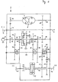
- a built-in gear 2 can be seen, which has no load-bearing functions in a vehicle can be installed.
- the driving force of an engine is from a transmission input shaft 4 in the Transfer gear 2.
- the input shaft 4 has an extension 5, the PTO can serve to drive downstream machines.
- the branches in the transmission on the gear 6 driving force via the hydrostatic actuator 8 drive-connected gear 10 in a hydrostatic and via the gear 12 in one mechanical power share.
- the arrow 9 symbolizes in the hydrostatic actuating gear 8 a pivoting position of the hydrostat.
- hydrostatic actuator 8 about the hydrostatic power share transmitting output shaft 14 and the gear 16 connected to it in a rotationally fixed manner hydrostatic actuator 8 in constant operative connection with the sun gear shaft 18 of the Planetary gear 20, here consisting of the planetary gear sets 0, I and II.
- the mechanical Power share is in the planetary gear via the step shaft II or ring gear shaft 22 20 introduced.
- the oil pump 13 is drive-connected to the shaft 22.
- the Output from the planetary gear 20 takes place via the non-rotatably connected to the ring gear shaft 24 Gears 26 and 28, via the gear 32 non-rotatably connected to the web 30 and via the gear 36 connected to the sun gear shaft 34 in a rotationally fixed manner.
- the gear wheels 26, 28, 32 and 36 are rotatable on a coupling shaft (Reverse gear input shaft 38 stored gears 40, 42, 44 and 46 of a 4-speed manual transmission in operative connection.
- the drive forces can be switched through to the clutch shaft 38 become.
- the couplings of the transmission 2 can be non-positive or positive Clutches be formed.
- a Reverse gear 48 arranged in which by actuating the clutch 50 between forward and Reverse gear can be switched back and forth.
- the steps 47/52 and 49/54 with intermediate gear 51 should have the same or similar translation. If full reversibility is not desired, You can of course choose translations that differ significantly from each other.
- the driving force is applied to the gear wheels 52 or 54 steered, which are non-rotatably mounted on the hollow shaft 56 and the drive energy via the Longitudinal differential gear 58 on the rear axle shaft 60 to the rear axle HA and the front axle shaft 62 transmits to the front axle VA of a vehicle.
- the longitudinal differential can in shown example can be optionally locked by a clutch K8. Instead of The longitudinal differential can be a smooth shaft, the front and rear axles rotatably with each other connects, used.
- the hydrostatic adjustment gear 8 is no longer pivoted into another extreme position are, it is sufficient in the regulated standstill of the coupling shaft 38, the coupling sleeve Coupling 50 from one position KV or KR to the other position KV or KR move what is possible in fractions of a second.
- a switchover can do so quickly that they are for the operator of the vehicle in which the transmission 2 located, can no longer be perceived as a time delay.
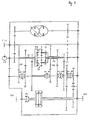
- Figure 2 shows a modification of the proposed transmission.
- the construction shown in Figure 2 is comparable to that of Figure 1; the essential difference is that on the shaft 24 and on the shaft 34 each additional gear 64, 66 attached and an additional double clutch is provided, whereby instead of the 4-speed manual transmission shown in Figure 1, a 6-speed manual transmission results.
- the output speed of the sun gear shaft 18 is shown on the abscissa and the achievable speed in km / h is shown on the ordinate.
- V forwards
- R backwards
- the driving force is coupled from the clutch 50 to the forward or reverse gear group.
- the vehicle equipped with the transmission according to the invention picks up speed by pivoting the hydrostratic actuating gear 8 in the + direction in the first driving range, which extends up to a speed of 3.5 km / h.
- the adjustment unit is swiveled fully back and the next higher gear must be engaged if the acceleration is to be continued. In the end, the shown top speed of 45 km / h can be reached. If a reduction in speed is desired, the gearbox is regulated in the opposite direction along the characteristic curve shown. Other speed values result when a different transmission ratio is selected and / or the individual sentences of the planetary gear 20 are assigned to one another in different ways. A person skilled in the art can easily adapt the proposed concept to the general conditions of a particular use.
- the characteristic curve shown in FIG. 3 for a 6-speed transmission can of course be varied and designed for other numbers of gears according to the requirements.
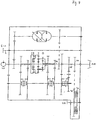
- FIG. 4 shows a transmission according to the invention as a so-called block construction transmission.
- Block gearboxes can have the gearbox arranged between the motor and axle supporting properties take.
- This transmission is also still in its structure and function comparable to the transmission shown in Figure 1. Differences arise here by the output shaft 68 is attached to the rear axle on the sun gear shaft 18, so that it have the same turning center and thus enables a flatter construction of the gear.
- the usual center distances between the input shaft are 4 and output shaft 68 possible, as they are from different tractor manufacturers be specified.
- the drive to the front axle is via any gear stage derived from the output shaft 68 and is or via a multi-plate clutch 70 switched off.
- the front axle speeds VA can be adjusted via level 71/72.
Claims (19)
- Transmission hydromécanique (2) à variation continue à division de puissance,caractérisée en ce quecomprenant une transmission réversible (48) avec un arbre d'entrée (38) et un arbre de sortie associés, un variateur de couple (8) hydrostatique, au moins un engrenage planétaire (20) et des rapports de vitesses sélectionnables, placés derrière,dans laquelle un arbre d'entrée (4) qui transmet la part de puissance mécanique et un arbre de sortie (14) du variateur de couple hydrostatique est en prise permanente avec l'engrenage planétaire,dans laquelle la part de puissance transmise par le variateur de couple hydrostatique et la vitesse de rotation sont variablesdans laquelle la transmission réversible est placée derrière l'engrenage planétaire, qui additionne les parts de puissance mécanique et hydrostatique,sur l'arbre d'entrée (38) de la transmission réversible, qui reçoit un premier étage de roues dentées et un deuxième étage de roues dentées avec un pignon intermédiaire pour l'inversion du sens de rotation, est monté un pignon des rapports de vitesses sélectionnables,les pignons menants des étages de pignons sont disposés sur l'arbre d'entrée de la transmission réversible et les pignons menés des étages de pignons sont solidaires de l'arbre de sortie de la transmission réversible,les pignons menants pouvant être couplés de manière sélective à l'arbre d'entrée de la transmission réversible par l'intermédiaire d'un embrayage (50).
- Transmission selon la revendication 1, caractérisée en ce que le rapport de démarrage est à division de puissance hydrostatique-mécanique.
- Transmission selon une ou plusieurs des revendications 1 à 2, caractérisée en ce que le variateur de couple (8) hydrostatique pour le démarrage vers l'avant ou vers l'arrière est dans la même position extrême.
- Transmission selon une ou plusieurs des revendications 1 à 3, caractérisée en ce que l'arbre d'entrée (4) est prolongé et peut être utilisé comme arbre de prise de puissance
- Transmission selon une ou plusieurs des revendications 1 à 4, caractérisée en ce que grâce à un pignon (6) monté sur l'arbre d'entrée (4), le variateur de couple (8) hydrostatique ainsi qu'un arbre (22) de l'engrenage planétaire (20) sont entraínés simultanément.
- Transmission selon une ou plusieurs des revendications 1 à 5, caractérisée en ce que l'alimentation en huile du variateur de couple (8) hydrostatique et la lubrification de la transmission sont assurées par une pompe à huile entraínée par un arbre de la transmission.
- Transmission selon une ou plusieurs des revendications 1 à 6, caractérisée en ce que le rapport de transmission de base d'un jeu de roues planétaires (0) de l'engrenage planétaire (20) est choisi tel que, pour une vitesse de rotation donnée de l'arbre (22) assurant la transmission de la part de puissance mécanique, et une vitesse de rotation de même valeur mais opposée d'un arbre (18) assurant la transmission de la part de puissance hydrostatique, la vitesse d'un arbre de démarrage (34) est égale à zéro.
- Transmission selon une ou plusieurs des revendications 1 à 7, caractérisée en ce que les rapports de vitesses sont choisis tels, que pour obtenir une égalité de vitesse de rotation aux points de changement de vitesse, le variateur de couple hydrostatique doit être rempli à environ 80%.
- Transmission selon une ou plusieurs des revendications 1 à 8, caractérisée en ce que deux rapports de vitesses (36, 46 et 28, 42) d'une part et deux rapports de vitesses (32, 44 et 26, 40) d'autre part présentent le même rapport de démultiplication.
- Transmission selon une ou plusieurs des revendications 1 à 9, caractérisée en ce que les embrayages (50, K1-K4) sont des embrayages à friction ou des embrayages positifs.
- Transmission selon une ou plusieurs des revendications 1 à 10, caractérisée en ce que l'arbre d'entrée (38) de la transmission réversible est réalisé d'une pièce ou est formé de plusieurs tronçons solidaires les uns des autres en rotation.
- Transmission selon une ou plusieurs des revendications 1 à 11, caractérisée en ce que les roues dentées des étages de transmission de la transmission réversible ont des rapports de transmission identiques ou similaires.
- Transmission selon une ou plusieurs des revendications 1 à 12, caractérisée en ce qu'un essieu avant et un essieu arrière d'un véhicule peuvent être couplés l'un à l'autre par l'intermédiaire d'un différentiel longitudinal verrouillable.
- Transmission selon une ou plusieurs des revendications 7 à 13, caractérisée en ce que l'arbre de sortie (68) de la transmission réversible menant à l'essieu arrière a le même centre de rotation que l'arbre (18).
- Transmission selon une ou plusieurs des revendications 1 à 14, caractérisée en ce que dans le cas d'une transmission de type compacte la vitesse de rotation de l'essieu avant peut être adapté au moyen d'un étage de transmission (71/72).
- Transmission selon une ou plusieurs des revendications 1 à 15, caractérisée en ce que l'essieu avant peut être connecté par l'intermédiaire d'un embrayage à disques.
- Transmission selon une ou plusieurs des revendications 1 à 16, caractérisée en ce qu'il est prévu derrière le train d'engrenages planétaires (1) de la transmission planétaire (20), un étage de transmission, derrière le train d'engrenages planétaires (0) de la transmission planétaire (20), un étage de transmission, et derrière le train d'engrenages planétaires (II) de la transmission planétaire (20), deux étages de transmission.
- Transmission selon une ou plusieurs des revendications 1 à 16, caractérisée en ce qu'il est prévu derrière le train d'engrenages planétaires (1), deux étages de transmission, derrière le train d'engrenages planétaires (0), un étage de transmission, et derrière le train d'engrenages planétaires (II) deux étages de transmission.
- Transmission selon une ou plusieurs des revendications 1 à 16, caractérisée en ce qu'il est prévu derrière le train d'engrenages planétaires (1), deux étages de transmission, derrière le train d'engrenages planétaires (0), un étage de transmission, et derrière le train d'engrenages planétaires (II) trois étages de transmission
Applications Claiming Priority (2)
| Application Number | Priority Date | Filing Date | Title |
|---|---|---|---|
| DE19628330 | 1996-07-13 | ||
| DE19628330A DE19628330A1 (de) | 1996-07-13 | 1996-07-13 | Hydrostatisch-mechanisch leistungsverzweigtes Lastschaltgetriebe |
Publications (3)
| Publication Number | Publication Date |
|---|---|
| EP0818643A2 EP0818643A2 (fr) | 1998-01-14 |
| EP0818643A3 EP0818643A3 (fr) | 1999-02-03 |
| EP0818643B1 true EP0818643B1 (fr) | 2002-10-09 |
Family
ID=7799770
Family Applications (1)
| Application Number | Title | Priority Date | Filing Date |
|---|---|---|---|
| EP97110718A Expired - Lifetime EP0818643B1 (fr) | 1996-07-13 | 1997-07-01 | Transmission hydromécanique à division de puissance |
Country Status (2)
| Country | Link |
|---|---|
| EP (1) | EP0818643B1 (fr) |
| DE (2) | DE19628330A1 (fr) |
Families Citing this family (15)
| Publication number | Priority date | Publication date | Assignee | Title |
|---|---|---|---|---|
| DE19955312B4 (de) * | 1999-11-17 | 2005-10-27 | Jungheinrich Ag | Antriebssystem für Flurförderzeuge |
| DE10304917B4 (de) * | 2003-02-07 | 2017-05-11 | Zf Friedrichshafen Ag | Stufenloses Getriebe |
| DE10322232B4 (de) * | 2003-05-17 | 2012-02-02 | Zf Friedrichshafen Ag | Leistungsverzweigungsgetriebe |
| DE102004042113A1 (de) * | 2004-08-30 | 2006-04-06 | Claas Selbstfahrende Erntemaschinen Gmbh | Antrieb einer Zuführvorrichtung für landwirtschaftliche Arbeitsmaschinen |
| US7530913B2 (en) | 2005-06-03 | 2009-05-12 | Caterpillar Inc. | Multi-range hydromechanical transmission |
| KR101029209B1 (ko) * | 2006-07-06 | 2011-04-12 | 가부시끼 가이샤 구보다 | 변속 전동 장치 |
| DE102008001612B4 (de) * | 2008-05-07 | 2020-10-29 | Zf Friedrichshafen Ag | Stufenloses Leistungsverzweigungsgetriebe |
| DE102010029866A1 (de) * | 2010-06-09 | 2011-12-15 | Zf Friedrichshafen Ag | Stufenloses Leistungsverzweigungsgetriebe mit einem Variator |
| EP2795159B1 (fr) | 2011-12-23 | 2019-06-26 | Volvo Construction Equipment AB | Transmission variable continue et machine de travail comprenant une transmission à réglage continu |
| DE102017219995A1 (de) * | 2017-11-10 | 2019-05-16 | Zf Friedrichshafen Ag | Stufenloses Leistungsverzweigungsgetriebe |
| US11261951B2 (en) | 2017-11-24 | 2022-03-01 | Kubota Corporation | Shift power transmission apparatus of a tractor and tractor |
| JP7034051B2 (ja) * | 2017-11-24 | 2022-03-11 | 株式会社クボタ | トラクタの変速伝動装置及びトラクタ |
| AT521773B1 (de) * | 2018-11-13 | 2020-05-15 | Avl Commercial Driveline & Tractor Eng Gmbh | Antriebsstrang für ein Kraftfahrzeug |
| DE102019208948A1 (de) * | 2019-06-19 | 2020-12-24 | Deere & Company | Lastschaltgetriebe |
| DE102019219353A1 (de) * | 2019-12-11 | 2021-06-17 | Zf Friedrichshafen Ag | Leistungsverzweigungsgetriebe, Antriebsstrang und Verfahren zum Betrieb eines Leistungsverzweigungsgetriebes |
Family Cites Families (6)
| Publication number | Priority date | Publication date | Assignee | Title |
|---|---|---|---|---|
| DE3925732C1 (fr) * | 1989-08-03 | 1991-01-17 | Holmer, Alfons, 8306 Schierling, De | |
| EP0521195B1 (fr) * | 1991-07-04 | 1995-06-07 | CLAAS Kommanditgesellschaft auf Aktien | Transmission hydromécanique à division de puissance |
| DE4127266A1 (de) * | 1991-08-17 | 1993-02-18 | Deere & Co | Fahrzeuggetriebe mit zentraldifferential |
| GB9213703D0 (en) * | 1992-06-27 | 1992-08-12 | Massey Ferguson Sa | Transmissions |
| DE4323358C1 (de) * | 1993-05-28 | 1994-05-26 | Jarchow Friedrich | Lastschaltgetriebe mit stufenlosen hydrostatischen Gangübersetzungen |
| DE4443267A1 (de) * | 1994-12-05 | 1996-06-13 | Claas Ohg | Lastschaltgetriebe mit 5-welligem Umlaufgetriebe |
-
1996
- 1996-07-13 DE DE19628330A patent/DE19628330A1/de not_active Withdrawn
-
1997
- 1997-07-01 EP EP97110718A patent/EP0818643B1/fr not_active Expired - Lifetime
- 1997-07-01 DE DE59708411T patent/DE59708411D1/de not_active Expired - Fee Related
Also Published As
| Publication number | Publication date |
|---|---|
| DE19628330A1 (de) | 1998-01-15 |
| EP0818643A2 (fr) | 1998-01-14 |
| DE59708411D1 (de) | 2002-11-14 |
| EP0818643A3 (fr) | 1999-02-03 |
Similar Documents
| Publication | Publication Date | Title |
|---|---|---|
| AT414345B (de) | Leistungsverzweigungsgetriebe für kraftfahrzeuge | |
| EP0716248B1 (fr) | Transmission de changement de vitesse sous charge avec transmission orbitale à cinq arbres | |
| EP0081696B1 (fr) | Transmission hydromécanique avec division de puissance à l'entrée | |
| DE3726080C2 (fr) | ||
| EP0818643B1 (fr) | Transmission hydromécanique à division de puissance | |
| DE1804188A1 (de) | Hydromechanisches Getriebe fuer Kraftfahrzeuge | |
| DE10319252A1 (de) | Stufenlos leistungsverzweigtes Getriebe | |
| EP0521195A1 (fr) | Transmission hydromécanique à division de puissance | |
| DE4343402A1 (de) | Stufenloses hydrostatisches Leistungsverzweigungsgetriebe | |
| EP2195553A1 (fr) | Transmission à répartition de puissance | |
| WO1989009899A1 (fr) | Boite de vitesses hydrostatique-mecanique a derivation de puissance | |
| WO2009127324A2 (fr) | Agencement d'essieu moteur d'un véhicule avec boîte de transfert | |
| DE19747459C2 (de) | Hydrostatisch-mechanischer Fahrantrieb | |
| EP0528319B1 (fr) | Transmission pour véhicules avec différentiel central | |
| DE2757399A1 (de) | Schaltgetriebe | |
| DE2557243A1 (de) | Kraftuebertragungsvorrichtung mit veraenderbarer uebersetzung | |
| DE60317975T2 (de) | Stufenloses Getriebe für Kraftfahrzeuge, insbesondere für landwirtschaftliche Traktoren | |
| DE102004001929A1 (de) | Hydrostatisch-mechanisches Leistungsverzweigungsgetriebe | |
| DE102020203391A1 (de) | Leistungsverzweigtes stufenloses Getriebe | |
| DE10201687B4 (de) | Toroidgetriebe mit Anlaufkupplung | |
| DE3733152C2 (fr) | ||
| DE3836017C2 (fr) | ||
| DE102020201692B3 (de) | Leistungsverzweigtes stufenloses Getriebe | |
| DE102020201690B3 (de) | Leistungsverzweigtes stufenloses Getriebe | |
| DE4125988A1 (de) | Hydrostisch-leistungsverzweigtes mehrganggetriebe |
Legal Events
| Date | Code | Title | Description |
|---|---|---|---|
| PUAI | Public reference made under article 153(3) epc to a published international application that has entered the european phase |
Free format text: ORIGINAL CODE: 0009012 |
|
| AK | Designated contracting states |
Kind code of ref document: A2 Designated state(s): DE FR GB IT SE |
|
| PUAL | Search report despatched |
Free format text: ORIGINAL CODE: 0009013 |
|
| AK | Designated contracting states |
Kind code of ref document: A3 Designated state(s): AT BE CH DE DK ES FI FR GB GR IE IT LI LU MC NL PT SE |
|
| 17P | Request for examination filed |
Effective date: 19990803 |
|
| AKX | Designation fees paid |
Free format text: DE FR GB IT SE |
|
| 17Q | First examination report despatched |
Effective date: 20010226 |
|
| GRAG | Despatch of communication of intention to grant |
Free format text: ORIGINAL CODE: EPIDOS AGRA |
|
| GRAG | Despatch of communication of intention to grant |
Free format text: ORIGINAL CODE: EPIDOS AGRA |
|
| GRAH | Despatch of communication of intention to grant a patent |
Free format text: ORIGINAL CODE: EPIDOS IGRA |
|
| GRAG | Despatch of communication of intention to grant |
Free format text: ORIGINAL CODE: EPIDOS AGRA |
|
| GRAH | Despatch of communication of intention to grant a patent |
Free format text: ORIGINAL CODE: EPIDOS IGRA |
|
| GRAH | Despatch of communication of intention to grant a patent |
Free format text: ORIGINAL CODE: EPIDOS IGRA |
|
| GRAA | (expected) grant |
Free format text: ORIGINAL CODE: 0009210 |
|
| AK | Designated contracting states |
Kind code of ref document: B1 Designated state(s): DE FR GB IT SE |
|
| REG | Reference to a national code |
Ref country code: GB Ref legal event code: FG4D Free format text: NOT ENGLISH |
|
| REF | Corresponds to: |
Ref document number: 59708411 Country of ref document: DE Date of ref document: 20021114 |
|
| GBT | Gb: translation of ep patent filed (gb section 77(6)(a)/1977) |
Effective date: 20021119 |
|
| ET | Fr: translation filed | ||
| PLBE | No opposition filed within time limit |
Free format text: ORIGINAL CODE: 0009261 |
|
| STAA | Information on the status of an ep patent application or granted ep patent |
Free format text: STATUS: NO OPPOSITION FILED WITHIN TIME LIMIT |
|
| 26N | No opposition filed |
Effective date: 20030710 |
|
| PGFP | Annual fee paid to national office [announced via postgrant information from national office to epo] |
Ref country code: IT Payment date: 20070726 Year of fee payment: 11 |
|
| PG25 | Lapsed in a contracting state [announced via postgrant information from national office to epo] |
Ref country code: IT Free format text: LAPSE BECAUSE OF NON-PAYMENT OF DUE FEES Effective date: 20080701 |
|
| PGFP | Annual fee paid to national office [announced via postgrant information from national office to epo] |
Ref country code: FR Payment date: 20090720 Year of fee payment: 13 |
|
| PGFP | Annual fee paid to national office [announced via postgrant information from national office to epo] |
Ref country code: SE Payment date: 20090727 Year of fee payment: 13 Ref country code: GB Payment date: 20090724 Year of fee payment: 13 Ref country code: DE Payment date: 20090623 Year of fee payment: 13 |
|
| GBPC | Gb: european patent ceased through non-payment of renewal fee |
Effective date: 20100701 |
|
| REG | Reference to a national code |
Ref country code: FR Ref legal event code: ST Effective date: 20110331 |
|
| PG25 | Lapsed in a contracting state [announced via postgrant information from national office to epo] |
Ref country code: DE Free format text: LAPSE BECAUSE OF NON-PAYMENT OF DUE FEES Effective date: 20110201 |
|
| REG | Reference to a national code |
Ref country code: DE Ref legal event code: R119 Ref document number: 59708411 Country of ref document: DE Effective date: 20110201 |
|
| PG25 | Lapsed in a contracting state [announced via postgrant information from national office to epo] |
Ref country code: FR Free format text: LAPSE BECAUSE OF NON-PAYMENT OF DUE FEES Effective date: 20100802 |
|
| PG25 | Lapsed in a contracting state [announced via postgrant information from national office to epo] |
Ref country code: GB Free format text: LAPSE BECAUSE OF NON-PAYMENT OF DUE FEES Effective date: 20100701 |
|
| PG25 | Lapsed in a contracting state [announced via postgrant information from national office to epo] |
Ref country code: SE Free format text: LAPSE BECAUSE OF NON-PAYMENT OF DUE FEES Effective date: 20100702 |