EP0815890A2 - Procédé de fabrication d'un dispositif de protection d'aiguille - Google Patents
Procédé de fabrication d'un dispositif de protection d'aiguille Download PDFInfo
- Publication number
- EP0815890A2 EP0815890A2 EP97304549A EP97304549A EP0815890A2 EP 0815890 A2 EP0815890 A2 EP 0815890A2 EP 97304549 A EP97304549 A EP 97304549A EP 97304549 A EP97304549 A EP 97304549A EP 0815890 A2 EP0815890 A2 EP 0815890A2
- Authority
- EP
- European Patent Office
- Prior art keywords
- needle
- needle shield
- collar
- hub
- cannula
- Prior art date
- Legal status (The legal status is an assumption and is not a legal conclusion. Google has not performed a legal analysis and makes no representation as to the accuracy of the status listed.)
- Granted
Links
Images


Classifications
-
- A—HUMAN NECESSITIES
- A61—MEDICAL OR VETERINARY SCIENCE; HYGIENE
- A61M—DEVICES FOR INTRODUCING MEDIA INTO, OR ONTO, THE BODY; DEVICES FOR TRANSDUCING BODY MEDIA OR FOR TAKING MEDIA FROM THE BODY; DEVICES FOR PRODUCING OR ENDING SLEEP OR STUPOR
- A61M5/00—Devices for bringing media into the body in a subcutaneous, intra-vascular or intramuscular way; Accessories therefor, e.g. filling or cleaning devices, arm-rests
- A61M5/178—Syringes
- A61M5/31—Details
- A61M5/32—Needles; Details of needles pertaining to their connection with syringe or hub; Accessories for bringing the needle into, or holding the needle on, the body; Devices for protection of needles
- A61M5/3202—Devices for protection of the needle before use, e.g. caps
-
- A—HUMAN NECESSITIES
- A61—MEDICAL OR VETERINARY SCIENCE; HYGIENE
- A61M—DEVICES FOR INTRODUCING MEDIA INTO, OR ONTO, THE BODY; DEVICES FOR TRANSDUCING BODY MEDIA OR FOR TAKING MEDIA FROM THE BODY; DEVICES FOR PRODUCING OR ENDING SLEEP OR STUPOR
- A61M5/00—Devices for bringing media into the body in a subcutaneous, intra-vascular or intramuscular way; Accessories therefor, e.g. filling or cleaning devices, arm-rests
- A61M5/178—Syringes
- A61M5/31—Details
- A61M5/32—Needles; Details of needles pertaining to their connection with syringe or hub; Accessories for bringing the needle into, or holding the needle on, the body; Devices for protection of needles
- A61M5/3205—Apparatus for removing or disposing of used needles or syringes, e.g. containers; Means for protection against accidental injuries from used needles
- A61M5/321—Means for protection against accidental injuries by used needles
- A61M5/3216—Caps placed transversally onto the needle, e.g. pivotally attached to the needle base
Definitions
- the subject invention relates to needle shields for hypodermic needles, to help prevent accidental contact with the needle.
- a needle shield which is hinged near the base of the needle has the advantage of allowing one-handed needle reshielding, thus providing the opportunity for reshielding, under most circumstances, immediately after use.
- a hinged needle shield which permanently locks when it is pivoted to the closed needle shielding position has certain advantages. Primarily, there is no doubt about the status of the needle shield assembly and the healthcare worker knows that the needle should be carefully disposed of and not used for further fluid transfer. This is analogous to the prior art rigid cylindrical needle shield which is telescoped over the needle cannula and frictionally engages the needle hub. It is clear with the prior art needle assembly whether the needle is shielded or not shielded.
- having a permanently lockable hinged needle shield presents a problem in situations where the needle is intended to be used twice. For example, the needle is first used to penetrate the pierceable stopper of a medication vial for the purpose of filing the syringe with medication for subsequent injection into a patient.
- the needle shield assembly with attached syringe is then transported to the patient area for injection of the medication. If the needle is re-shielded permanently after the syringe is filled it cannot be used for injection and a second needle must be installed at the time of use.
- a self-contained needle shield assembly wherein the adapter for the medical implement, the needle cannula, and the needle shield are all connected in one unit.
- the prior art includes syringes having cylindrical sleeves over their outside diameter. After injection, the sleeve is advanced to a locked needle protecting position.
- the syringes are important safety devices, however, not all syringes are used with a needle.
- the use of a self-contained needle shield assembly allows the end user to attach the needle assembly onto a variety of syringe sizes and to inventory standard syringes for all uses. Accordingly, a more costly safety syringe would not have to be used for applications where the safety features are not necessary.
- An enclosed needle cover that protects the cleanliness of the needle even after the needle shield assembly is removed from its sterile package.
- An enclosed needle cover protects all sides of the needle while a hinged needle shield has one open side and allows exposure of the needle to airborne particles.
- a self-contained needle shield assembly wherein the needle shield can be positioned in the needle shielding position using a one-handed procedure and the needle shield automatically locks in the needle shielding position and is unable to be reused.
- a self-contained needle shield assembly which allows the needle to be used twice, once for withdrawing medication into a syringe and then for injecting the medication into a patient wherein the needle may be shielded between the first and second use.
- a needle shield assembly which protects the cleanliness of the needle after the needle shield assembly is removed from its sterile package.
- a needle shield assembly that provides the shortest possible fluid path between the syringe barrel and the needle tip to avoid loss of medication in the fluid path which cannot be expelled.
- a needle shield assembly having a single-use cannula lock of the present invention includes a needle cannula having a proximal end, a distal end and a lumen therethrough.
- a hub includes a proximal end for connection to a fluid transfer device and a distal end connected to the proximal end of the needle cannula.
- a collar is rotationally connected to the hub so that the collar can be rotated around the hub.
- An elongate needle cover removably engages the hub and covers the needle cannula.
- An elongate needle shield having a proximal end and a distal end is hingedly connected, through its proximal end, to the collar.
- the needle shield includes two sidewalls defining a longitudinal opening and a back wall between said side walls defining a recess having an interior surface.
- the needle shield is capable of pivoting from an open position wherein the needle cannula is exposed, to a closed needle protecting position wherein the needle cannula is within the longitudinal opening of the needle shield.
- the needle shield assembly further includes structure for preventing the needle shield from pivoting into the closed position unless the needle cover is removed, and structure for locking the needle shield in the closed needle protecting position when the needle shield is pivoted into the closed position. The structure for locking traps the needle cannula in the longitudinal opening of the needle shield.
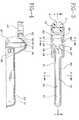
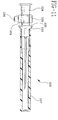
- Fig. 1 is a side elevation view of the needle shield assembly of the present invention attached to a syringe before being used.
- Fig. 2 is an exploded view illustrating the needle shield assembly of the present invention attached to a syringe with the needle cover and portions of the hub illustrated in cross-section.
- Fig. 3 is a top plan view of a needle shield and collar assembly for use in the present invention.
- Fig. 4 is a cross-sectional view of the needle shield and collar assembly of Fig. 3 taken along lines 4-4.
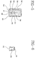
- Fig. 5 is a cross-sectional view of the needle shield and collar assembly of Fig. 3 taken along lines 5-5.
- Fig. 6 is a cross-sectional view of the needle shield and collar assembly of Fig. 3 taken along lines 6-6.
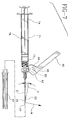
- Fig. 7 is a side elevation view of the needle shield assembly of the present invention attached to a syringe at the time of first use.
- Fig 8 is a side elevation view of the needle shield assembly of the present invention after use with the needle shield in the closed position.
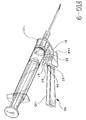
- Fig. 9 is a perspective view of an alternative needle shield assembly of the present invention attached to a syringe.
- Fig. 10 is a cross-sectional view of an alternative needle shield.
- Fig. 11 is a side elevation view of an alternative needle shield assembly of the present invention illustrated without the collar and needle shield.
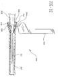
- Fig. 12 is another alternative embodiment of the present needle shield assembly.
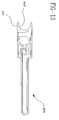
- Fig. 13 illustrates an alternative needle shield and collar assembly.
- a needle shield assembly having a single-use cannula lock such as needle shield assembly 20, includes a needle cannula 21 having a proximal end 22, a distal end 23 and a lumen therethrough defining a longitudinal axis 25.
- the distal end of the needle cannula includes sharpened tip 26.
- blunt cannula which are cannula without sharp tips.
- Blunt cannula are known in the art and are usually used to inject liquid into an I.V. set or other fluid path having an access port with a pre-slit septum. The blunt cannula is forced through the slit in the septum and into fluid communication with the fluid flow path. Upon removal of the blunt cannula, the slit portion of the septum automatically seals itself.
- a hub 28 includes a proximal end 29 and a distal end 31 connected to proximal end 22 of the needle cannula.
- the hub includes a base member 30 which for the purposes of describing the instant invention is part of the hub.
- There are many ways of connecting the base member to the hub such as through interference fit, adhesives, ultrasonic welding and the like. It is within the purview of the present invention to include a hub and its base member which are of a unitary one-piece structure.
- the one-piece structure may be accomplished by many methods including injection molding the hub and base member as a one-piece unit thereby eliminating the need to assemble the base member to the hub during the manufacturing process.
- the collar is rotatably connected to the hub in a snap-fit arrangement which allows the collar, through application of manual force, to be rotated around the hub.
- the rotational connection of the collar and hub is accomplished by interaction between structure on the hub including proximal raised portion 32, distal raised portion 33 and collar receiving recess 34 and the collar.
- the distance across proximal raised portion 32 and distal raised portion 33 is greater than the inside diameter of collar 41 and greater than the diameter or distance across recess 34.
- the collar is passed over the distal end of the hub and forced over distal raised portion 33 so that it snaps into the space between raised portion 32 and raised portion 33 and is trapped in that position.
- Interior surface 43 of collar 41 can be formed in a variety of shapes such as a constant inside diameter. In this preferred embodiment, interior surface 43 is defined by four segments along minor diameter C and four segments along major diameter D, as best illustrated in Fig. 3. Minor diameter C is slightly smaller than the diameter of recess 34 on hub 28.
- This stepped configuration makes the collar less sensitive to manufacturing tolerances so that the frictional fit between the collar and the hub can be more tightly controlled. The stepped configuration also gives the collar some flexibility to allow it to be easily snapped into place during the assembly process. The advantages of rotationally connecting the collar to the hub will be explained in more detail hereinafter.
- a needle cover is an important advantage of the present invention.
- the needle assembly is manufactured and sterilized in a protective package with the needle cover in place.
- the needle cover provides a contamination barrier for the needle after the needle shield assembly is removed from the sterile package. Accordingly, the user is assured of a clean needle at the time of first use.
- the needle cover is removed, as illustrated in Fig. 7, by overcoming engagement forces between the needle hub and the open proximal end of the needle cover.
- Needle shield 45 having a distal end 46 and a proximal end 47 is hingedly connected to collar 41.
- needle shield 45 is hingedly connected to collar 41 through living hinge 44. It is within the purview of the present invention to include any structure for hingedly connecting the shield to the collar so that the needle shield may be pivoted with respect to the collar. These structures include known mechanical hinges and various linkages, or combinations of hinges and linkages.
- Needle shield 45 includes two side walls 50 and 51 defining a longitudinal opening 52 and a back wall 53 between the side walls defining a recess 55 having an interior surface 56.
- the needle shield assembly of the present invention is suitable for use with fluid delivery devices such as syringes.
- needle shield assembly 20 is illustrated connected to hypodermic syringe 70 comprising a syringe barrel 71 having a distal end 73, a proximal end 74 and a circular side wall 75 defining a chamber 76 for retaining fluid and a longitudinal axis 80.
- Volume measuring indicia 72 are on the barrel for measuring the dose of medication to be delivered.
- the distal end of the syringe barrel is connected to the hub so that the lumen of the needle cannula is in fluid communication with chamber 76 of the syringe barrel.
- distal end 73 of the syringe barrel includes a frusto-conically shaped tip 77 having a passageway therethrough which provides a fluid path between the cannula and the chamber.
- the frusto-conically shaped tip of the syringe barrel frictionally engages a frusto-conically shaped cavity in the needle hub.
- the distal end of the syringe barrel also includes a locking luer-type collar 79 concentrically surrounding the tip.
- the luer collar has an internal thread which engages the needle hub to hold it securely to the barrel. It is within the scope of the present invention to include various hub configurations to attach to a wide variety of medical or other fluid handling devices.
- the hub configuration described hereinabove having a frusto-conically shaped interior cavity, reflects one of these many possibilities.
- Many syringes, fluid handling devices, such as stopcocks and adapters, and other fluid handling devices contain luer slip and locking luer-type fittings to which the hub of a frusto-conically shaped interior cavity will properly engage. It is also within the purview of the present invention to provide a needle shield assembly wherein the hub is integrally molded with the syringe barrel.
- the hub is capable of directly connecting to a fluid handling device such as a syringe.
- a fluid handling device such as a syringe.
- Some prior art devices contain a separate housing which mounts between the needle hub and the syringe, wherein the needle shield is hingedly connected to the separate housing.
- a separate housing lengthens the fluid flow path between the chamber in the syringe and the distal end of the needle cannula thereby wasting medication, because it cannot be expelled, the fluid flow path through the housing must be filled with medication before medication can leave the proximal end of the needle.
- the medication may cost one hundred times more than the syringe and small amounts of medication lost over a substantial number of syringes can result in a substantial unnecessary loss of valuable medication.
- the additional element increases the length between the syringe and the needle tip possibly making it slightly more difficult to accurately position the needle, for example in a patient's vein.
- the use of a needle cover and a hinged needle shield in the needle shield assembly of the present invention provides other advantages in the manufacturing and assembling of the needle shield assembly.
- the needle cannula, hub and needle cover can be manufactured as a separate assembly. So long as the needle cover is attached to the hub the needle cannula and in particular the sharpened tip of the needle cannula is protected from damage and contamination.
- the final assembly step involves slipping collar 41 over needle cover 37 until the collar snaps into place on the collar receiving recess 34 of the hub.
- needle cover 37 includes annular flange 40 which has a tapered outside surface to allow the collar to pass smoothly over annular flange 40 and distal raised portion 33 of the hub and into recess 34 during assembly. Further, this final assembly step is accomplished while the fragile needle cannula is protected by needle cover 37, thus avoiding contamination and damage to the needle cannula.
- Needle shield 45 is capable of pivoting from an open position wherein needle cannula 21 is exposed, as best illustrated in Fig. 7, to a closed needle protecting position wherein at least part of needle cannula is within the longitudinal opening of the needle shield, as best illustrated in Fig. 8.
- an important feature of the present invention includes means for preventing the needle shield from being pivoted into the closed position before the needle cover is removed.
- means for preventing is accomplished forming at least a portion of the side walls so that the longitudinal opening is smaller than the needle cover, so that the needle cover must be removed before the needle shield can be pivoted into the closed needle protecting position.
- Another important feature of the present invention includes means for automatically locking the needle shield in the closed needle protecting position when the needle shield is pivoted into the closed position.
- Automatically is intended to mean that movement of the needle shield sufficiently into the needle protecting position will cause locking to occur automatically without further action on behalf of the user.
- Periodently is intended to mean that there is no unlocking structure, and the needle will remain shielded until proper disposal.
- the lock should generally withstand the normal forces encountered during proper disposal of the needle shield assembly. Excessive forces applied to the needle shield will bend the needle cannula but not allow the needle cannula to be re-exposed.
- means for locking the needle shield in the closed needle protecting position includes needle cannula locking means for trapping the needle cannula in the longitudinal opening of the needle shield.
- needle cannula locking means includes an arm 58 projecting from interior surface 56 of the needle shield.
- Arm 58 includes a transverse portion 61 at its free end 59.
- Transverse portion 61 includes a ledge 62 which is positioned so that when the needle shield is pivoted to the closed position, needle cannula 21 snaps past transverse portion 61 and is trapped in the needle shield by ledge 62.
- the action of the needle cannula snapping past the transverse portion can be accomplished by deflection of the arm and/or the transverse portion, by deflection of the needle cannula or by a combination of all elements so that after the needle cannula passes the transverse portion, the parts return generally to their undeflected position or at least to a position where the needle cannula cannot reverse its path and remains trapped in the recess of the needle shield.
- the retention forces are preferably such that an attempt to return the needle shield to the open needle exposing position will cause the needle to be bent in that direction but usually not re-exposed.
- arm 58 extends from interior surface 56, and in particular outwardly from back wall 53. However, the arm could also extend from either of the side walls and still achieve a similar result.
- needle cannula locking means also includes first inclined wall 64 and second inclined wall 65 having exterior surfaces 67 and 68 respectively for urging the needle cannula toward the center of longitudinal opening 52 as the needle shield is being rotated into the closed position.
- the inclined walls are especially helpful if the longitudinal axis of the needle cannula is misaligned with respect to the longitudinal axis of the hub and syringe. The exterior surfaces will urge the needle cannula toward a central position so that it properly engages and is trapped by the arm structure.
- the inclined walls are not necessary for the present invention at least one wall is desirable and two walls, as best illustrated in Figs. 3 and 5, are preferred.
- the needle shield can be moved from the open position to the closed position using a single-handed procedure. For example, by grasping syringe 70 with the fingers and advancing the needle shield from the open to the closed position by pressing on the back wall with the thumb until the needle shield is in the closed locked position.
- finger pad 69 is provided at the proximal end of the needle shield.
- Releasably retaining the needle shield in the open position may be accomplished by dimensioning parts of the assembly so that friction is created in the hinge or by using an articulated over-center hinge or by creating some interference between the needle shield and the collar which must be forcefully overcome to move the needle shield out of the open position.
- projection 82 on the collar will engage edge 85 of aperture 83 when the needle shield is pivoted to the open position. Additional force is required to pivot the needle shield out of the open position.
- longitudinal opening 52 be oriented from between about 90° to 180° from longitudinal axis 25 of the needle cannula, as best illustrated in Fig. 7, where the needle shield is rotated so that longitudinal opening 52 is about 150° from longitudinal axis 25 of the needle cannula.
- sharpened tip 26 of needle cannula 21 is sharpened to a bevel shape having a bevel surface 27 oriented at angle A with respect to longitudinal axis 25. Bevel surface 27 faces direction B.
- the rotational connection of the collar to the hub is an important feature of the present invention because it allows rotation of the needle shield so that the bevel surface faces the same side of the collar as the needle shield when the needle shield is in the open position. Rotation of the needle shield to this position optimally orients the bevel surface and makes it easier to insert the needle into a patient's vein or subcutaneously.
- bevel surface 27 facing the same side of the needle assembly as the needle shield when the needle shield is in the open position, so that the needle shield does not interfere with positioning the syringe at a low angle close to the patient's body, for example, the patient's arm, when attempting to gain access into a vein.
- the ability to rotate the needle shield with respect to the hub allows the needle shield to be positioned to avoid blocking the user's view of volume measuring indicia on the syringe barrel.
- Fig. 1 illustrates needle shield assembly 20 connected to hypodermic syringe 70 in a configuration in which it is likely to be delivered, in sterile form, from a manufacturer.
- the needle shield assembly is easier to handle for the purposes of installing it onto a fluid delivery device, such as screwing the hub onto a standard locking luer-type fitting.
- means for releasably retaining the needle shield in an intermediate position between the open position and the closed position includes protrusions 86 and 87 projecting inwardly from side walls 50 and 51 respectively engage the outer surface of needle cover 37 to bias the needle shield toward the needle cover. An additional force is required to pivotably move the needle shield from the intermediate position to the open position.
- Fig. 9 illustrates an alternative needle shield assembly of the present invention.
- the alternative needle shield assembly functions similarly to the needle shield assembly of Figs. 1-8.
- Alternative needle shield assembly 90 includes collar 141 and a needle shield 145 hingedly connected to the collar through hinge 144.
- Means for releasably retaining the needle shield in the open position includes a projection 91 on the collar and finger pads 92 and 93, on the needle shield, defining slot 94 therebetween.
- the width of slot 94 between finger pads 92 and 93 is preferably equal to or slightly less than the width of projection 91 on the collar so that when the needle shield is pivoted to the open position projection 91 enters slot 94 and is frictionally engaged therein by the sides of finger pads 92 and 93.
- Projections or recesses can be provided alternatively on projection 91 and in slot 94 to provide for a mechanical engagement of the needle shield to the collar when the needle shield is in the open position.
- the needle shield is releasably retained in this position and additional force will be needed to overcome the frictional or mechanical engagement of the projection to the needle shield to advance the needle shield to the closed position.
- Discontinuous surfaces 95 and 97 are provided to help to provide a more positive connection between the user's finger and the needle shield when advancing the needle shield to the closed position.
- Fig. 10 illustrates an alternative needle shield for use with the needle shield assembly of the present invention.
- the alternative needle shield of the embodiment of Fig. 10 functions similarly to the needle shield assembly of Figs. 1-8.
- Alternative needle shield 100 includes side walls 150 and 151 defining a longitudinal opening 152 and a back wall between the side walls defining a recess 155 having an interior surface 156.
- Needle cannula locking means for trapping the needle cannula in the longitudinal opening of the needle shield includes an arm 158 having a transverse portion 161 at its free end including a ledge 162 positioned so that when the needle shield is pivoted to the closed position, the needle cannula 121 snaps past transverse portion 161 and is trapped in the needle shield by a ledge 162.
- Fig. 11 illustrates an alternative needle shield assembly 200 of the present invention illustrated without the collar and needle shield.
- a base member 230 is integrally molded and is part of a hub 228.
- Hub 228 further includes an enlarged portion 235 to facilitate removal and installation of the needle assembly. Because the collar is rotatably connected to the hub it may be difficult to install and remove the hub from a hypodermic syringe because rotation of the assembly will cause the shield and its connected collar to rotate around hub 228.
- the enlarged surface 235 provides a surface to grab to facilitate the removal and installation of the needle shield assembly.
- enlarged portion 235 has an octagonal shape to further increase its utility as a gripping surface.
- hub 228 includes radially outwardly projecting tab 236 which further acts as an enhanced point of contact for connecting and disconnecting the needle shield assembly from a hypodermic syringe or similar device.
- Ways to facilitate the installation of the needle shield assembly of the present invention include providing structure on the hub which engages the rotatable shield when it is in the closed or intermediate position.
- ribs can be provided on needle cover 37 to facilitate rotation of the cover which in turn rotates the hub.
- side walls 50 and 51 of the needle shield can be designed to be flexible enough so that hand applied squeezing forces applied to the needle shield while it is in its intermediate position will cause the shield side walls to collapse and grab needle cover 37 so that torque may be transmitted through the needle shield, through the needle cover to the hub.
- the needle shield sidewalls can be designed to grab the hub when the needle shield is in the closed position. Accordingly, the present invention provides means for applying torque to the hub to facilitate installation and removal of a needle shield assembly from a hypodermic syringe or similar device.
- Means for applying torque include alternative accessible hub structures including those with enlarged portions, such as enlarged portion 235 and/or radially projecting tabs, such as radially projecting tab 236.
- Means for applying torque can also include structure for engaging the needle cover and the needle shield, when the needle cover is in the intermediate position and providing flexible side walls on the needle shield so that digital force will deflect the side walls causing the needle shield to grab the needle cover for transmitting torque through the cover to the hub.
- Means for applying torque can also include structure for engaging the needle shield and the hub, when the needle shield is in the closed position, by providing flexible sidewalls on the needle shield so that digital force will deflect the sidewalls causing the needle shield to grab the hub for transmitting torque through the hub.
- the structure for engaging the needle shield and the hub may be sufficiently strong that, in certain configurations, a flexible sidewall will not be necessary to apply torque from the needle shield to the needle hub.
- Structure on the needle shield for engaging the hub may include a series of inwardly projecting ledges, preferably having serrated or otherwise roughened distal ends, for contacting the hub and applying sufficient frictional force so that rotational force applied to the shield is transferred efficiently to the hub.
- Hub 228 includes proximal raised portion 232 and distal raised portion 233.
- distal raised portion 233 has a chamfered surface so that the collar (not shown) may be easily installed over needle cover 237 and into recess 234 by sliding the collar over the needle shield, forcibly past the chamfered distal raised portion 233 into recess 234.
- Fig. 12 illustrates another alternative needle shield assembly of the present invention.
- This alternative needle shield assembly functions similarly to the needle shield assembly of Figs. 1-8.
- Alternative needle shield assembly 300 like the needle shield assembly of Figs. 1-8, includes a needle cannula 321, a hub 328 which includes a base member 330, a needle cover 337 and collar 341 rotationally connected to the hub so that the collar can be rotated around the hub.
- An elongate needle shield 345 is pivotably connected to collar 341 through hinge 344.
- the base member can be a separate element attached to the hub using methods described hereinabove or integrally formed as part of the hub.
- the present embodiment has an annular flange 335. The rotational connection between collar 341 and hub 328 is affected by engagement of annular flange 335 with annular recess 336 inside collar 341.
- the needle shield and collar can be assembled to the hub after the needle cover has been installed, thereby eliminating any potential for damaging the sharp needle tip during installation of the collar and needle shield assembly.
- One way to manufacture the needle shield assembly of the present invention is to attach base member 330 to hub 328 using one of the many manufacturing processes described hereinabove.
- the needle cannula is then assembled to the hub using a variety of known methods for securing the proximal end of the needle cannula to the distal end of the hub with epoxy adhesive being preferred.
- the needle assembly comprising the hub which includes the base member, integrally formed or separately attached, and the needle cannula is then assembled to the removable needle cover.
- the needle assembly may be sterilized before further assembly into a finished product, or the collar may be joined to the needle hub by advancing the collar over the distal end of the needle cover, proximally until annular flange 335 contacts chamfered surface 342 on the collar.
- the chamfered surface is provided to allow the annular flange to spread the collar slightly so that annular flange 335 can snap into annular recess 336 in the collar.
- the needle shield may now be pivoted to its intermediate position described hereinabove, and packaged and sterilized or attached to a hypodermic syringe and packaged and sterilized.
- Sterilization may be accomplished by gas sterilization such as ETO or radiation sterilization.
- gas sterilization such as ETO or radiation sterilization
- the package can be made of one hundred percent breathable material or at least have one surface of breathable material such as a blister package with a peelable, breathable top.
- the breathable surface is necessary to carry out the gas sterilization process.
- radiation sterilization such breathable components can be used but are not necessary.
- a quantity of packaged needle shield assemblies or packaged needle shield assemblies attached to devices such as a syringe are placed in a corrugated shipper and sealed before the sterilization process.
- Fig. 13 illustrates an alternative collar and needle shield assembly 400 which functions substantially identically to the embodiment of Figs. 1-8.
- collar 441 is semi-circular shaped having an aperture 442 of less than 360° and greater than 180° in duration.
- Collar 441 can be assembled axially over the needle cover and onto the needle hub using methods described hereinabove. Also, it may be assembled by moving said collar horizontally toward said hub and snapping the aperture over the appropriate structure on the needle hub.
- the alternative needle shield and collar 400 maintains the important advantage of the present invention that collar and needle shield may be assembled to the needle hub after the needle cannula and needle cover have been installed.
- the present invention provides a self-contained needle shield assembly and a method of making wherein the needle shield can be positioned in the needle shielding position using a one-handed procedure and the needle shield automatically locks in the needle shielding position so that the needle is unable to be reused.
- the needle shield assembly of the present invention also provides structure to protect the cleanliness of the needle until the needle is first used.
- the present invention also provides a self-contained needle shield assembly which allows the needle to be used twice, once for withdrawing medication into a syringe and then for injecting medication into a patient, while providing means for preventing the permanent locking of the needle shield until the final use by preventing the needle shield from being pivoted into the closed position while the needle cover is installed.
- the present invention also provides the advantage that the needle shield can be rotated with respect to the needle hub so that the needle shield can be oriented with respect to a needle cannula which has a sharpened beveled tip having a beveled surface.
- the advantage being that the needle shield can be rotated to the same side as the needle assembly as the bevel surface faces, making it easier to pierce a patient's vein without experiencing interference from the needle shield.
- the present invention provides the advantage of not having intermediate elements separating the needle hub from the fluid handling device, such as a syringe, which can waste medication by lengthening the fluid path, and making the entire assembly longer and possibly more difficult to use.
Landscapes
- Health & Medical Sciences (AREA)
- Engineering & Computer Science (AREA)
- Heart & Thoracic Surgery (AREA)
- Vascular Medicine (AREA)
- Anesthesiology (AREA)
- Biomedical Technology (AREA)
- Hematology (AREA)
- Life Sciences & Earth Sciences (AREA)
- Animal Behavior & Ethology (AREA)
- General Health & Medical Sciences (AREA)
- Public Health (AREA)
- Veterinary Medicine (AREA)
- Environmental & Geological Engineering (AREA)
- Infusion, Injection, And Reservoir Apparatuses (AREA)
Applications Claiming Priority (2)
| Application Number | Priority Date | Filing Date | Title |
|---|---|---|---|
| US08/675,752 US5665075A (en) | 1996-07-03 | 1996-07-03 | Method of making a needle shield assembly |
| US675752 | 2000-09-29 |
Publications (3)
| Publication Number | Publication Date |
|---|---|
| EP0815890A2 true EP0815890A2 (fr) | 1998-01-07 |
| EP0815890A3 EP0815890A3 (fr) | 1998-01-14 |
| EP0815890B1 EP0815890B1 (fr) | 2003-03-19 |
Family
ID=24711836
Family Applications (1)
| Application Number | Title | Priority Date | Filing Date |
|---|---|---|---|
| EP97304549A Expired - Lifetime EP0815890B1 (fr) | 1996-07-03 | 1997-06-26 | Procédé de fabrication d'un dispositif de protection d'aiguille |
Country Status (9)
| Country | Link |
|---|---|
| US (1) | US5665075A (fr) |
| EP (1) | EP0815890B1 (fr) |
| JP (1) | JP3045487B2 (fr) |
| AU (1) | AU710007B2 (fr) |
| BR (1) | BR9703870A (fr) |
| CA (1) | CA2206391C (fr) |
| DE (1) | DE69719868T2 (fr) |
| ES (1) | ES2195087T3 (fr) |
| SG (1) | SG68615A1 (fr) |
Cited By (8)
| Publication number | Priority date | Publication date | Assignee | Title |
|---|---|---|---|---|
| US6254575B1 (en) | 1999-11-04 | 2001-07-03 | Specialized Health Products | Reaccessible medical needle safety devices and methods |
| US6280420B1 (en) | 1999-11-04 | 2001-08-28 | Specialized Health Products | Reaccessible medical needle safety devices and methods |
| US6592556B1 (en) | 2000-07-19 | 2003-07-15 | Tyco Healthcare Group Lp | Medical needle safety apparatus and methods |
| WO2005023329A2 (fr) | 2003-08-28 | 2005-03-17 | Smiths Medical Asd, Inc. | Dispositif de protection d'aiguille |
| US7001363B2 (en) | 2002-04-05 | 2006-02-21 | F. Mark Ferguson | Safety shield for medical needles |
| US7862547B2 (en) | 1999-11-04 | 2011-01-04 | Tyco Healthcare Group Lp | Safety shield for medical needles |
| US8496627B2 (en) | 2006-03-21 | 2013-07-30 | Covidien Lp | Passive latch ring safety shield for injection devices |
| CN115227914A (zh) * | 2017-09-14 | 2022-10-25 | 贝克顿迪金森法国公司 | 安全组件 |
Families Citing this family (86)
| Publication number | Priority date | Publication date | Assignee | Title |
|---|---|---|---|---|
| US6355021B1 (en) * | 1998-07-14 | 2002-03-12 | Maersk Medical A/S | Medical puncturing device |
| US6298541B1 (en) * | 1998-08-28 | 2001-10-09 | Becton, Dickinson And Company | Method for making a safety shield assembly and related combinations thereof |
| US20020072715A1 (en) * | 1998-08-28 | 2002-06-13 | Newby C. Mark | Needle assembly |
| US6440104B1 (en) * | 1998-08-28 | 2002-08-27 | Becton, Dickinson And Company | Safety shield assembly |
| US6436086B1 (en) | 1998-08-28 | 2002-08-20 | Becton Dickinson And Company | Method of using a safety shield assembly and related combinations thereof |
| US6837877B2 (en) * | 1999-08-23 | 2005-01-04 | Becton, Dickinson And Company | Safety shield assembly |
| US6699217B2 (en) | 1999-08-23 | 2004-03-02 | Becton, Dickinson And Company | Safety needle assembly |
| US6648855B2 (en) * | 1999-08-23 | 2003-11-18 | Becton, Dickinson And Company | Safety needle assembly |
| US6780169B2 (en) | 1999-08-23 | 2004-08-24 | Becton, Dickinson And Company | Safety shield assembly |
| US6840291B2 (en) * | 1999-10-15 | 2005-01-11 | Becton Dickinson And Company | Attachment for a medical device |
| US6368303B1 (en) | 1999-10-15 | 2002-04-09 | Becton, Dickinson And Company | Retracting needle syringe |
| US6517516B1 (en) | 1999-10-15 | 2003-02-11 | Becton Dickinson And Company | Method of making a retracting needle syringe |
| US8226617B2 (en) | 1999-11-04 | 2012-07-24 | Tyco Healthcare Group Lp | Safety shield apparatus and mounting structure for use with medical needle devices |
| US7198618B2 (en) * | 1999-11-04 | 2007-04-03 | Tyco Healthcare Group Lp | Safety shield for medical needles |
| FR2812817B1 (fr) * | 2000-08-09 | 2002-10-31 | Sanofi Synthelabo | Dispositif de protection d'une aiguille de seringue |
| JP2002065849A (ja) * | 2000-08-28 | 2002-03-05 | Terumo Corp | 穿刺具 |
| JP2002065850A (ja) * | 2000-08-28 | 2002-03-05 | Terumo Corp | 穿刺具 |
| US7144389B2 (en) * | 2001-03-14 | 2006-12-05 | Tyco Healthcare Group, Lp | Safety shield for medical needles |
| WO2002094340A2 (fr) | 2001-05-22 | 2002-11-28 | Becton, Dickinson And Company | Ensemble protecteur d'aiguille a protecteur d'aiguille articule |
| DK1436020T3 (da) * | 2001-07-27 | 2008-09-01 | Becton Dickinson Co | Luerkoblingssamling |
| US6830562B2 (en) | 2001-09-27 | 2004-12-14 | Unomedical A/S | Injector device for placing a subcutaneous infusion set |
| US6695819B2 (en) | 2001-10-19 | 2004-02-24 | Terumo Medical Corporation | Safety needle assembly |
| US6719737B2 (en) | 2002-05-13 | 2004-04-13 | Terumo Medical Corporation | Safety needle assembly |
| SG121744A1 (en) | 2002-11-06 | 2006-05-26 | Becton Dickinson Co | Flashback blood collection needle with needle shield |
| US20040051019A1 (en) | 2002-09-02 | 2004-03-18 | Mogensen Lasse Wesseltoft | Apparatus for and a method of adjusting the length of an infusion tube |
| DK200201823A (da) | 2002-11-26 | 2004-05-27 | Maersk Medical As | Forbindelsesstykke for en slangeforbindelse |
| US20060270947A1 (en) * | 2002-12-16 | 2006-11-30 | Crawford Jamieson W M | Safety needle assembly |
| US7250038B2 (en) * | 2003-09-09 | 2007-07-31 | Smiths Medical Asd, Inc. | Fixed needle syringe with protective needle housing |
| IL157981A (en) | 2003-09-17 | 2014-01-30 | Elcam Medical Agricultural Cooperative Ass Ltd | Auto injector |
| US8251961B2 (en) | 2003-09-22 | 2012-08-28 | Smiths Medical Asd, Inc. | Safety needle assembly and method for making the same |
| US8226576B2 (en) * | 2004-02-25 | 2012-07-24 | Becton, Dickinson And Company | Safety blood collection holder |
| IL160891A0 (en) | 2004-03-16 | 2004-08-31 | Auto-mix needle | |
| ES2323793T3 (es) | 2004-03-26 | 2009-07-24 | Unomedical A/S | Conjunto de infusion. |
| US8062250B2 (en) | 2004-08-10 | 2011-11-22 | Unomedical A/S | Cannula device |
| JP4884389B2 (ja) | 2004-08-16 | 2012-02-29 | ベクトン・ディキンソン・アンド・カンパニー | フラッシュバック血液採集針 |
| US7867200B2 (en) | 2004-12-10 | 2011-01-11 | Unomedical A/S | Inserter |
| US7985199B2 (en) | 2005-03-17 | 2011-07-26 | Unomedical A/S | Gateway system |
| US7648480B2 (en) * | 2005-03-31 | 2010-01-19 | Terumo Medical Corporation | Safety needle assembly |
| DK1762259T3 (da) | 2005-09-12 | 2011-01-03 | Unomedical As | Indføringsindretning til infusionssæt med en første og en anden fjederenhed |
| USD655807S1 (en) | 2005-12-09 | 2012-03-13 | Unomedical A/S | Medical device |
| ES2327963T3 (es) | 2005-12-23 | 2009-11-05 | Unomedical A/S | Dispositivo de inyeccion. |
| KR20080104342A (ko) | 2006-02-28 | 2008-12-02 | 우노메디컬 에이/에스 | 바늘 보호구를 구비하는 주입부와 주입부용 인서터 |
| AU2007256561B2 (en) | 2006-06-07 | 2012-07-19 | Unomedical A/S | Inserter for transcutaneous sensor |
| AU2007256563B2 (en) | 2006-06-09 | 2012-09-27 | Unomedical A/S | Mounting pad |
| WO2008014791A1 (fr) | 2006-08-02 | 2008-02-07 | Unomedical A/S | Canule et appareil d'amenée de la canule |
| DE102006048209B4 (de) * | 2006-10-11 | 2009-09-10 | Schreiner Group Gmbh & Co. Kg | Schutzaufbau für ein verletzungsgefährliches Teil und Applikationsverfahren für den Schutzaufbau |
| EP1917990A1 (fr) | 2006-10-31 | 2008-05-07 | Unomedical A/S | Ensemble de perfusion |
| US8038654B2 (en) | 2007-02-26 | 2011-10-18 | Becton, Dickinson And Company | Syringe having a hinged needle shield |
| US8888713B2 (en) * | 2007-03-07 | 2014-11-18 | Becton, Dickinson And Company | Safety blood collection assembly with indicator |
| CN101674772A (zh) | 2007-03-07 | 2010-03-17 | 贝克顿·迪金森公司 | 具有指示器的安全血液收集组件 |
| DE202008017390U1 (de) | 2007-06-20 | 2009-08-13 | Unomedical A/S | Katheter und Vorrichtung zum Herstellen eines solchen Katheters |
| EP2185224A1 (fr) | 2007-07-03 | 2010-05-19 | Unomedical A/S | Dispositif d'introduction présentant deux états d'équilibre stables |
| ATE499128T1 (de) | 2007-07-10 | 2011-03-15 | Unomedical As | Inserter mit zwei federn |
| JP2010533524A (ja) | 2007-07-18 | 2010-10-28 | ウノメディカル アクティーゼルスカブ | 枢動作用を持つ挿入デバイス |
| US8128605B2 (en) * | 2007-12-24 | 2012-03-06 | Mentor Worldwide Llc | Syringe for use in medical applications |
| DE202008017330U1 (de) | 2008-01-16 | 2009-06-18 | Schreiner Group Gmbh & Co. Kg | Nadelschutzvorrichtung |
| EP2252349B1 (fr) | 2008-02-13 | 2011-08-31 | Unomedical A/S | Joint d'étanchéité entre une partie canule et un trajet de fluide |
| US9566384B2 (en) | 2008-02-20 | 2017-02-14 | Unomedical A/S | Insertion device with horizontally moving part |
| US8603009B2 (en) * | 2008-03-07 | 2013-12-10 | Becton, Dickinson And Company | Flashback blood collection needle |
| US7766879B2 (en) | 2008-03-07 | 2010-08-03 | Becton, Dickinson And Company | Flashback blood collection needle |
| US8795198B2 (en) * | 2008-03-07 | 2014-08-05 | Becton, Dickinson And Company | Flashback blood collection needle |
| CN102164622B (zh) * | 2008-07-21 | 2013-10-23 | 史密斯医疗Asd公司 | 托盘组件 |
| WO2010059415A2 (fr) * | 2008-11-18 | 2010-05-27 | B. Braun Melsungen Ag | Étui protecteur pour seringue hypodermique |
| WO2010059345A2 (fr) * | 2008-11-18 | 2010-05-27 | B. Braun Melsungen Ag | Capuchon à charnière pour dispositif d'aiguille |
| PL2384217T3 (pl) | 2008-12-22 | 2021-08-02 | Unomedical A/S | Urządzenie medyczne zawierające podkładkę samoprzylepną |
| KR20120054598A (ko) | 2009-07-30 | 2012-05-30 | 우노메디컬 에이/에스 | 수평방향 이동부를 구비한 삽입장치 |
| AU2010280713A1 (en) | 2009-08-07 | 2012-02-02 | Unomedical A/S | Delivery device with sensor and one or more cannulas |
| CA2792138A1 (fr) | 2010-03-30 | 2011-10-06 | Unomedical A/S | Dispositif medical |
| US8512295B2 (en) | 2010-08-19 | 2013-08-20 | West Pharmaceutical Services, Inc. | Rigid needle shield |
| EP2433663A1 (fr) | 2010-09-27 | 2012-03-28 | Unomedical A/S | Système d'insertion |
| EP2436412A1 (fr) | 2010-10-04 | 2012-04-04 | Unomedical A/S | Canule d'arroseur |
| ES2710905T3 (es) * | 2011-01-24 | 2019-04-29 | E3D Agricultural Coop Association Ltd | Inyector |
| US11197689B2 (en) | 2011-10-05 | 2021-12-14 | Unomedical A/S | Inserter for simultaneous insertion of multiple transcutaneous parts |
| EP2583715A1 (fr) | 2011-10-19 | 2013-04-24 | Unomedical A/S | Système de tube de perfusion et procédé de fabrication |
| US9440051B2 (en) | 2011-10-27 | 2016-09-13 | Unomedical A/S | Inserter for a multiplicity of subcutaneous parts |
| CN103432657B (zh) * | 2013-09-13 | 2015-12-09 | 扬州美德莱医疗用品有限公司 | 一种安全注射针 |
| US20160158458A1 (en) * | 2014-12-07 | 2016-06-09 | Wuxi Yushou Medical Appliances Co., Ltd. | Safe Injection Device Capable of Locking Needle |
| CA2985017C (fr) | 2015-06-08 | 2020-11-17 | Becton Dickinson France | Dispositif de securite destine a prevenir une blessure par piqure d'aiguille avec une aiguille d'un dispositif medical et dispositif medical |
| US10576207B2 (en) * | 2015-10-09 | 2020-03-03 | West Pharma. Services IL, Ltd. | Angled syringe patch injector |
| JP6885960B2 (ja) | 2016-01-21 | 2021-06-16 | ウェスト ファーマ サービシーズ イスラエル リミテッド | 視覚的インジケータを有する薬剤デリバリデバイス |
| JP7084105B2 (ja) * | 2016-12-02 | 2022-06-14 | ニプロ株式会社 | 針組立体、及びそれを備える針装置 |
| WO2018101482A1 (fr) * | 2016-12-02 | 2018-06-07 | ニプロ株式会社 | Ensemble aiguille et dispositif d'aiguille comportant ledit ensemble |
| JP6880480B2 (ja) * | 2016-12-07 | 2021-06-02 | ニプロ株式会社 | 採血管ホルダ |
| JP7054465B2 (ja) * | 2017-03-10 | 2022-04-14 | ニプロ株式会社 | 採血管ホルダ |
| JP7470306B2 (ja) * | 2019-05-27 | 2024-04-18 | ニプロ株式会社 | プロテクタ付穿刺針 |
| CN216136491U (zh) * | 2020-02-21 | 2022-03-29 | 贝克顿·迪金森公司 | 与针头组件一起使用的针头防护组件 |
Citations (5)
| Publication number | Priority date | Publication date | Assignee | Title |
|---|---|---|---|---|
| WO1990001348A1 (fr) * | 1988-07-29 | 1990-02-22 | Robert Malcolm Olliffe | Seringue hypodermique |
| WO1991018635A1 (fr) * | 1990-05-31 | 1991-12-12 | Syntuition Incorporated | Protection de securite pour aiguilles, instruments coupants et outils |
| WO1993023312A1 (fr) * | 1992-05-18 | 1993-11-25 | Smiths Industries Medical Systems, Inc. | Systeme de securite et de protection d'une aiguille |
| US5405332A (en) * | 1994-03-28 | 1995-04-11 | Opalek; A. Allen | Shield apparatus for syringe needle |
| US5507730A (en) * | 1994-10-04 | 1996-04-16 | Habley Medical Technology Corporation | One-piece glass prefilled syringe system |
Family Cites Families (21)
| Publication number | Priority date | Publication date | Assignee | Title |
|---|---|---|---|---|
| US3658061A (en) * | 1970-11-10 | 1972-04-25 | Baxter Laboratories Inc | Needle guard |
| US4664259A (en) * | 1985-05-13 | 1987-05-12 | Robert Landis | Needle container and method for preventing accidental contact with a needle |
| US4820277A (en) * | 1988-02-16 | 1989-04-11 | Norelli Robert A | Safety cover for syringe needles |
| US4883469A (en) * | 1988-04-08 | 1989-11-28 | Glazier Stephen C | Guard assembly for hypodermic needle |
| GB2217991A (en) * | 1988-05-03 | 1989-11-08 | John Cole | Needle protection |
| US4944397A (en) * | 1988-05-23 | 1990-07-31 | University Medical Center, Inc. | Disposable covered needle for syringe |
| US4867746A (en) * | 1988-05-23 | 1989-09-19 | Becton, Dickinson And Company | Needle shield |
| US4886503A (en) * | 1988-05-23 | 1989-12-12 | University Medical Center, Inc. | Disposable covered needle for syringe |
| US4872552A (en) * | 1988-11-16 | 1989-10-10 | Mid-South Products Engineering, Inc. | Safety packaging for hypodermic syringes with needles and the like |
| US4976699A (en) * | 1989-05-24 | 1990-12-11 | Gold Steven K | Needle and safety cover assembly for syringes and the like |
| US5011475A (en) * | 1989-06-02 | 1991-04-30 | Olson Richard A | Protector for intravenous and syringe needles |
| US4950249A (en) * | 1989-06-09 | 1990-08-21 | University Of Virginia Alumni Patents Foundation | Hypodermic needle with reclosable safety cap |
| CA1338657C (fr) * | 1989-08-18 | 1996-10-22 | Danyl Stotland | Seringue de surete avec capuchon |
| US5151089A (en) * | 1990-05-16 | 1992-09-29 | Kirk Iii William D | Retractable protective needle sheath |
| US4982842A (en) * | 1990-06-04 | 1991-01-08 | Concord/Portex | Safety needle container |
| US5116325A (en) * | 1990-06-06 | 1992-05-26 | Paterson Donald W | Needle assembly |
| US5139489A (en) * | 1991-01-07 | 1992-08-18 | Smiths Industries Medical Systems, Inc. | Needle protection device |
| US5232454A (en) * | 1990-08-01 | 1993-08-03 | Smiths Industries Medical Systems, Inc. | Safety needle container |
| AR245372A1 (es) * | 1990-12-04 | 1994-01-31 | Arcusin Sa | Capuchon de seguridad para agujas hipodermicas. |
| US5232455A (en) * | 1991-01-07 | 1993-08-03 | Smiths Industries Medical Systems, Inc. | Syringe with protective housing |
| US5242417A (en) * | 1992-01-13 | 1993-09-07 | Paudler Gary M | Self closing hinged syringe guard |
-
1996
- 1996-07-03 US US08/675,752 patent/US5665075A/en not_active Expired - Lifetime
-
1997
- 1997-05-20 SG SG1997001598A patent/SG68615A1/en unknown
- 1997-05-27 CA CA002206391A patent/CA2206391C/fr not_active Expired - Lifetime
- 1997-06-25 AU AU26846/97A patent/AU710007B2/en not_active Expired
- 1997-06-26 EP EP97304549A patent/EP0815890B1/fr not_active Expired - Lifetime
- 1997-06-26 ES ES97304549T patent/ES2195087T3/es not_active Expired - Lifetime
- 1997-06-26 DE DE69719868T patent/DE69719868T2/de not_active Expired - Fee Related
- 1997-06-30 JP JP9173750A patent/JP3045487B2/ja not_active Expired - Fee Related
- 1997-07-03 BR BR9703870A patent/BR9703870A/pt not_active IP Right Cessation
Patent Citations (5)
| Publication number | Priority date | Publication date | Assignee | Title |
|---|---|---|---|---|
| WO1990001348A1 (fr) * | 1988-07-29 | 1990-02-22 | Robert Malcolm Olliffe | Seringue hypodermique |
| WO1991018635A1 (fr) * | 1990-05-31 | 1991-12-12 | Syntuition Incorporated | Protection de securite pour aiguilles, instruments coupants et outils |
| WO1993023312A1 (fr) * | 1992-05-18 | 1993-11-25 | Smiths Industries Medical Systems, Inc. | Systeme de securite et de protection d'une aiguille |
| US5405332A (en) * | 1994-03-28 | 1995-04-11 | Opalek; A. Allen | Shield apparatus for syringe needle |
| US5507730A (en) * | 1994-10-04 | 1996-04-16 | Habley Medical Technology Corporation | One-piece glass prefilled syringe system |
Cited By (11)
| Publication number | Priority date | Publication date | Assignee | Title |
|---|---|---|---|---|
| US6254575B1 (en) | 1999-11-04 | 2001-07-03 | Specialized Health Products | Reaccessible medical needle safety devices and methods |
| US6280420B1 (en) | 1999-11-04 | 2001-08-28 | Specialized Health Products | Reaccessible medical needle safety devices and methods |
| US6796968B2 (en) | 1999-11-04 | 2004-09-28 | Tyco Healthcare Group Lp | Reaccessible medical needle safety devices and methods |
| US7862547B2 (en) | 1999-11-04 | 2011-01-04 | Tyco Healthcare Group Lp | Safety shield for medical needles |
| US6592556B1 (en) | 2000-07-19 | 2003-07-15 | Tyco Healthcare Group Lp | Medical needle safety apparatus and methods |
| US7001363B2 (en) | 2002-04-05 | 2006-02-21 | F. Mark Ferguson | Safety shield for medical needles |
| WO2005023329A2 (fr) | 2003-08-28 | 2005-03-17 | Smiths Medical Asd, Inc. | Dispositif de protection d'aiguille |
| EP1663341A2 (fr) * | 2003-08-28 | 2006-06-07 | Smiths Medical ASD, Inc. | Dispositif de protection d'aiguille |
| EP1663341A4 (fr) * | 2003-08-28 | 2010-06-09 | Smiths Medical Asd Inc | Dispositif de protection d'aiguille |
| US8496627B2 (en) | 2006-03-21 | 2013-07-30 | Covidien Lp | Passive latch ring safety shield for injection devices |
| CN115227914A (zh) * | 2017-09-14 | 2022-10-25 | 贝克顿迪金森法国公司 | 安全组件 |
Also Published As
| Publication number | Publication date |
|---|---|
| EP0815890B1 (fr) | 2003-03-19 |
| CA2206391A1 (fr) | 1998-01-03 |
| CA2206391C (fr) | 2000-05-16 |
| JP3045487B2 (ja) | 2000-05-29 |
| JPH1057489A (ja) | 1998-03-03 |
| MX9705021A (es) | 1998-07-31 |
| DE69719868D1 (de) | 2003-04-24 |
| AU710007B2 (en) | 1999-09-09 |
| DE69719868T2 (de) | 2003-12-04 |
| ES2195087T3 (es) | 2003-12-01 |
| BR9703870A (pt) | 1998-09-22 |
| SG68615A1 (en) | 1999-11-16 |
| EP0815890A3 (fr) | 1998-01-14 |
| AU2684697A (en) | 1998-01-15 |
| US5665075A (en) | 1997-09-09 |
Similar Documents
| Publication | Publication Date | Title |
|---|---|---|
| US5665075A (en) | Method of making a needle shield assembly | |
| US5681295A (en) | Needle shield assembly having a single-use cannula lock | |
| US5669889A (en) | Needle shield assembly having a single-use lock | |
| EP0761247B1 (fr) | Dispositif de protection d'aiguille à fermeture déclenchable | |
| EP3002020B1 (fr) | Ensemble de protection d'aiguille | |
| CA2106542C (fr) | Capuchon protecteur pour seringue hypodermique | |
| AU784962B2 (en) | Medical needle assemblies | |
| JP2974300B2 (ja) | シールド付き針アッセンブリ | |
| US7144387B2 (en) | Butterfly needle with passive guard | |
| US5843041A (en) | Hypodermic needle guard and method to prevent needle stick injuries | |
| US20070260191A1 (en) | Medical needle assemblies | |
| US5314414A (en) | Hypodermic needle guard and method to prevent needle stick injuries | |
| AU758774B2 (en) | Needle shield assembly having a single use cannula lock | |
| MXPA97005021A (en) | Method for making an ag protector assembly | |
| MXPA97005023A (en) | Assembly needle protector that has a canula treader for use a | |
| MXPA97005022A (en) | Assembly needle protector that has a user block unit |
Legal Events
| Date | Code | Title | Description |
|---|---|---|---|
| PUAI | Public reference made under article 153(3) epc to a published international application that has entered the european phase |
Free format text: ORIGINAL CODE: 0009012 |
|
| PUAL | Search report despatched |
Free format text: ORIGINAL CODE: 0009013 |
|
| AK | Designated contracting states |
Kind code of ref document: A2 Designated state(s): BE DE ES FR GB IT |
|
| AK | Designated contracting states |
Kind code of ref document: A3 Designated state(s): AT BE CH DE DK ES FI FR GB GR IE IT LI LU MC NL PT SE |
|
| 17P | Request for examination filed |
Effective date: 19980527 |
|
| AKX | Designation fees paid |
Free format text: BE DE ES FR GB IT |
|
| RBV | Designated contracting states (corrected) |
Designated state(s): BE DE ES FR GB IT |
|
| 17Q | First examination report despatched |
Effective date: 20010109 |
|
| GRAH | Despatch of communication of intention to grant a patent |
Free format text: ORIGINAL CODE: EPIDOS IGRA |
|
| GRAH | Despatch of communication of intention to grant a patent |
Free format text: ORIGINAL CODE: EPIDOS IGRA |
|
| GRAA | (expected) grant |
Free format text: ORIGINAL CODE: 0009210 |
|
| AK | Designated contracting states |
Designated state(s): BE DE ES FR GB IT |
|
| REG | Reference to a national code |
Ref country code: GB Ref legal event code: FG4D |
|
| REF | Corresponds to: |
Ref document number: 69719868 Country of ref document: DE Date of ref document: 20030424 Kind code of ref document: P |
|
| ET | Fr: translation filed | ||
| PLBE | No opposition filed within time limit |
Free format text: ORIGINAL CODE: 0009261 |
|
| STAA | Information on the status of an ep patent application or granted ep patent |
Free format text: STATUS: NO OPPOSITION FILED WITHIN TIME LIMIT |
|
| 26N | No opposition filed |
Effective date: 20031222 |
|
| PGFP | Annual fee paid to national office [announced via postgrant information from national office to epo] |
Ref country code: DE Payment date: 20070731 Year of fee payment: 11 |
|
| PGFP | Annual fee paid to national office [announced via postgrant information from national office to epo] |
Ref country code: IT Payment date: 20070626 Year of fee payment: 11 |
|
| PG25 | Lapsed in a contracting state [announced via postgrant information from national office to epo] |
Ref country code: DE Free format text: LAPSE BECAUSE OF NON-PAYMENT OF DUE FEES Effective date: 20090101 |
|
| PG25 | Lapsed in a contracting state [announced via postgrant information from national office to epo] |
Ref country code: IT Free format text: LAPSE BECAUSE OF NON-PAYMENT OF DUE FEES Effective date: 20080626 |
|
| REG | Reference to a national code |
Ref country code: FR Ref legal event code: PLFP Year of fee payment: 20 |
|
| PGFP | Annual fee paid to national office [announced via postgrant information from national office to epo] |
Ref country code: ES Payment date: 20160525 Year of fee payment: 20 Ref country code: GB Payment date: 20160527 Year of fee payment: 20 |
|
| PGFP | Annual fee paid to national office [announced via postgrant information from national office to epo] |
Ref country code: BE Payment date: 20160525 Year of fee payment: 20 Ref country code: FR Payment date: 20160526 Year of fee payment: 20 |
|
| REG | Reference to a national code |
Ref country code: GB Ref legal event code: PE20 Expiry date: 20170625 |
|
| PG25 | Lapsed in a contracting state [announced via postgrant information from national office to epo] |
Ref country code: GB Free format text: LAPSE BECAUSE OF EXPIRATION OF PROTECTION Effective date: 20170625 |
|
| REG | Reference to a national code |
Ref country code: ES Ref legal event code: FD2A Effective date: 20180508 |
|
| PG25 | Lapsed in a contracting state [announced via postgrant information from national office to epo] |
Ref country code: ES Free format text: LAPSE BECAUSE OF EXPIRATION OF PROTECTION Effective date: 20170627 |