EP0815264B1 - Absperrvorrichtung für medien hoher temperatur - Google Patents
Absperrvorrichtung für medien hoher temperatur Download PDFInfo
- Publication number
- EP0815264B1 EP0815264B1 EP96908117A EP96908117A EP0815264B1 EP 0815264 B1 EP0815264 B1 EP 0815264B1 EP 96908117 A EP96908117 A EP 96908117A EP 96908117 A EP96908117 A EP 96908117A EP 0815264 B1 EP0815264 B1 EP 0815264B1
- Authority
- EP
- European Patent Office
- Prior art keywords
- shut
- layer
- cavities
- heat absorption
- higher heat
- Prior art date
- Legal status (The legal status is an assumption and is not a legal conclusion. Google has not performed a legal analysis and makes no representation as to the accuracy of the status listed.)
- Expired - Lifetime
Links
- 239000002184 metal Substances 0.000 claims abstract description 21
- 238000007789 sealing Methods 0.000 claims abstract description 12
- 239000000463 material Substances 0.000 claims description 19
- XLYOFNOQVPJJNP-UHFFFAOYSA-N water Substances O XLYOFNOQVPJJNP-UHFFFAOYSA-N 0.000 claims description 14
- 239000002245 particle Substances 0.000 claims description 8
- 239000008187 granular material Substances 0.000 claims description 7
- 239000000843 powder Substances 0.000 claims description 7
- 239000002826 coolant Substances 0.000 claims description 6
- 239000004033 plastic Substances 0.000 claims description 6
- 239000000945 filler Substances 0.000 claims description 4
- 238000005979 thermal decomposition reaction Methods 0.000 claims description 2
- 238000010521 absorption reaction Methods 0.000 claims 12
- 229920006329 Styropor Polymers 0.000 claims 1
- 238000009413 insulation Methods 0.000 abstract description 29
- 239000011248 coating agent Substances 0.000 abstract description 3
- 238000000576 coating method Methods 0.000 abstract description 3
- 238000010438 heat treatment Methods 0.000 abstract 1
- 238000005253 cladding Methods 0.000 description 10
- 230000015572 biosynthetic process Effects 0.000 description 6
- 238000010276 construction Methods 0.000 description 5
- 238000004519 manufacturing process Methods 0.000 description 4
- 239000011819 refractory material Substances 0.000 description 4
- 239000007900 aqueous suspension Substances 0.000 description 3
- 238000001035 drying Methods 0.000 description 3
- 239000002557 mineral fiber Substances 0.000 description 3
- 239000004793 Polystyrene Substances 0.000 description 2
- 230000000694 effects Effects 0.000 description 2
- 238000005516 engineering process Methods 0.000 description 2
- 239000011810 insulating material Substances 0.000 description 2
- 229920002223 polystyrene Polymers 0.000 description 2
- 239000000725 suspension Substances 0.000 description 2
- 229910000897 Babbitt (metal) Inorganic materials 0.000 description 1
- 229920006328 Styrofoam Polymers 0.000 description 1
- 230000004888 barrier function Effects 0.000 description 1
- 238000005266 casting Methods 0.000 description 1
- 238000001816 cooling Methods 0.000 description 1
- 239000000498 cooling water Substances 0.000 description 1
- 238000000354 decomposition reaction Methods 0.000 description 1
- 238000006073 displacement reaction Methods 0.000 description 1
- 238000009826 distribution Methods 0.000 description 1
- 239000006260 foam Substances 0.000 description 1
- 239000012774 insulation material Substances 0.000 description 1
- -1 microtherm Substances 0.000 description 1
- 238000012856 packing Methods 0.000 description 1
- 239000007787 solid Substances 0.000 description 1
- 239000008261 styrofoam Substances 0.000 description 1
Images
Classifications
-
- C—CHEMISTRY; METALLURGY
- C21—METALLURGY OF IRON
- C21B—MANUFACTURE OF IRON OR STEEL
- C21B9/00—Stoves for heating the blast in blast furnaces
- C21B9/10—Other details, e.g. blast mains
- C21B9/12—Hot-blast valves or slides for blast furnaces
Definitions
- the invention relates to a shut-off device for gaseous High temperature media, especially to shut off the Hot gas lines leading from gas heaters to a blast furnace lead, consisting of a housing with a through if necessary Cooling medium-cooled sealing seats and one in the housing movably arranged, possibly also by a cooling medium cooled shut-off device, with the exception of the housing sealing seats and the sealing surfaces on the shut-off device all with the Hot gas contacting surfaces with a refractory, at least partially two or more layers of cladding are provided, being between the metal structure of the housing and / or Shut-off device and the layer of the refractory that comes into contact with the hot gas Cladding a cavity-containing layer of higher thermal insulation is arranged.
- Such a shut-off device is from DE 41 38 283 C1 known. There it is suggested all with the hot gas in Contact areas, at least those with the hot gas in Touching uncooled surfaces of the shut-off device with a highly insulating additional insulation provided between the refractory lining and the Metal structure is arranged. This preferably exists Additional insulation made of thin, highly insulating mineral fiber boards, between the load-bearing metal structure and the fireproof lining is installed. This Construction is relatively expensive because of the thermal insulation Mineral fiber boards in the manufacture of refractory Cladding can be held and fixed using metal anchors have to. Only then can heavy or light fire concrete be used Completion of the refractory coating will be potted.
- the present invention has for its object a To create a shut-off device of the type mentioned at the beginning, which is characterized by an easy to manufacture and comparatively more effective thermal insulation.
- the layer of higher thermal insulation is formed from curable cast material, which is designed so that micro and / or Only form macro voids in the material of the layer formed when and / or after the material has been introduced into the metal structure.
- the through micro and / or Macro cavities marked Layer higher Thermal insulation preferably has an approximately double thermal insulation value like still air.
- the construction according to the invention is very simple and nevertheless highly effective in terms of thermal insulation.
- the separate attachment of mineral fiber mats or the like. Insulating material is no longer required.
- the manufacture of the fireproof cladding is simple. It is also no longer required directly in the hot gas flow lying areas with dense or heavy fire concrete dress up and cover this layer with lightweight fire concrete deposit.
- the use of different materials for the Fireproof cladding is provided by the invention Construction unnecessary.
- the hot gas in contact layer preferably made of fire-heavy concrete, which is characterized by high cold pressure resistance but low thermal insulation, d. H. characterized by relatively high thermal conductivity.
- this fire heavy concrete is very resistant.
- the layer of high thermal insulation is close to the metal structure. It preferably borders directly on these on.
- the layer has high thermal insulation a thermal conductivity of about 0.08 to 0.20, in particular about 0.16 W / m ° K.
- points dense fire heavy concrete has a thermal conductivity of about 0.8 - 2.0, especially about 1.5 W / m ° K.
- the cold compressive strength heavy fire concrete is about 3.5 MPa.
- the layer of high insulation is specific due to a variety from about the layer thickness approximately (randomly) evenly distributed micro-cavities or several, in particular arranged near the metal structure or directly adjacent to these cavities of larger dimensions or macro cavities.
- the micro and / or Macro cavities are roughly even across the area too insulating surface of the metal structure.
- macro cavities When macro cavities are formed, they preferably point an inlet opening and a separate outlet opening. After training the macro cavities can by So-called microtherm powder or granules be filled in. For this purpose, a microtherm water suspension produced. Through the outlet of the Macro cavities can occur when filling the microtherm water suspension Air escape. Furthermore, when drying or curing the refractory lining and the occurring temperatures of up to 200 ° C by the Outlet opening of the macro cavities in the suspension water Form of water vapor escape, leaving itself in the macro cavities only microtherm powder or granules located. Residual water or steam escapes when used for the first time at temperatures up to 1300 ° C. The Mikrotherm powder or granulate defines micro-voids within the macro-voids between the individual microtherm particles. This Micro-cavities are so small that they can also be found in them higher temperatures, no large movement of air molecules trains. The insulating effect is correspondingly high.
- the voids in the layer of high thermal insulation can pass through Decomposition of fillers embedded in the refractory material when drying or curing the refractory Cladding temperature of up to 200 ° C arise.
- the fillers are preferably made of plastic, especially foam plastic, such as polystyrene, or the like.
- high thermal insulation can be used to form the layer the layer material is mixed with water-reacting particles be such that these produce gas and are displaced micro-voids left behind by water and material.
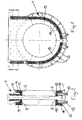
- this is essentially circular Slider housing marked with the reference number 1.
- the slide housing has two coolant flows inside annular sealing seats 2 and 3 in the flow direction have a distance from each other and in radial direction are as narrow as possible in order To minimize heat loss.
- a slide plate serving as a shut-off device can be inserted, which is not shown in the present case.
- This slide plate can be designed as a hollow body and inside with spiral coolant channels be provided by a coolant, in particular by Cooling water can be flowed through.
- the sealing surfaces of the slide plate are very narrow in the radial direction Keep heat losses small.
- the slide plate are of course, associated push rods, by means of which Slide plate from the closed position to the open one Position and vice versa is movable.
- a hood not shown flanged, which is shaped and dimensioned so that it at Open position of the slide plate can accommodate this.
- the narrow sealing seats 2 and 3 of the housing 1 and the also narrow sealing surfaces of the slide plate are all inner surfaces that come into contact with the hot gas provide the device with a fireproof covering.
- the slide plate and the inner wall of the housing with a sufficiently thick layer of a dense and mechanically particularly resistant refractory concrete, namely Heavy concrete 15 lined.
- the not immediately with the hot gas coming in contact inner surfaces, such as. B. the inner surfaces of the hood, not shown, and the further outer areas of the housing 1 and the further inner areas of the shut-off plate are in contrast with a less dense, especially with one of micro and / or macro cavities clad material penetrated, which is not mechanically strong, but one that is special has high thermal insulation.
- this layer exists high thermal insulation from the same basic material as the layers that come into direct contact with the hot gas, namely preferably made of heavy, heavy concrete, which high cold compressive strength of up to 50 MPa distinguished.
- the dense version is the thermal conductivity of fire heavy concrete about 0.8 to 2.0, in particular about 1.5 W / m ° K.
- the trained or immediate near the metal structure to this adjacent layer of refractory cladding possesses thanks to the formation of micro and / or macro cavities a thermal conductivity of approximately 0.08 to 0.20, in particular about 0.16 W / m ° K.
- This thermal conductivity corresponds to approximately half the thermal conductivity of still air. That means the thermal insulation of the mentioned layer is at this example is about twice the size of the thermal insulation still air.
- the macro cavities 14 are distributed approximately uniformly formed directly to the circumferential boundary 13th adjoin the housing metal construction. These macro voids are formed by the fact that before the casting of the Heavy concrete on the inside of the extensive Boundary 13 of the housing 1 polystyrene blocks attached, for. B. be glued. When the heavy concrete is hardening charred the styrofoam blocks with the formation of appropriate Cavities.
- the cavities 14 are with a heat-insulating material, namely microtherm, powder or Granules 12 filled out.
- a heat-insulating material namely microtherm, powder or Granules 12 filled out.
- each cavity with an inlet and outlet opening Mistake.
- a microtherm water suspension passes through the inlet opening filled. Steps through the outlet opening the displaced air from the outside into the environment.
- the layer close to the metal structure of Housing and of course shut-off plate with micro cavities be offset. This can be done by adding plastic particles be obtained when curing or on first use due to the resulting high Thermal decomposition with formation corresponding micro-cavities.
- the Refractory material near the metal structure still with water Reactive particles are added so that these under Gas formation and displacement of water and refractory material Form micro voids.
- the layer comprises a higher layer Thermal insulation close to the metal structure of the housing and / or Barrier cavities in one extent and in one Distribution on so that the thermal conductivity of this layer is approximately 0.08 to 0.20, in particular approximately 0.16 W / m ° K.
- dense fire heavy concrete is a much higher thermal conductivity from about 0.8 to 2.0 W / m ° K, d. H. a much worse one Thermal insulation.
- Lightweight concrete has a much lower one Thermal insulation or higher thermal conductivity of about 0.3 W / m ° K.
- the thermal conductivity of Mikrotherm is about 0.08 W / m ° K.
- Cavities can also contain more or less large pieces of ice or ice cubes, cubes or the like can be used. This are mixed into the refractory material before pouring and when tying it to form the desired ones Cavities consumed.
- the ice content corresponds to about 40 to 60% of the water required for setting.
Landscapes
- Engineering & Computer Science (AREA)
- Chemical & Material Sciences (AREA)
- Manufacturing & Machinery (AREA)
- Materials Engineering (AREA)
- Metallurgy (AREA)
- Organic Chemistry (AREA)
- Building Environments (AREA)
- Control Of Combustion (AREA)
- Temperature-Responsive Valves (AREA)
- Thermal Insulation (AREA)
- Furnace Details (AREA)
- Details Of Valves (AREA)
Description
- Fig. 1
- eine als Heißwindschieber ausgebildete Absperrvorrichtung gemäß der Erfindung in einem Teilschnitt quer zur Strömungsrichtung; und
- Fig. 2
- die in Fig. 1 dargestellte Absperrvorrichtung im Schnitt parallel zur Strömungsrichtung.
Claims (12)
- Absperrvorrichtung für gasförmige Medien hoher Temperatur, insbesondere zur Absperrung der Heißgasleitungen, die von Winderhitzern zu einem Hochofen führen, bestehend ausdadurch gekennzeichnet, daß die Schicht höherer Wärmedämmung aus aushärtbarem Gußmaterial gebildet ist, welches so beschaffen ist, daß sich Mikro- und/oder Makrohohlräume (14) in dem Material der gebildeten Schicht erst beim und/oder nach dem Einbringen des Materials in die Metallkonstruktion (13) ausbilden.einem Gehäuse mit ggf. durch ein Kühlmedium gekühlten Dichtsitzen und einem in dem Gehäuse beweglich angeordneten, ggf. ebenfalls durch ein Kühlmedium gekühlten Absperrorgan,wobei mit Ausnahme der Gehäusedichtsitze (2, 3) und der Dichtflächen am Absperrorgan alle mit dem Heißgas in Berührung kommenden Flächen mit einer feuerfesten, zumindest teilweise zwei- oder mehrschichtigen Verkleidung versehen sind,wobei zwischen der Metallkonstruktion (13) von Gehäuse (1) und/oder Absperrorgan und der mit dem Heißgas in Berührung kommenden Schicht (15) der feuerfesten Verkleidung eine Hohlräume (14) umfassende Schicht höherer Wärmedämmung angeordnet ist,
- Absperrvorrichtung nach Anspruch 1,
dadurch gekennzeichnet, daß die durch Mikro- und/oder Makrohohlräume (14) gekennzeichntete Schicht höherer Wärmedämmung einen in etwa doppelt so hohen Wärmedämmungswert wie ruhende Luft aufweist. - Absperrvorrichtung nach Anspruch 1 oder 2,
dadurch gekennzeichnet, daß die Schicht höherer Wärmedämmung aus dem gleichen Grundmaterial wie die feuerfeste Verkleidung, im übrigen insbesondere die mit dem Heißgas unmittelbar in Berührung kommende Schicht (15), vorzugsweise aus einem Feuerschwerbeton hoher Kaltdruckfestigkeit hergestellt ist. - Absperrvorrichtung nach einem der Ansprüche 1 bis 3,
dadurch gekennzeichnet, daß die Schicht höherer Wärmedämmung eine Wärmeleitfähigkeit von etwa 0,08 - 0,20, insbesondere etwa 0,16 W/m °K aufweist. - Absperrvorrichtung nach einem der Ansprüche 1 bis 4,
dadurch gekennzeichnet, daß die Schicht höherer Wärmedämmung nahe der Metallkonstruktion (13) von Gehäuse (1) und/oder Absperrorgan angeordnet ist, insbesondere unmittelbar an die Metallkonstruktion angrenzend. - Absperrvorrichtung nach Anspruch 5,
dadurch gekennzeichnet, daß die Schicht höherer Wärmedämmung entweder eine Vielzahl von über die Schichtdicke etwa (zufällig) gleichmäßig verteilt ausgebildete Mikro-Hohlräume oder mehrere, insbesondere nahe der Metallkonstruktion (z. B. 13) angeordnete oder unmittelbar an diese angrenzende Hohlräume größerer Abmessung bzw. Makro-Hohlräume (14) aufweist, die etwa gleichmäßig über den Bereich der zu isolierenden Fläche der Metallkonstruktion (z. B. 13) verteilt sind. - Absperrvorrichtung nach einem der vorhergehenden Ansprüche,
dadurch gekennzeichnet, daß die Hohlräume (14) in der Schicht höherer Wärmedämmung durch thermische Zersetzung von in das feuerfeste Material eingebetteten Füllkörpern bei der beim Aushärten der feuerfesten Verkleidung und/oder beim ersten Einsatz der Absperrvorrichtung einwirkenden Temperatur von bis zu 200 °C bzw. bis zu 1300 °C entstehen. - Absperrvorrichtung nach Anspruch 7,
dadurch gekennzeichnet, daß die Füllkörper aus Kunststoff, insbesondere Schaumkunststoff, wie Styropor,, Eisstückchen oder dgl. bestehen. - Absperrvorrichtung nach Anspruch 7,
dadurch gekennzeichnet, daß zur Ausbildung der Schicht höherer Wärmedämmung das Schichtmaterial mit mit Wasser reagierenden Teilchen versetzt ist derart, daß diese unter Gasbildung und Verdrängung von Wasser und Feuerfestmaterial Mikro-Hohlräume bilden. - Absperrvorrichtung nach einem der Ansprüche 1 bis 9,
dadurch gekennzeichnet, daß die Hohlräume in der Schicht höherer Wärmedämmung, insbesondere die dort ausgebildeten Makro-Hohlräume (14) mit Mikrotherm,-Pulver oder -Granulat ausgefüllt sind. - Absperrvorrichtung nach Anspruch 10,
dadurch gekennzeichnet, daß die Makro-Hohlräume jeweils mit einer Einlaß- und Auslaßöffnung versehen sind. - Absperrvorrichtung nach einem der Ansprüche 1 bis 6,
dadurch gekennzeichnet, daß sich die Mikro-Hohlräume (14) in der Schicht höherer Wärmedämmung aufgrund von mit Wasser reagierenden Teilchen im Gußmaterial ausbildet, derart, daß diese Teilchen unter Gasbildung und Verdrängung von Wasser und Material die Mikro-Hohlräume (14) ausbilden.
Applications Claiming Priority (3)
| Application Number | Priority Date | Filing Date | Title |
|---|---|---|---|
| DE19510544A DE19510544C1 (de) | 1995-03-23 | 1995-03-23 | Absperrvorrichtung für Medien hoher Temperatur |
| DE19510544 | 1995-03-23 | ||
| PCT/EP1996/001268 WO1996029434A1 (de) | 1995-03-23 | 1996-03-22 | Absperrvorrichtung für medien hoher temperatur |
Publications (2)
| Publication Number | Publication Date |
|---|---|
| EP0815264A1 EP0815264A1 (de) | 1998-01-07 |
| EP0815264B1 true EP0815264B1 (de) | 1998-10-07 |
Family
ID=7757457
Family Applications (1)
| Application Number | Title | Priority Date | Filing Date |
|---|---|---|---|
| EP96908117A Expired - Lifetime EP0815264B1 (de) | 1995-03-23 | 1996-03-22 | Absperrvorrichtung für medien hoher temperatur |
Country Status (5)
| Country | Link |
|---|---|
| EP (1) | EP0815264B1 (de) |
| JP (1) | JPH10510324A (de) |
| AT (1) | ATE171983T1 (de) |
| DE (2) | DE19510544C1 (de) |
| WO (1) | WO1996029434A1 (de) |
Family Cites Families (6)
| Publication number | Priority date | Publication date | Assignee | Title |
|---|---|---|---|---|
| LU77239A1 (de) * | 1977-05-03 | 1977-08-22 | ||
| US4311166A (en) * | 1980-06-20 | 1982-01-19 | Curtiss-Wright Corporation | Valve assembly for use with high temperature and high pressure fluids |
| SE463513B (sv) * | 1988-07-21 | 1990-12-03 | Eka Nobel Ab | Komposition foer beredning av en vaermeisolerande keramisk belaeggning paa en metall, foerfarande foer dess framstaellning, anvaendning av densamma samt avgasroer foersett med en belaeggning av en saadan komposition |
| JPH0551724A (ja) * | 1991-08-23 | 1993-03-02 | Toyota Motor Corp | 中空溶射層の形成方法 |
| JPH05126295A (ja) * | 1991-11-05 | 1993-05-21 | Fujimori Kogyo Kk | 耐火断熱管及びその製造方法 |
| DE4138283C1 (de) * | 1991-11-21 | 1992-12-10 | Zimmermann & Jansen Gmbh |
-
1995
- 1995-03-23 DE DE19510544A patent/DE19510544C1/de not_active Expired - Lifetime
-
1996
- 1996-03-22 WO PCT/EP1996/001268 patent/WO1996029434A1/de not_active Ceased
- 1996-03-22 JP JP8528098A patent/JPH10510324A/ja active Pending
- 1996-03-22 DE DE59600650T patent/DE59600650D1/de not_active Expired - Fee Related
- 1996-03-22 AT AT96908117T patent/ATE171983T1/de not_active IP Right Cessation
- 1996-03-22 EP EP96908117A patent/EP0815264B1/de not_active Expired - Lifetime
Also Published As
| Publication number | Publication date |
|---|---|
| JPH10510324A (ja) | 1998-10-06 |
| ATE171983T1 (de) | 1998-10-15 |
| WO1996029434A1 (de) | 1996-09-26 |
| DE19510544C1 (de) | 1996-08-08 |
| EP0815264A1 (de) | 1998-01-07 |
| DE59600650D1 (de) | 1998-11-12 |
Similar Documents
| Publication | Publication Date | Title |
|---|---|---|
| DE102004040625B3 (de) | Absperrvorrichtung für gasförmige Medien hoher Temperatur | |
| DE102015013131B4 (de) | Vorrichtung und Verfahren zur Herstellung von aus einem Partikelschaum bestehenden Formteilen | |
| DE1501531A1 (de) | Waermeaustauscherrohr und Waermeaustauscher | |
| CH662086A5 (de) | Verfahren zur herstellung von isolierten rohrleitungsteilen. | |
| DE3910630C2 (de) | ||
| DE2243517C3 (de) | Feuerfeste Wandkonstruktion | |
| EP0815264B1 (de) | Absperrvorrichtung für medien hoher temperatur | |
| DE2552637A1 (de) | Plattenkuehler fuer schachtofen, insbesondere hochofen, und verfahren zur dessen ausfuehrung | |
| EP0289491A1 (de) | Schichtenweise aufgebauter wärmedamm. | |
| DE4138283C1 (de) | ||
| DE2824906A1 (de) | Verfahren zur herstellung von waermeisolierten leitungsrohren | |
| DE2830687A1 (de) | Im boden verlegte, waermeisolierte metallische rohrleitung | |
| DE2338337B2 (de) | Kernreaktoranlage | |
| DE2318817A1 (de) | Vorrichtung zum giessen von geschmolzenem metall und arbeitsverfahren zur betaetigung der vorrichtung | |
| DE2100528C3 (de) | Hitzebeständiges und wärmeisolierendes Rohr | |
| DE1965849A1 (de) | Waermeisolierung fuer Spannbetondruckbehaelter,insbesondere fuer Atomkernreaktoren | |
| DE3615457A1 (de) | Giessvorrichtung fuer vorgeschaeumtes polystyrol | |
| CH247647A (de) | Wand-, Decken- oder Boden-Heiz- bezw. -Kühleinrichtung. | |
| DE661626C (de) | Metallkokille, insbesondere fuer Schleuderguss | |
| DE2905593A1 (de) | Druckbehaelter fuer heisse medien | |
| AT299776B (de) | Verfahren zur Herstellen eines Formstückes für Kamine und nach diesem Verfahren hergestelltes Formstück | |
| DE2813678A1 (de) | Ofenwand fuer hohe temperaturen | |
| DE2716078A1 (de) | Isolier- und einbettungsmasse, damit umhuelltes fernheizleitungsrohr und verfahren zu seiner herstellung | |
| DE19707915A1 (de) | Verbindung eines heißen, ungekühlten Rohres mit einem gekühlten Rohr | |
| DE3333508A1 (de) | Vorgefertigter isolierkoerper |
Legal Events
| Date | Code | Title | Description |
|---|---|---|---|
| PUAI | Public reference made under article 153(3) epc to a published international application that has entered the european phase |
Free format text: ORIGINAL CODE: 0009012 |
|
| 17P | Request for examination filed |
Effective date: 19970917 |
|
| AK | Designated contracting states |
Kind code of ref document: A1 Designated state(s): AT BE DE FI FR GB IT NL PT |
|
| GRAG | Despatch of communication of intention to grant |
Free format text: ORIGINAL CODE: EPIDOS AGRA |
|
| GRAG | Despatch of communication of intention to grant |
Free format text: ORIGINAL CODE: EPIDOS AGRA |
|
| GRAH | Despatch of communication of intention to grant a patent |
Free format text: ORIGINAL CODE: EPIDOS IGRA |
|
| 17Q | First examination report despatched |
Effective date: 19980220 |
|
| GRAH | Despatch of communication of intention to grant a patent |
Free format text: ORIGINAL CODE: EPIDOS IGRA |
|
| GRAA | (expected) grant |
Free format text: ORIGINAL CODE: 0009210 |
|
| AK | Designated contracting states |
Kind code of ref document: B1 Designated state(s): AT BE DE FI FR GB IT NL PT |
|
| REF | Corresponds to: |
Ref document number: 171983 Country of ref document: AT Date of ref document: 19981015 Kind code of ref document: T |
|
| REF | Corresponds to: |
Ref document number: 59600650 Country of ref document: DE Date of ref document: 19981112 |
|
| GBT | Gb: translation of ep patent filed (gb section 77(6)(a)/1977) |
Effective date: 19981103 |
|
| ET | Fr: translation filed | ||
| REG | Reference to a national code |
Ref country code: PT Ref legal event code: SC4A Free format text: AVAILABILITY OF NATIONAL TRANSLATION Effective date: 19990105 |
|
| PLBE | No opposition filed within time limit |
Free format text: ORIGINAL CODE: 0009261 |
|
| STAA | Information on the status of an ep patent application or granted ep patent |
Free format text: STATUS: NO OPPOSITION FILED WITHIN TIME LIMIT |
|
| 26N | No opposition filed | ||
| REG | Reference to a national code |
Ref country code: GB Ref legal event code: IF02 |
|
| PGFP | Annual fee paid to national office [announced via postgrant information from national office to epo] |
Ref country code: GB Payment date: 20030224 Year of fee payment: 8 |
|
| PGFP | Annual fee paid to national office [announced via postgrant information from national office to epo] |
Ref country code: PT Payment date: 20030310 Year of fee payment: 8 |
|
| PGFP | Annual fee paid to national office [announced via postgrant information from national office to epo] |
Ref country code: NL Payment date: 20030317 Year of fee payment: 8 |
|
| PGFP | Annual fee paid to national office [announced via postgrant information from national office to epo] |
Ref country code: FR Payment date: 20030318 Year of fee payment: 8 |
|
| PGFP | Annual fee paid to national office [announced via postgrant information from national office to epo] |
Ref country code: AT Payment date: 20030321 Year of fee payment: 8 |
|
| PGFP | Annual fee paid to national office [announced via postgrant information from national office to epo] |
Ref country code: FI Payment date: 20030324 Year of fee payment: 8 |
|
| PGFP | Annual fee paid to national office [announced via postgrant information from national office to epo] |
Ref country code: BE Payment date: 20030326 Year of fee payment: 8 |
|
| PGFP | Annual fee paid to national office [announced via postgrant information from national office to epo] |
Ref country code: DE Payment date: 20030527 Year of fee payment: 8 |
|
| PG25 | Lapsed in a contracting state [announced via postgrant information from national office to epo] |
Ref country code: GB Free format text: LAPSE BECAUSE OF NON-PAYMENT OF DUE FEES Effective date: 20040322 Ref country code: FI Free format text: LAPSE BECAUSE OF NON-PAYMENT OF DUE FEES Effective date: 20040322 Ref country code: AT Free format text: LAPSE BECAUSE OF NON-PAYMENT OF DUE FEES Effective date: 20040322 |
|
| PG25 | Lapsed in a contracting state [announced via postgrant information from national office to epo] |
Ref country code: BE Free format text: LAPSE BECAUSE OF NON-PAYMENT OF DUE FEES Effective date: 20040331 |
|
| BERE | Be: lapsed |
Owner name: *ZIMMERMANN & JANSEN G.M.B.H. Effective date: 20040331 |
|
| PG25 | Lapsed in a contracting state [announced via postgrant information from national office to epo] |
Ref country code: NL Free format text: LAPSE BECAUSE OF NON-PAYMENT OF DUE FEES Effective date: 20041001 Ref country code: DE Free format text: LAPSE BECAUSE OF NON-PAYMENT OF DUE FEES Effective date: 20041001 |
|
| PG25 | Lapsed in a contracting state [announced via postgrant information from national office to epo] |
Ref country code: PT Free format text: LAPSE BECAUSE OF NON-PAYMENT OF DUE FEES Effective date: 20041015 |
|
| GBPC | Gb: european patent ceased through non-payment of renewal fee |
Effective date: 20040322 |
|
| PG25 | Lapsed in a contracting state [announced via postgrant information from national office to epo] |
Ref country code: FR Free format text: LAPSE BECAUSE OF NON-PAYMENT OF DUE FEES Effective date: 20041130 |
|
| REG | Reference to a national code |
Ref country code: PT Ref legal event code: MM4A Free format text: LAPSE DUE TO NON-PAYMENT OF FEES Effective date: 20040930 |
|
| NLV4 | Nl: lapsed or anulled due to non-payment of the annual fee |
Effective date: 20041001 |
|
| REG | Reference to a national code |
Ref country code: FR Ref legal event code: ST |
|
| PG25 | Lapsed in a contracting state [announced via postgrant information from national office to epo] |
Ref country code: IT Free format text: LAPSE BECAUSE OF NON-PAYMENT OF DUE FEES;WARNING: LAPSES OF ITALIAN PATENTS WITH EFFECTIVE DATE BEFORE 2007 MAY HAVE OCCURRED AT ANY TIME BEFORE 2007. THE CORRECT EFFECTIVE DATE MAY BE DIFFERENT FROM THE ONE RECORDED. Effective date: 20050322 |