EP0814975B1 - Verbindungseinheit mit extrudierter dichtung - Google Patents
Verbindungseinheit mit extrudierter dichtung Download PDFInfo
- Publication number
- EP0814975B1 EP0814975B1 EP97901136A EP97901136A EP0814975B1 EP 0814975 B1 EP0814975 B1 EP 0814975B1 EP 97901136 A EP97901136 A EP 97901136A EP 97901136 A EP97901136 A EP 97901136A EP 0814975 B1 EP0814975 B1 EP 0814975B1
- Authority
- EP
- European Patent Office
- Prior art keywords
- fixing flange
- elastomer
- anchoring
- assembly element
- element according
- Prior art date
- Legal status (The legal status is an assumption and is not a legal conclusion. Google has not performed a legal analysis and makes no representation as to the accuracy of the status listed.)
- Expired - Lifetime
Links
- 229920001971 elastomer Polymers 0.000 claims abstract description 30
- 239000000806 elastomer Substances 0.000 claims abstract description 29
- 238000004873 anchoring Methods 0.000 claims abstract description 21
- 239000000853 adhesive Substances 0.000 claims abstract description 7
- 230000001070 adhesive effect Effects 0.000 claims abstract description 6
- 238000001125 extrusion Methods 0.000 claims description 21
- 238000007789 sealing Methods 0.000 claims description 16
- 239000002184 metal Substances 0.000 claims description 9
- 239000011324 bead Substances 0.000 claims description 5
- 238000011065 in-situ storage Methods 0.000 claims description 5
- 239000000463 material Substances 0.000 claims description 4
- 239000003795 chemical substances by application Substances 0.000 claims description 3
- 238000000465 moulding Methods 0.000 claims description 3
- 229920001169 thermoplastic Polymers 0.000 claims description 3
- 239000004416 thermosoftening plastic Substances 0.000 claims description 3
- 229920002943 EPDM rubber Polymers 0.000 claims description 2
- 239000004743 Polypropylene Substances 0.000 claims description 2
- -1 polypropylene Polymers 0.000 claims description 2
- 229920001155 polypropylene Polymers 0.000 claims description 2
- 238000004381 surface treatment Methods 0.000 claims description 2
- 230000008021 deposition Effects 0.000 claims 1
- 229920000642 polymer Polymers 0.000 claims 1
- 229920000098 polyolefin Polymers 0.000 claims 1
- 238000000034 method Methods 0.000 description 8
- 230000008439 repair process Effects 0.000 description 4
- 239000000758 substrate Substances 0.000 description 4
- 230000007704 transition Effects 0.000 description 2
- 238000004026 adhesive bonding Methods 0.000 description 1
- 210000003323 beak Anatomy 0.000 description 1
- 230000009286 beneficial effect Effects 0.000 description 1
- 239000013536 elastomeric material Substances 0.000 description 1
- 239000011521 glass Substances 0.000 description 1
- 230000008595 infiltration Effects 0.000 description 1
- 238000001764 infiltration Methods 0.000 description 1
- 230000002045 lasting effect Effects 0.000 description 1
- 238000004519 manufacturing process Methods 0.000 description 1
- 229920001296 polysiloxane Polymers 0.000 description 1
- 229920003031 santoprene Polymers 0.000 description 1
- 238000009991 scouring Methods 0.000 description 1
- 238000000926 separation method Methods 0.000 description 1
- 239000007787 solid Substances 0.000 description 1
- 229920002725 thermoplastic elastomer Polymers 0.000 description 1
- XLYOFNOQVPJJNP-UHFFFAOYSA-N water Substances O XLYOFNOQVPJJNP-UHFFFAOYSA-N 0.000 description 1
- 238000004078 waterproofing Methods 0.000 description 1
Images

Classifications
-
- B—PERFORMING OPERATIONS; TRANSPORTING
- B60—VEHICLES IN GENERAL
- B60J—WINDOWS, WINDSCREENS, NON-FIXED ROOFS, DOORS, OR SIMILAR DEVICES FOR VEHICLES; REMOVABLE EXTERNAL PROTECTIVE COVERINGS SPECIALLY ADAPTED FOR VEHICLES
- B60J10/00—Sealing arrangements
- B60J10/80—Sealing arrangements specially adapted for opening panels, e.g. doors
- B60J10/84—Sealing arrangements specially adapted for opening panels, e.g. doors arranged on the vehicle body
-
- B—PERFORMING OPERATIONS; TRANSPORTING
- B60—VEHICLES IN GENERAL
- B60J—WINDOWS, WINDSCREENS, NON-FIXED ROOFS, DOORS, OR SIMILAR DEVICES FOR VEHICLES; REMOVABLE EXTERNAL PROTECTIVE COVERINGS SPECIALLY ADAPTED FOR VEHICLES
- B60J10/00—Sealing arrangements
- B60J10/80—Sealing arrangements specially adapted for opening panels, e.g. doors
- B60J10/86—Sealing arrangements specially adapted for opening panels, e.g. doors arranged on the opening panel
Definitions
- the present invention relates to an object equipped with an elastomer cord by in situ extrusion and more particularly an assembly element which has a fixing flange to which the elastomeric cord intended is fixed in particular to constitute a seal between the object which it equips and another object in relation to which it can move.
- Document EP-A-0 524 092 describes a technique for equipping an object of a profiled bead extruded in situ.
- the cord is made of elastomer and can equip various objects, automotive glass and various automotive parts, such as doors, hoods or casing, door or window or glazing intended for the building as well as door or parts of household appliance.
- the elastomer cord is attached to the object by gluing, this being carried out thanks to the choice of the elastomer and to the treatment from the surface of the object.
- connection is improved by the presence of holes in the element assembly, through which the material of the joint penetrates for fixing solid and definitive.
- the invention firstly aims to prepare an assembly element having an extruded seal which. if necessary, could be simply removed from the assembly element and later reused on it same item.
- the invention proposes an assembly element fitted with an elastomeric bead by in situ extrusion on a fixing flange the element, in which the fixing flange is provided with anchoring notches or anchoring projections in intimate contact from which the elastomer material has penetrated.
- the elastomer and the fixing flange do not form no adhesive bond and the notches or the anchoring projections have a undercut limited so as to achieve a purely mechanical anchoring which allows the elastomeric cord to be detached from the fixing flange and to be subsequently fixed again.
- the characteristics of the invention therefore make it possible to conserve the process economical extrusion of sealing profiles and avoid at the same time disadvantages associated with it so far, in the sense that, on the one hand, we can detach them. if necessary, the body element and reuse them later. This is made possible by the fact that the adhesive bond which was performed so far during extrusion is replaced by a mechanical connection appropriate.
- a profile of interlocking sealing it does not substantially present the drawbacks associated to known interlocking profiles.
- it adapts ideally to the shape of the fixing flange and guarantees in this way an absolute seal against water infiltration between the sealing profile and fixing flange.
- the elastomer used for the extrusion and / or the surface of the flange fasteners are such as not to stick to each other. This can be achieved, for example, by choosing an appropriate elastomer, which does not adhere, as as such, on the surface of the fixing flange. Adhesion can also be avoided by an appropriate surface treatment of the fixing flange, for example by the deposit of an appropriate separation agent. Notches and / or projections performing mechanical anchoring at the fixing flange can be formed in principle in any way, as long as they allow mechanically detach the profiled sealing rod and reinsert it.
- the extrusion die and the fixing flange must be formed of so that the scoured hollows, which are formed by the anchoring projections or the anchoring notches are filled during the extrusion operation.
- the invention is shown used for door seals, but it is, of course, not limited to this application. It can be used, in principle, with the same advantage for trunk covers, hoods and other movable body parts, and also in other areas, where profiles are used waterproofing as in building or household appliances.
- Figure 1 shows the lower section of an automobile door 1 and the base 2 of the vehicle floor which cooperates with the door 1.
- the watertightness between the door and the base is ensured by the two sealing profiles 5 and 10.
- the sealing profile 5 was produced by direct extrusion of an elastomer on the fixing rim 6 of the base 2, and the sealing profile 10 by direct extrusion of the elastomer on the edge 11 on the door and on the fixing edge 12.
- Thermoplastic elastomers have proven themselves for the manufacture of extruded sealing profiles, in particular polyolefins-elastomers thermoplastics made of isotactic polypropylene and ethylene-propylene-diene rubber, for example available products commercially known as SANTOPRENE. These elastomers thermoplastics have an operating temperature of 180 to 230 ° C, so that the extruder as well as the extrusion die and the flexible connection between the extruder and the extrusion die should be heated to corresponding way.
- the elastomers produced on this basis have however also the characteristic that they do not adhere well to the substrate, on which they are extruded, only when the surface of this substrate is treated with a suitable adhesive agent. This poor adhesion is advantageous for the method of the invention. However, if applicable, it may be beneficial to completely prevent adhesion, to treat the surface of the substrate using an appropriate separating agent, for example using a solution containing silicone.
- the necessary anchoring projections or anchoring notches in the fixing flanges can be made in different ways. It is thus, for example possible, to spare in the fixing flange, in the direction longitudinal, a groove with scouring, a molding or a fold, the cross section is each time formed so that, on the one hand, the anchoring function is fulfilled and that, on the other hand, the removal of the profile and its reinsertion are possible.
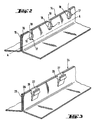
- FIG. 2 and 3 Appropriate embodiments for the configuration of the flange fastening are shown in Figures 2 and 3.
- the figures show the fixing flanges 14 and 24, which correspond to the fixing flange 6, on the FIG. 1.
- the fixing flange 14, which is formed by the two sheet metal strips 15, 16 folded and welded to each other, is provided at its upper edge notches 17, which are, for example, produced by stamping.
- the notches 17 consist in the case shown of an opening 18, for example round and a cut 19 connecting the opening 18 to the upper side of the flange of fixation.
- the fixing flange is covered by the elastomer beyond the openings 18, approximately up to the line A-A.
- the highly viscous elastomer therefore penetrates into the openings 18 and in cuts 19.
- the bead profile thus formed can be removed from the fixing flange and be subsequently reattached to the fixing flange, the connecting bars 20 formed during the extrusion inside the openings 18 and the cuts 19 are then reintroduced into the corresponding notches 17 between the two wings 21 and 22 of the sealing profile 5 ( Figure 1).
- the fixing flange 24 is again formed by two strips of sheet metal 25 and 26 folded.
- the notches required for mechanical anchoring are formed by the fact that, in sheet metal strips 26, at distances of par example 5 to 20 cm, small sheet metal segments 27 at the edge are bent and folded outwards in the form of beaks using a stamping tool appropriate.
- These sheet metal segments 27 are provided, in the same operation stamping, a molding 28, which each time forms anchoring projections for the elastomeric material both on the inner side, i.e. inside the housing formed by the folded sheet metal segment 27 and the sheet metal strip 25, outer side of the sheet metal segments 27.
- the invention allows disassembly then reassembly of an elastomer cord, and contributes to the control of the connection an extruded joint in situ with its support.
Landscapes
- Engineering & Computer Science (AREA)
- Mechanical Engineering (AREA)
- Seal Device For Vehicle (AREA)
- Extrusion Moulding Of Plastics Or The Like (AREA)
- Gasket Seals (AREA)
Claims (6)
- Verbindungselement mit einem durch Extrusion in situ an einen Befestigungsflansch des Elements angebrachten Elastomerstrang, dadurch gekennzeichnet, dass der Befestigungsflansch (6, 12, 14, 24) mit Verankerungsausnehmungen (17) und/oder Verankerungsvorsprüngen (27, 28) versehen ist, dass das Elastomer und die Oberfläche des Befestigungsflansches (6, 12, 14, 24) keine adhäsive Bindung miteinander eingehen, und dass die Verankerungsausnehmungen (17) und/oder die Verankerungsvorsprünge (27, 28) eine begrenzte Hinterschneidung haben, so dass eine lediglich mechanische Verankerung gebildet wird, welche es erlaubt, das Dichtungsprofil (5, 10) vom Befestigungsflansch (6, 12, 14, 24) zu lösen und es später wieder daran zu befestigen.
- Verbindungselement nach Anspruch 1, dadurch gekennzeichnet, dass die Verankerungsausnehmungen (17) eines Befestigungsflansches (14) aus Randeinschnitten (19) und sich daran anschließenden etwa kreisförmigen Löchern (18) bestehen, in die die beim Anextrudieren entstandenen Verbindungsstege (20) zwischen den Schenkeln (21, 22) des den Befestigungsflansch (6) übergreifenden Abschnitts des Dichtprofils (5) später wieder einknüpfbar sind.
- Verbindungselement nach Anspruch 1, dadurch gekennzeichnet, dass die Verankerungsvorsprünge aus abgekröpften, mit Sicken (28) versehenen Blechabschnitten (27) bestehen.
- Verbindungselement nach einem der vorstehenden Ansprüche 1 bis 3, dadurch gekennzeichnet, dass das Mittel zum Verhindern einer adhäsiven Verbindung zwischen dem Elastomer und dem Befestigungsflansch (6, 12, 14, 24) eine Behandlung der Oberfläche des Befestigungsflanschs, insbesondere eine Beschichtung mit einem Trennmittel ist.
- Verbindungselement nach einem der vorstehenden Ansprüche 1 bis 3, dadurch gekennzeichnet, dass das Mittel zum Verhindern einer adhäsiven Verbindung zwischen dem Elastomer und dem Befestigungsflansch (6, 12, 14, 24) die Auswahl eines nicht an der Oberfläche des Befestigungsflanschs haftenden Polymers ist.
- Verbindungselement nach Anspruch 5, dadurch gekennzeichnet, dass das besagte Elastomer ein thermoplastisches Polyolefin-Elastomer aus isotaktischem Polypropylen und Ethylen-Propylen-Dien-Kautschuk ist.
Applications Claiming Priority (3)
| Application Number | Priority Date | Filing Date | Title |
|---|---|---|---|
| DE19602245A DE19602245C2 (de) | 1996-01-23 | 1996-01-23 | Karosserieteil mit anextrudierter Dichtung |
| DE19602245 | 1996-01-23 | ||
| PCT/FR1997/000118 WO1997027081A1 (fr) | 1996-01-23 | 1997-01-22 | Element d'assemblage a joint d'etancheite extrude |
Publications (2)
| Publication Number | Publication Date |
|---|---|
| EP0814975A1 EP0814975A1 (de) | 1998-01-07 |
| EP0814975B1 true EP0814975B1 (de) | 2001-12-05 |
Family
ID=7783416
Family Applications (1)
| Application Number | Title | Priority Date | Filing Date |
|---|---|---|---|
| EP97901136A Expired - Lifetime EP0814975B1 (de) | 1996-01-23 | 1997-01-22 | Verbindungseinheit mit extrudierter dichtung |
Country Status (9)
| Country | Link |
|---|---|
| US (1) | US6243990B1 (de) |
| EP (1) | EP0814975B1 (de) |
| JP (1) | JPH11502488A (de) |
| CN (1) | CN1077521C (de) |
| DE (2) | DE19602245C2 (de) |
| ES (1) | ES2166970T3 (de) |
| MX (1) | MX9706782A (de) |
| PT (1) | PT814975E (de) |
| WO (1) | WO1997027081A1 (de) |
Families Citing this family (18)
| Publication number | Priority date | Publication date | Assignee | Title |
|---|---|---|---|---|
| DE19843597C1 (de) * | 1998-09-23 | 2000-03-09 | Goldbach Innenausbau Gmbh | Profilständer, insbesondere für Raum-Trennwände und Verfahren zum Herstellen von Ständer-Profilschienen |
| DE29903684U1 (de) * | 1999-03-02 | 2000-03-30 | Meteor Gummiwerke K. H. Bädje GmbH & Co, 31167 Bockenem | Auf einen Halteflansch aufsteckbares Dichtungsprofil |
| DE29909469U1 (de) | 1999-05-21 | 1999-08-05 | Brose Fahrzeugteile GmbH & Co. KG, Coburg, 96450 Coburg | Trägerelement für eine Kraftfahrzeugtür |
| DE10042439B4 (de) * | 2000-08-30 | 2004-07-08 | Bayerische Motoren Werke Ag | Tragflansch eines Kraftfahrzeugs für eine aufsteckbare Dichtung |
| JP2003159948A (ja) * | 2001-11-26 | 2003-06-03 | Nishikawa Rubber Co Ltd | スライド式リヤドア用ウエザーストリップの型成形部の構造 |
| DE10158957B4 (de) * | 2001-12-03 | 2005-10-27 | Webasto Ag | Deckel für eine Fahrzeug-Dachöffnung sowie Verfahren zur Herstellung eines Deckels |
| DE102004053622A1 (de) * | 2004-11-03 | 2006-05-04 | Faurecia Innenraum Systeme Gmbh | Verfahren zur Herstellung eines Tür- oder Seitenwandmoduls |
| US7552520B2 (en) * | 2005-06-13 | 2009-06-30 | Dayco Products, Llc | Extruded seal having a corrugated axial surface, a method of manufacturing such seals, and a method of using such seals |
| US7479316B2 (en) * | 2005-06-13 | 2009-01-20 | Dayco Products, Llc | Extruded binary seal |
| DE102006010824A1 (de) * | 2006-03-07 | 2007-10-25 | Gepoc Verfahrenstechnik Gmbh | Träger mit einer Dichtung |
| US8623251B2 (en) * | 2006-07-12 | 2014-01-07 | Parker-Hannifin Corporation | Extruded and configured lathe-cut packer elements |
| KR100786889B1 (ko) * | 2006-10-31 | 2007-12-17 | 기아자동차주식회사 | 자동차용 루프 몰딩의 커버구조 |
| US9745794B2 (en) * | 2013-09-16 | 2017-08-29 | Jeffrey S. Ellingson | Apparatus for sealing door of an enclosure |
| DE102013223355B4 (de) * | 2013-11-15 | 2015-09-17 | Bayerische Motoren Werke Aktiengesellschaft | Verfahren zur Herstellung eines Fahrzeugaußenhautelements |
| JP6527018B2 (ja) * | 2015-05-19 | 2019-06-05 | 西川ゴム工業株式会社 | 車両用シール材の取付構造 |
| DE202016002146U1 (de) * | 2016-04-01 | 2017-07-06 | GM Global Technology Operations LLC (n. d. Gesetzen des Staates Delaware) | Kunststoff-Panelelement zur Anordnung an einer Kraftfahrzeugstirnwand |
| JP7396033B2 (ja) * | 2019-12-25 | 2023-12-12 | 株式会社アイシン | 車両用開口部のシール構造 |
| JP7705782B2 (ja) * | 2021-10-29 | 2025-07-10 | トヨタ紡織株式会社 | 乗物用床構造 |
Family Cites Families (12)
| Publication number | Priority date | Publication date | Assignee | Title |
|---|---|---|---|---|
| GB631890A (en) * | 1947-02-18 | 1949-11-11 | Thomas John Robert Bright | Improvements in draught excluding strips, beadings, mouldings, and the like |
| GB655268A (en) * | 1948-01-30 | 1951-07-18 | Thomas John Robert Bright | Improvements in draught excluding strips |
| GB670785A (en) * | 1949-01-31 | 1952-04-23 | Weld O Welt Corp | Improvements in or relating to a sealing strip |
| US2679667A (en) * | 1949-03-26 | 1954-06-01 | Eagle Picher Co | Sealing strip |
| US2968072A (en) * | 1951-07-18 | 1961-01-17 | Bright Thomas John Robert | Draught excluding strips, beadings, mouldings or the like |
| DE1900101U (de) * | 1964-06-05 | 1964-09-03 | Happich Gmbh Gebr | Profilierter streifen. |
| DE3833887A1 (de) * | 1988-10-05 | 1990-04-12 | Bayerische Motoren Werke Ag | Gummielastische dichtung |
| CN2074805U (zh) * | 1990-05-29 | 1991-04-10 | 北京市潞州钢窗厂 | 新式防火门 |
| DE4123588A1 (de) | 1991-07-17 | 1993-01-21 | Ver Glaswerke Gmbh | Verfahren und vorrichtung zur herstellung eines fahrzeugfensters |
| US5261721A (en) * | 1991-10-18 | 1993-11-16 | Donnelly Corporation | Vehicular window assembly with weather seal |
| DE4441852A1 (de) * | 1994-11-24 | 1996-05-30 | Bayerische Motoren Werke Ag | An einem Tragteil vorgesehene gummielastische Profilleiste |
| US5613327A (en) * | 1995-02-24 | 1997-03-25 | Chrysler Corporation | Door sill garnish trim |
-
1996
- 1996-01-23 DE DE19602245A patent/DE19602245C2/de not_active Expired - Fee Related
-
1997
- 1997-01-22 PT PT97901136T patent/PT814975E/pt unknown
- 1997-01-22 MX MX9706782A patent/MX9706782A/es not_active IP Right Cessation
- 1997-01-22 WO PCT/FR1997/000118 patent/WO1997027081A1/fr not_active Ceased
- 1997-01-22 ES ES97901136T patent/ES2166970T3/es not_active Expired - Lifetime
- 1997-01-22 DE DE69708758T patent/DE69708758T2/de not_active Expired - Fee Related
- 1997-01-22 CN CN97190186A patent/CN1077521C/zh not_active Expired - Fee Related
- 1997-01-22 EP EP97901136A patent/EP0814975B1/de not_active Expired - Lifetime
- 1997-01-22 JP JP9526598A patent/JPH11502488A/ja not_active Withdrawn
- 1997-01-22 US US08/913,482 patent/US6243990B1/en not_active Expired - Fee Related
Also Published As
| Publication number | Publication date |
|---|---|
| DE69708758T2 (de) | 2002-08-08 |
| DE19602245A1 (de) | 1997-07-24 |
| CN1181731A (zh) | 1998-05-13 |
| EP0814975A1 (de) | 1998-01-07 |
| JPH11502488A (ja) | 1999-03-02 |
| DE19602245C2 (de) | 1999-01-28 |
| DE69708758D1 (de) | 2002-01-17 |
| US6243990B1 (en) | 2001-06-12 |
| ES2166970T3 (es) | 2002-05-01 |
| PT814975E (pt) | 2002-04-29 |
| CN1077521C (zh) | 2002-01-09 |
| WO1997027081A1 (fr) | 1997-07-31 |
| MX9706782A (es) | 1997-11-29 |
Similar Documents
| Publication | Publication Date | Title |
|---|---|---|
| EP0814975B1 (de) | Verbindungseinheit mit extrudierter dichtung | |
| EP1324892B1 (de) | Verwendung von verglasung mit einem profiliertem band zu seiner installation in einer öffnung | |
| EP0248707B1 (de) | Mit einer einsteckbaren Randleiste versehene Fensterscheibe | |
| EP0729857B1 (de) | Glasscheibe, insbesondere für Kraftfahrzeuge, prepariert zum Montieren durch Klebung | |
| CA1319944C (fr) | Vitrage pourvu d'un joint d'etancheite profile elastique, en particulier vitrage d'automobile | |
| EP0209453B1 (de) | Verfahren zur Herstellung von Profilen durch Koextrusion, die mindestens zwei Teile mit verschiedenen Eigenschaften haben | |
| EP1240041B1 (de) | Anfügen einer autoscheibe an ein anschlusselement | |
| FR2577484A1 (fr) | Volet rigide, notamment en verre, avec cadre de renforcement et joint d'etancheite pour toit ouvrant de vehicule | |
| FR2589513A1 (fr) | Bloc fenetre, notamment pour vehicule, et procede et moule pour sa production | |
| EP0119906A1 (de) | Dichtungsstreifen zum Einbau einer Sicherheitsscheibe in eine Öffnung, insbesondere einer Windschutzscheibe eines Kraftfahrzeuges | |
| EP0307317A2 (de) | Kraftfahrzeugfenster | |
| EP0128837B1 (de) | Fertig einsetzbare Glasscheibe, insbesondere für Kraftfahrzeuge | |
| FR2633570A1 (fr) | Lecheur de bas de glace mobile de vehicule automobile | |
| FR2543533A1 (fr) | Montage par collage de vitrages dans une baie, notamment de pare-brise pour vehicules automobiles, facilitant leur demontage | |
| EP1034085B1 (de) | Verglasung mit einem profilierten band, das mit einem abdeckungsansatz versehen ist | |
| EP0537067B1 (de) | Fahrzeugverglasung mit einem vorgefertigten elastomerischen Formteil | |
| FR2834937A1 (fr) | Joint de garniture pour vitre fixe solidarisee aux rebords d'une ouverture et procede de fabrication de celui-ci | |
| CA2443727C (fr) | Vitre de fenetre collable avec cordon de dechirure | |
| FR2540212A1 (fr) | Joint pour pieces en tole, notamment pour coffres et portes de vehicules | |
| EP0795431A1 (de) | Zur Verklebung vorgefertigte Fahrzeugverglasung und Herstellungsverfahren | |
| EP1080967B1 (de) | Mit einer starren Armierung versehene U-förmige Profildichtung aus Elastomer oder Plastomer | |
| EP0834639A1 (de) | Vorrichtung für die Montage einer Verglasung in einem Tragrahm für eine Tür, ein Fenster oder ähnliches | |
| EP0938995A1 (de) | Dichtungselement für Schiebefenster, insbesondere für eine Kraftfahrzeugtür und Verfahren zu deren Herstellung | |
| FR2569810A1 (fr) | Joints d'etancheite notamment pour menuiserie et huisserie, et leur procede de fabrication | |
| FR2643125A1 (fr) | Procede de fabrication d'un joint d'etancheite pour surface mobile et joint obtenu par ce procede |
Legal Events
| Date | Code | Title | Description |
|---|---|---|---|
| PUAI | Public reference made under article 153(3) epc to a published international application that has entered the european phase |
Free format text: ORIGINAL CODE: 0009012 |
|
| 17P | Request for examination filed |
Effective date: 19970906 |
|
| AK | Designated contracting states |
Kind code of ref document: A1 Designated state(s): BE DE ES FR GB IT NL PT SE |
|
| 17Q | First examination report despatched |
Effective date: 19990217 |
|
| GRAG | Despatch of communication of intention to grant |
Free format text: ORIGINAL CODE: EPIDOS AGRA |
|
| GRAG | Despatch of communication of intention to grant |
Free format text: ORIGINAL CODE: EPIDOS AGRA |
|
| GRAH | Despatch of communication of intention to grant a patent |
Free format text: ORIGINAL CODE: EPIDOS IGRA |
|
| RAP1 | Party data changed (applicant data changed or rights of an application transferred) |
Owner name: SAINT-GOBAIN GLASS FRANCE |
|
| GRAH | Despatch of communication of intention to grant a patent |
Free format text: ORIGINAL CODE: EPIDOS IGRA |
|
| GRAA | (expected) grant |
Free format text: ORIGINAL CODE: 0009210 |
|
| AK | Designated contracting states |
Kind code of ref document: B1 Designated state(s): BE DE ES FR GB IT NL PT SE |
|
| REG | Reference to a national code |
Ref country code: GB Ref legal event code: IF02 |
|
| REF | Corresponds to: |
Ref document number: 69708758 Country of ref document: DE Date of ref document: 20020117 |
|
| GBT | Gb: translation of ep patent filed (gb section 77(6)(a)/1977) |
Effective date: 20020131 |
|
| REG | Reference to a national code |
Ref country code: PT Ref legal event code: SC4A Free format text: AVAILABILITY OF NATIONAL TRANSLATION Effective date: 20020121 |
|
| REG | Reference to a national code |
Ref country code: ES Ref legal event code: FG2A Ref document number: 2166970 Country of ref document: ES Kind code of ref document: T3 |
|
| PLBE | No opposition filed within time limit |
Free format text: ORIGINAL CODE: 0009261 |
|
| STAA | Information on the status of an ep patent application or granted ep patent |
Free format text: STATUS: NO OPPOSITION FILED WITHIN TIME LIMIT |
|
| 26N | No opposition filed | ||
| PGFP | Annual fee paid to national office [announced via postgrant information from national office to epo] |
Ref country code: PT Payment date: 20031230 Year of fee payment: 8 |
|
| PGFP | Annual fee paid to national office [announced via postgrant information from national office to epo] |
Ref country code: SE Payment date: 20040107 Year of fee payment: 8 |
|
| PGFP | Annual fee paid to national office [announced via postgrant information from national office to epo] |
Ref country code: FR Payment date: 20040114 Year of fee payment: 8 |
|
| PGFP | Annual fee paid to national office [announced via postgrant information from national office to epo] |
Ref country code: NL Payment date: 20040121 Year of fee payment: 8 Ref country code: GB Payment date: 20040121 Year of fee payment: 8 |
|
| PGFP | Annual fee paid to national office [announced via postgrant information from national office to epo] |
Ref country code: ES Payment date: 20040123 Year of fee payment: 8 |
|
| PGFP | Annual fee paid to national office [announced via postgrant information from national office to epo] |
Ref country code: DE Payment date: 20040203 Year of fee payment: 8 |
|
| PGFP | Annual fee paid to national office [announced via postgrant information from national office to epo] |
Ref country code: BE Payment date: 20040217 Year of fee payment: 8 |
|
| PG25 | Lapsed in a contracting state [announced via postgrant information from national office to epo] |
Ref country code: IT Free format text: LAPSE BECAUSE OF NON-PAYMENT OF DUE FEES Effective date: 20050122 Ref country code: GB Free format text: LAPSE BECAUSE OF NON-PAYMENT OF DUE FEES Effective date: 20050122 |
|
| PG25 | Lapsed in a contracting state [announced via postgrant information from national office to epo] |
Ref country code: SE Free format text: LAPSE BECAUSE OF NON-PAYMENT OF DUE FEES Effective date: 20050123 |
|
| PG25 | Lapsed in a contracting state [announced via postgrant information from national office to epo] |
Ref country code: ES Free format text: LAPSE BECAUSE OF NON-PAYMENT OF DUE FEES Effective date: 20050124 |
|
| PG25 | Lapsed in a contracting state [announced via postgrant information from national office to epo] |
Ref country code: BE Free format text: LAPSE BECAUSE OF NON-PAYMENT OF DUE FEES Effective date: 20050131 |
|
| PG25 | Lapsed in a contracting state [announced via postgrant information from national office to epo] |
Ref country code: PT Free format text: LAPSE BECAUSE OF NON-PAYMENT OF DUE FEES Effective date: 20050722 |
|
| BERE | Be: lapsed |
Owner name: *SAINT-GOBAIN GLASS FRANCE Effective date: 20050131 |
|
| PG25 | Lapsed in a contracting state [announced via postgrant information from national office to epo] |
Ref country code: NL Free format text: LAPSE BECAUSE OF NON-PAYMENT OF DUE FEES Effective date: 20050801 |
|
| PG25 | Lapsed in a contracting state [announced via postgrant information from national office to epo] |
Ref country code: DE Free format text: LAPSE BECAUSE OF NON-PAYMENT OF DUE FEES Effective date: 20050802 |
|
| EUG | Se: european patent has lapsed | ||
| GBPC | Gb: european patent ceased through non-payment of renewal fee |
Effective date: 20050122 |
|
| PG25 | Lapsed in a contracting state [announced via postgrant information from national office to epo] |
Ref country code: FR Free format text: LAPSE BECAUSE OF NON-PAYMENT OF DUE FEES Effective date: 20050930 |
|
| REG | Reference to a national code |
Ref country code: PT Ref legal event code: MM4A Effective date: 20050722 |
|
| NLV4 | Nl: lapsed or anulled due to non-payment of the annual fee |
Effective date: 20050801 |
|
| REG | Reference to a national code |
Ref country code: FR Ref legal event code: ST |
|
| REG | Reference to a national code |
Ref country code: ES Ref legal event code: FD2A Effective date: 20050124 |
|
| BERE | Be: lapsed |
Owner name: *SAINT-GOBAIN GLASS FRANCE Effective date: 20050131 |