EP0812634B1 - Bobineuse à carrousel - Google Patents
Bobineuse à carrousel Download PDFInfo
- Publication number
- EP0812634B1 EP0812634B1 EP97401271A EP97401271A EP0812634B1 EP 0812634 B1 EP0812634 B1 EP 0812634B1 EP 97401271 A EP97401271 A EP 97401271A EP 97401271 A EP97401271 A EP 97401271A EP 0812634 B1 EP0812634 B1 EP 0812634B1
- Authority
- EP
- European Patent Office
- Prior art keywords
- motor
- mandrel
- shaft
- flange
- frame
- Prior art date
- Legal status (The legal status is an assumption and is not a legal conclusion. Google has not performed a legal analysis and makes no representation as to the accuracy of the status listed.)
- Expired - Lifetime
Links
Images



Classifications
-
- B—PERFORMING OPERATIONS; TRANSPORTING
- B21—MECHANICAL METAL-WORKING WITHOUT ESSENTIALLY REMOVING MATERIAL; PUNCHING METAL
- B21C—MANUFACTURE OF METAL SHEETS, WIRE, RODS, TUBES, PROFILES OR LIKE SEMI-MANUFACTURED PRODUCTS OTHERWISE THAN BY ROLLING; AUXILIARY OPERATIONS USED IN CONNECTION WITH METAL-WORKING WITHOUT ESSENTIALLY REMOVING MATERIAL
- B21C47/00—Winding-up, coiling or winding-off metal wire, metal band or other flexible metal material characterised by features relevant to metal processing only
- B21C47/24—Transferring coils to or from winding apparatus or to or from operative position therein; Preventing uncoiling during transfer
- B21C47/245—Devices for the replacement of full reels by empty reels or vice versa, without considerable loss of time
-
- B—PERFORMING OPERATIONS; TRANSPORTING
- B21—MECHANICAL METAL-WORKING WITHOUT ESSENTIALLY REMOVING MATERIAL; PUNCHING METAL
- B21C—MANUFACTURE OF METAL SHEETS, WIRE, RODS, TUBES, PROFILES OR LIKE SEMI-MANUFACTURED PRODUCTS OTHERWISE THAN BY ROLLING; AUXILIARY OPERATIONS USED IN CONNECTION WITH METAL-WORKING WITHOUT ESSENTIALLY REMOVING MATERIAL
- B21C47/00—Winding-up, coiling or winding-off metal wire, metal band or other flexible metal material characterised by features relevant to metal processing only
- B21C47/28—Drums or other coil-holders
- B21C47/30—Drums or other coil-holders expansible or contractible
-
- Y—GENERAL TAGGING OF NEW TECHNOLOGICAL DEVELOPMENTS; GENERAL TAGGING OF CROSS-SECTIONAL TECHNOLOGIES SPANNING OVER SEVERAL SECTIONS OF THE IPC; TECHNICAL SUBJECTS COVERED BY FORMER USPC CROSS-REFERENCE ART COLLECTIONS [XRACs] AND DIGESTS
- Y10—TECHNICAL SUBJECTS COVERED BY FORMER USPC
- Y10S—TECHNICAL SUBJECTS COVERED BY FORMER USPC CROSS-REFERENCE ART COLLECTIONS [XRACs] AND DIGESTS
- Y10S242/00—Winding, tensioning, or guiding
- Y10S242/909—Heating or cooling
Definitions
- the subject of the invention is a carousel winder for winding of a strip product, usable in particular in a rolling installation and metal strip processing.
- a metal strip production facility includes various apparatus, in particular for rolling, leveling, pickling or other treatments. When leaving part of the installation, the strip must generally be wound on a reel, to be easily transported to another part or any other place of use.
- a winder comprising a mandrel driven in rotation about its axis and on which the strip is wound to form a coil.
- the mandrel is provided, in a known manner, with expansion means retractable to evacuate the coil after winding and is generally associated with ancillary devices such as, for example, a belt wrapper facilitating the start of winding, and means evacuation of the wound coils.
- Such an installation therefore comprises two winders independent each with a belt wrapper and a carriage reel evacuation.
- the passage of the product, after shearing, of a winder to another, is provided by a referral system.
- Such a so-called “carousel” winder requires only one wrapper and a single reel evacuation cart, which reduces notably the infrastructure costs. Furthermore, the engagement geometry bands being constant, the switching device is no longer necessary.
- each drive motor of a mandrel must simply be connected to a source of electrical energy, by a supply circuit which can advantageously go through the central shaft of rotation of the drum, the selective control of the rotation of one or the other of the mandrels being thus performed easily.
- the subject of the invention is a particularly simple new arrangement. and light which also makes it possible to considerably simplify the installation mandrels and maintenance of the drive assembly.
- the invention therefore applies, in general, to a winder with carousel for winding a strip product on one or the other of at least two winding mandrels, comprising a rotating frame rotatably mounted on a fixed support around a central axis, at least two winding mandrels cantilevered, each in the extension of a mounted rotation shaft rotatable on two spaced bearings carried by the rotating frame and defining an axis winding of the mandrel parallel to the central axis of the frame and eccentric with respect to to it, at least two motors each associated with a mandrel and comprising each a rotor and a stator fixed in rotation, respectively, on the shaft of the mandrel and on the rotating frame and centered on the winding axis, means for controlling the rotation of the frame around its axis for positioning of one or other of the mandrels in the winding position and of the means of supplying energy to each motor for driving the corresponding mandrel.
- each motor associated with a mandrel is mounted in an independent chassis on which the motor stator is mounted and the two centering bearings of the rotation shaft carrying the rotor and the mandrel, and the rotating frame is provided with at least two support members, each, of a motor-mandrel assembly comprising a mandrel, its shaft rotation and the associated motor, each support member being associated with removable means for centering and fixing the chassis of such a motor-mandrel assembly in a position for which the winding axis defined by the bearings is parallel to the central axis, each motor-mandrel assembly constituting thus an interchangeable module.
- the chassis of each assembly motor-driven chuck comprises a substantially flat base capable of being applied on a corresponding platform provided on the rotating frame and constituting the support member of the corresponding motor-mandrel assembly, said base and said platform being provided with conjugate centering members and removable fixing of one on the other.
- the rotating frame advantageously comprises at least two fixing platforms, each, of a motor-mandrel assembly, which are placed symmetrically from on either side of a shaft pivotally mounted on the fixed support and defining the axis central of the frame.
- the central shaft is provided, at its end turned to the side where the mandrels are placed, a rotating support flange on which is provided a circular track resting on at least two separated rollers, the other end the central shaft being centered in a bearing mounted on a fixed support, the relative levels of the two rollers and the bearing being determined so that the axis of the central shaft is substantially horizontal.
- the flange support is provided with at least two notches each associated with a member of support and each having a width at least sufficient for the passage of a mandrel during the fitting of a motor-mandrel assembly on said member support and the circular support crown comprises at least two fixed sectors formed on the support flange between said notches and at least two mobile sectors each provided on the chassis of a motor-mandrel assembly, said fixed and mobile sectors having the same radius of curvature so as to reconstruct a continuous circular support track after installation of the assemblies motor-mandrels on the corresponding support members.
- the chassis of the motor-mandrel assembly must, of course, be sufficiently reinforced to maintain the stator, the rotation shaft and the mandrel cantilevered so as to constitute a rigid carcass capable of to participate in the resistance of the whole.
- each rotation shaft can be provided with a cone of short centering allowing rapid disassembly and reassembly of the mandrel and authorizing the use of mandrels of different diameters and different technologies.
- the motor rotor can advantageously be hooped on a sleeve which is threaded on the rotation shaft and secured to it by splines for the transmission of engine torque.
- the rotor can be hooped directly on the rotation shaft.
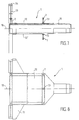
- Figure 1 is a side view of the assembly of a winder according to the invention, with partial removal of the mandrels.
- Figure 2 is a view of the rear of the winder, in section along the line II-II of Figure 1.
- Figure 3 is a top view of the winder.
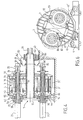
- Figure 4 is a longitudinal sectional view along line IV-IV of the Figure 2.
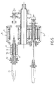
- Figure 5 is a longitudinal sectional view with partial disassembly chucks or motors.
- Figure 6 is a front view, along arrow VI of Figure 1.
- Figures 7, 8 and 9 show the rotating frame, respectively in axial section, in top view and in front view.
- Figure 10 is a detail view, in axial section, of another mode of production of a motor-mandrel assembly.
- Figure 11 is a front view of the chassis of a motor-mandrel assembly.
- FIGs 1 and 2 there is shown, respectively in side view and in rear view, the whole of a winding installation according to the invention comprising a rotating frame 1 rotatably mounted about an axis 10, normally horizontal, and bearing, in the example shown, two motor-mandrel assemblies 2, 2 'which are fixed on the rotating frame 1, symmetrically on either side of the axis of rotation 10.
- Each 2, 2 'motor-mandrel assembly includes a 3, 3' motor drive in rotation of a shaft 5, 5 ', centered on an axis 20, 20' parallel to the central axis 10 of the frame and on which is mounted a cantilever mandrel which has partially shown in Figure 1.
- the rotating frame 1 forms a mechanically welded assembly comprising a tubular shaft 11 fixed to one of its ends, on a flange 13 perpendicular to the axis 10 of the shaft 11, and two plates 12, 12 ', parallel to each other and to the axis 10, welded to the flange 13 and on the central shaft 11, respectively along two generators diametrically opposite.
- Each plate 12, 12 ' forms a platform for support of a motor-mandrel assembly 2, 2 'carrying a mandrel 21, 21' which extends cantilevered on the opposite side, passing through an opening in the flange 13.
- the frame 1 On the side of the winding, the frame 1 is supported on two separated rollers 41, 41 'rotatably mounted around horizontal axes on a fixed support 4, by through a circular support track 14 formed on the periphery of the flange 13.
- the central shaft 11 is carried by a bearing 42 mounted on a fixed base 43 formed on the foundation, and whose axis is placed at the desired level with respect to the rollers 41, 41 'so that the axis 10 of the shaft central 11 is substantially horizontal.
- a ring gear 44 on which meshes a pinion 41 'attached to one of the support rollers 41 and driven in rotation by an auxiliary motor 45 which thus controls the pivoting of the frame 1 around the axis 10 for the positioning of one or the other of the mandrels 21, 21 'in the winding position.
- the flange 13 is provided with two diametrically opposite stops 18 cooperating with a removable blocking member 46 consisting, for example, of two articulated jaws 46 mounted on the fixed support 4 and actuated by cylinders.
- the flange 13 comprises, two walls 13a, 13b welded to the plates 12, 12 ', perpendicular to the axis 10 and forming two circular segments apart, each limited inward by a straight edge 15 and outward by a circular edge 16, so as to provide two wide notches A1, A2 in the flange 13.
- the stops 18 for blocking the frame 1 are advantageously each consisting of two plates welded to the gussets 17 and extending in projection from runway 14.
- Each segment-shaped wall 13a, 13b is reinforced by ribs and the rigidity of the assembly is ensured by four gussets triangular or trapezoidal 17 each extending in the extension of a plate 12, 12 ', on either side thereof, and welded, respectively on the walls 13a, 13b.
- the tube 11, the two plates 12, 12 'and the two segments 13a, 13b thus form a rigid carcass of mechanically welded steel comprising two compartments A1, A2 with rectangular section each limited by a plate 12, 12 'and by the straight edges 15a, 15b perpendicular to the latter of the two parts and in which can integrate the two motor-mandrel assemblies 2, 2 '.
- each motor-mandrel assembly 2 comprises a rotation shaft 5 on which the cantilever is fixed mandrel 21 and which is rotated by a motor 3 placed in a chassis rigid 6 in the form of a cage comprising a cylindrical side wall 61 on which is fixed the stator 31 of the motor 3 and two flanges, respectively before 62 and rear 63.
- the rotor 32 of the motor 3 is fixed on the rotation shaft 5 which is carried by two bearings 51, 52 mounted respectively in circular orifices centered on the axis 20 of the assembly and formed respectively on the two 62, 63 of the chassis 6.
- the assembly forms a carcass strong enough to ensure the maintenance, in service, of the shaft 5 carrying the mandrel 21, the side wall 61 being itself reinforced by radiating ribs 64.
- the two front 62 and rear 63 flanges of the chassis 6 are provided, respectively, with straight sides 621, 631 placed in the same plane parallel to the axis 20, which define a flat base for the chassis 6, capable to be applied to one of the platforms 12, 12 'when the motor-mandrel assembly is placed in the corresponding compartment A1, A2, in the way shown in particular in Figures 4 and 5.
- each motor-mandrel 2 2 'assembly can be fixed removably on the corresponding platform 12, 12 'simply by four bolts for rapid assembly and disassembly.
- each motor-mandrel assembly comprising a chassis 6 bearing the motor 3, its rotation shaft 5 with these two bearings and, optionally, a mandrel 21 fixed at the end of the shaft constitutes a module for interchangeable winding which can be mounted indifferently in one or the other of the compartments A1, A2 of the central frame 1 which is perfectly symmetrical.
- the bolts 7 of chassis fixing 6 are fixed to the four angles of each platform support 12, 12 'and extend vertically so as to engage in corresponding bores 71 formed at the base of the two flanges 62, 63 of the chassis 6, symmetrically on either side of the median plane passing through the axis 20.
- the rear flange 63 is provided simply of an enlarged base so that the bolts 7 engaging in the bores 71 provided at its two ends open to the outside to allow the fitting tightening nuts 72.
- the front flange 62 shown in FIG. 11 includes two lateral sides 623 perpendicular to the lower side 621 and in which notches 65 are provided.
- the lateral sides 623, 623 ′ are spaced a little apart greater than the distance between the edges 15a, 15b of the two segments and are provided grooves 66 which engage on said segments to ensure the centering of the chassis and its attachment to the flange 13 during the installation of the chassis 6 on the platform 12.
- the heads of the bolts 7 open into the notches 65 to allow tightening of the bolts 72.
- the fixing platform 12 is provided, on the opposite side to the mandrels, a central nipple 18 placed in the median plane passing through the axis 10 and which engages in a corresponding bore in the rear flange 63 of the chassis 6 to guarantee the centering of the latter on the plate 12 in a position for which the axis 20 of the mandrel 21 and of the rotation shaft 5 is strictly parallel to the central axis 10 of the rotating frame 1 in the position of work of the motor-mandrel assembly.
- the upper side 622 of the front flange 62 opposite the base 621 has a circular profile of the same radius as the outer edges 16a, 16b of the two segments 13a, 13b, so as to reconstitute a circular flange after the installation of the frames 6, 6 'in the openings A1, A2.
- the support track 14 is therefore formed of four parts, respectively two fixed parts 14a, 14b and two mobile parts 14c, 14'c made up each of a curved profile in the shape of a circular sector and fixed respectively along the outer sides 16a, 16b of the two segments 13a, 13b and on the curved side 622 of the chassis 6 of each motor-mandrel assembly 2, 2 '.
- Said fixed and mobile parts are connected tangentially to make a continuous circular track 14 after installing and fixing the frames 6, 6 'of the two motor-mandrel assemblies 2, 2' on the platforms 12, 12 'of the frame 1.
- the ring gear 44 is divided into two fixed sectors 44a, 44b and two mobile sectors 44c, 44'c fixed respectively along the four corresponding parts of circular track 14 so as to be placed in the extension of each other to reconstitute a circular crown 44 meshing with the pinion 41 '.
- central frame 1 in welded construction which, after blocking the bolts 7, forms a compact set with chassis 6 of, 6 ', the latter simply in front be sufficiently reinforced so as to constitute a carcass, sufficiently resistant to participate in the rigidity of the whole.
- each motor-mandrel assembly forms an interchangeable module which can be dismantled as a unit and transported in workshop for maintenance.
- each motor-mandrel assembly is made in a way that allows easy disassembly of the different parts, either in the workshop or directly on the winder, as shown schematically in Figures 4 and 5 which are views in longitudinal section through an axial plane showing, the assembly of the winder and how to dismantle certain parts.
- Each mandrel 21, which may be of known type, is provided, at its base, a fixing plate 22 extended by a centering cone 23 which can engage in a corresponding conical recess 53 of the rotation shaft 5, which has a flared end so as to constitute a flange 54 on which is applied the fixing plate 22 of the mandrel, the assembly being secured, in a conventional manner, by screws.
- the shaft 5 is provided with an axial bore in which passes a rod 24 for controlling the operations of the mandrel, actuated by a control mechanism 25 fixed on the rear end of the shaft 5.
- the centering cone 23 advantageously has a fairly long reduced so that the corresponding conical space 53 of the shaft 5 extends only over a length thereof corresponding substantially to the interior of the front bearing 51 so as not to reduce the resistance of the part central of the shaft 5 carrying the rotor 32 of the motor 3.
- the front bearing 51 is housed in an orifice made in the front flange 62 whose diameter must be slightly greater than the diameter of the rotor 32 to allow passage thereof.
- the winder which has been shown in FIGS. 4 and 5 is adapted to the winding of very thin products, for example tinplate.
- the installation can be adapted to the winding of more resistant products, for example thin sheets of steel, without modifying the supporting frame 1, the mounting of each motor-mandrel assembly being simply adapted to the forces to be collected for the winding.
- the rotor 32 can be shrunk directly onto the shaft of the as shown in Figure 10.
- the bearing 51 must be removed from the front and the flange fixing of the mandrel is provided on a separate ring 55 fixed by screws on the front end of the shaft 5.
- a tube 11 to constitute the central shaft of the rotating frame 1 allows the cables to pass inside this tube electric power supply and motor control 3, 3 'as well that the hydraulic fluid passage pipes for the control expansion and constriction of the mandrels and lubrication of the bearings, which can be gathered on the rear end of the central shaft 11 and connected to means for supplying fluid by a rotating joint 27.
- the electric cables for supplying the motors 3 are connected to a manifold 35 disposed at the rear end of the shaft 11, in the axis of the hydraulic connection 26.
- the ventilation is ensured by an annular box 8 connected by ducts 81 to envelopes of the two motors, as shown in FIGS. 3, 4 and 5, the tubular central shaft 11 is used simply for the passage of the cables of electrical supply connected to the manifold 35 and of the hydraulic pipes connected to the swivel connector 26.
- the ventilation box 8 which is fixed in rotation is limited by a wall tubular lateral 82 and two flanges 83, 84 each provided with a central orifice passage of the tree 11.
- the rear flange 83 is integral with the wall 82 and associated with a seal sliding 83 'ensuring the seal with the shaft 11.
- the front flange 84 is fixed on the shaft 11 and therefore rotates with the latter. This is why it is provided, on its periphery, with an annular seal 84 ' applied against the wall 82 to ensure sealing.
- the box 8 has a ventilation circuit opening into an orifice 80 formed on the rear flange 83 or the side wall 82.
- Each branch 86 is provided with a curved outlet end 87 on which comes to apply the chassis 6 of a motor-mandrel assembly, during the installation thereof, and which opens into an orifice 88 formed in the wall tubular 61, for example between two ribs 64.
- the air introduced under pressure into the annular box 8 is thus discharged to inside the chassis 6 of the engine and escapes through the annular space 65 formed between the external wall 61 and the front flange 62 of the chassis 6.
- asynchronous motors for control of rotation of the mandrels of the electric motors allows to simplify power
- other types of motor could also be used.
- these motors could also be powered by energy hydraulic or pneumatic when power can be obtained necessary for winding.
- the rotating frame can, for example, be equipped with three platforms angularly offset by 120 °.
Landscapes
- Engineering & Computer Science (AREA)
- Mechanical Engineering (AREA)
- Manufacture Of Motors, Generators (AREA)
- Winding, Rewinding, Material Storage Devices (AREA)
- Winding Of Webs (AREA)
- Replacement Of Web Rolls (AREA)
- Compression-Type Refrigeration Machines With Reversible Cycles (AREA)
- Motor Or Generator Frames (AREA)
- Connection Of Motors, Electrical Generators, Mechanical Devices, And The Like (AREA)
- Addition Polymer Or Copolymer, Post-Treatments, Or Chemical Modifications (AREA)
- Transition And Organic Metals Composition Catalysts For Addition Polymerization (AREA)
- Polyesters Or Polycarbonates (AREA)
- Soil Working Implements (AREA)
- Spinning Or Twisting Of Yarns (AREA)
Description
Claims (20)
- Bobineuse à carrousel pour l'enroulement d'un produit en bande sur l'un ou l'autre d'au moins deux mandrins d'enroulement, comprenant un bâti tournant (1) monté rotatif sur un support fixe (4) autour d'un axe central (10), au moins deux mandrins d'enroulement (21) fixés en porte-à-faux, chacun dans le prolongement d'un arbre de rotation (5) monté rotatif sur deux paliers écartés (51,52) portés par le bâti tournant (1) et définissant un axe d'enroulement (20) du mandrin parallèle à l'axe central (10) du bâti (1) et excentré par rapport à celui-ci, et au moins deux moteurs (3) associés chacun à un mandrin (21) et comprenant chacun un rotor (32) et un stator (33) centrés sur l'axe d'enroulement (20), des moyens (44) de commande de la rotation du bâti (1) autour de son axe (10) pour la mise en place sélective de l'un ou l'autre des mandrins en position d'enroulement et des moyens (35) d'alimentation en énergie de chaque moteur (3) pour l'entraínement du mandrin (21) correspondant, caractérisée par le fait que chaque moteur (3) associé à un mandrin (21) est monté dans un châssis individuel (6) sur lequel sont montés le stator (31) du moteur (3) et les deux paliers de centrage de l'arbre de rotation (5), de façon que chaque mandrin (2), son arbre de rotation (3) et le moteur associé constituent un ensemble moto-mandrin indépendant (2) et que le bâti tournant est muni d'au moins deux organes de support, chacun, d'un tel ensemble moto-mandrin (2, 2') associés chacun à des moyens amovibles de centrage et de fixation du châssis (6), dans une position pour laquelle l'axe d'enroulement (20) défini par les paliers (51, 52) est parallèle à l'axe central (10), chaque ensemble moto-mandrin constituant ainsi un module interchangeable.
- Bobineuse selon la revendication 1, caractérisée par le fait que le châssis (6) de chaque ensemble moto-mandrin (2) comprend une base (62), (631) sensiblement plane susceptible d'être appliquée sur une plateforme correspondante (12) ménagée sur le bâti tournant (11) et constituant l'organe de support de l'ensemble moto-mandrin correspondant, ladite base (621, 631) et ladite plateforme (12) étant munies d'organes conjugués (73, 74, 7, 71) de centrage et de fixation amovible de l'une sur l'autre.
- Bobineuse selon la revendication 2, caractérisée par le fait que le bâti tournant (1) comprend un arbre central (11) monté pivotant sur le support fixe (4) autour d'un axe (40) et sur lequel sont fixées rigidement au moins deux plateformes (12, 12') placées symétriquement de part et d'autre dudit arbre central (11) et constituant chacune un l'organe de support d'un ensemble moto-mandrin (2, 2').
- Bobineuse selon l'une des revendications précédentes, caractérisée par le fait que le bâti tournant (1) comprend au moins un flasque (13) fixé à une extrémité de l'arbre central (11) perpendiculairement à celui-ci et sur lequel est ménagée une piste d'appui circulaire (14) centrée sur l'axe (10) de l'arbre (11) et roulant sur au moins deux galets écartés (41) montés rotatifs sur le support fixe (4) chacun autour d'un axe parallèle à l'axe central (10) du bâti (1).
- Bobineuse selon la revendication 4, caractérisée par le fait que l'arbre central (11) est associé à seul flasque d'appui rotatif (13) fixé sur l'une des extrémités tournée du côté des mandrins, et l'autre extrémité étant portée par un palier (42) monté sur un support fixe (43) espacé à un niveau tel que l'axe (10)de l'arbre (11) soit horizontal.
- Bobineuse selon l'une des revendications 4 et 5, caractérisée par le fait que le flasque d'appui (13) est muni d'au moins deux échancrures (A1, A2) associées chacune à un organe de support (12) et ayant chacune une largeur au moins suffisante pour le passage d'un mandrin (21) lors de la pose d'un ensemble moto-mandrin (2) sur ledit organe de support (12) et que la piste d'appui circulaire (14) comprend au moins deux secteurs fixes (14a, 14b) ménagés sur deux parties (13a, 13b) du flasque d'appui et s'étendant entre lesdites échancrures (A1, A2) et au moins deux secteurs mobiles (14c, 14'c) ménagés chacun sur le châssis (6) d'un ensemble moto-mandrin (2), lesdits secteurs fixes et mobiles ayant le même rayon de courbure de façon à reconstituer une piste circulaire continue après la pose des ensembles moto-mandrins (2, 2') sur les organes de support (12, 12')correspondants.
- Bobineuse selon la revendication 6, caractérisée par le fait que le bâti tournant (1) comprend deux plaques parallèles (12, 12') fixées de part et d'autre de l'arbre central (11) et formant chacune une plateforme de fixation d'un châssis (6) d'un ensemble moto-mandrin (2, 2'), que le flasque d'appui (13) comprend deux parties écartées (13a, 13b) en forme de segments circulaires, ayant chacune un bord extérieur circulaire (16a, 16b) sur lesquels est ménagé un secteur fixe (14a, 14b) de la piste d'appui (14) et un bord interne (15a, 15b) perpendiculaire aux deux plateformes parallèles (12, 12') et que le châssis (6) de chaque ensemble moto-mandrin (2, 2') comprend, du côté du mandrin (21), un flasque (62) limité par deux bords parallèles (623, 623') perpendiculaires à la base (621) du flasque (62) et dont l'écartement correspond, au jeu près, à la largeur de l'échancrure (A1, A2) entre les bords internes parallèles des deux segments d'appui du flasque (13), les bords parallèles (623, 623') du flasque (62) de chaque moteur (6) étant munis de rainures (66), susceptibles de s'engager par coulissement sur les bords internes correspondants (15a, 15b) des deux segments (13a, 13b) lors de la pose d'un ensemble moto-mandrin (2) sur la plateforme correspondante (12) du bâti (1).
- Bobineuse selon la revendication 7, caractérisée par le fait que chaque plateforme (12, 12') est munie d'un organe de centrage (73) coopérant avec un organe conjugué ménagé sur le flasque arrière (63) de chaque moteur (6) pour le centrage de l'ensemble moto-mandrin (2) sur la plateforme (12) dans une position pour laquelle l'axe (20) de l'arbre de rotation (15) est rigoureusement parallèle à l'axe (10) du bâti (1).
- Bobineuse selon l'une des revendications précédentes, caractérisée par le fait que chaque mandrin (21) est muni d'une plaque de fixation (22) susceptible d'être appliquée sur une bride (54, 55) ménagée à l'extrémité avant de l'arbre de rotation (5).
- Bobineuse selon la revendication 9, caractérisée par le fait que la bride (54) est constituée par une partie évasée ménagée sur l'extrémité correspondante de l'arbre de rotation (5).
- Bobineuse selon la revendication 9, caractérisée par le fait que la bride (54) est constituée d'une pièce annulaire fixée de façon amovible sur l'extrémité correspondante de l'arbre de rotation (5).
- Bobineuse selon l'une des revendications précédentes, caractérisée par le fait que chaque mandrin (21) est muni, à une extrémité de fixation sur l'arbre de rotation (5), d'une partie conique de centrage (23) susceptible de s'engager dans un évidement conique correspondant (53) de l'arbre de rotation (5) et s'étendant sur une longueur assez réduite pour que l'évidement conique (53) couvre sensiblement la même longueur que le palier correspondant (51) de l'arbre (5), des organes conjugués (26) de solidarisation en rotation étant interposés entre ladite partie de centrage (23) et l'évidement conique (53).
- Bobineuse selon l'une des revendications précédentes, caractérisée par le fait que le rotor (32) du moteur (3) est fretté sur un manchon tubulaire (33) susceptible d'être enfilé sur l'arbre de rotation (5) et muni de cannelures (34) coopérant avec des rainures correspondantes de l'arbre (5) pour la solidarisation en rotation de ce dernier avec le manchon (33) et le rotor (32).
- Bobineuse selon l'une des revendications 1 à 12, caractérisée par le fait que le rotor (32) est fretté directement sur l'arbre de rotation (5).
- Bobineuse selon l'une des revendications précédentes, caractérisée par le fait que l'arbre central (11) du bâti (1) est constitué d'un tube dans lequel sont disposés des circuits d'alimentation en énergie des moteurs (3, 3') et de commande des mandrins (21, 21').
- Bobineuse selon l'une des revendications précédentes, caractérisée par le fait que le châssis (6) du moteur (3) forme une carcasse rigide comprenant un flasque avant (62) et un flasque arrière (63) portant respectivement les deux paliers (51, 52) de l'arbre de rotation (5) et reliés par une paroi tubulaire (61) munie d'ailettes de renforcement (64) et sur laquelle est fixé le stator (31) du moteur (3).
- Bobineuse selon la revendication 16, caractérisée par le fait que le palier avant (51) de l'arbre (5) tourné du côté du mandrin (21) est logé dans un orifice ménagé dans le flasque avant (62) du châssis (6) et ayant un diamètre un peu supérieur à celui du rotor (32) pour permettre le démoulage en bloc de l'arbre 5 avec ledit rotor (32) en passant dans ledit orifice.
- Bobineuse selon la revendication 16, caractérisée par le fait qu'un espace (65) est laissé entre l'un des flasques (62) du châssis et l'extrémité correspondante de la paroi tubulaire (61), au moins sur une partie de la périphérie de celle-ci, pour permettre l'évacuation d'air de refroidissement introduit à l'intérieur dudit châssis (6) par au moins un orifice d'entrée (88) ménagé dans ladite paroi tubulaire (61) et susceptible de se brancher, à la pose du châssis (6) sur un circuit (87) porté par le bâti (1) et dans lequel est refoulé de l'air de refroidissement.
- Bobineuse selon les revendications 15 et 18, caractérisée par le fait que, à la pose du châssis (6) sur le bâti (1), l'orifice d'entrée (88) s'applique à la sur un orifice correspondant ménagé sur l'arbre central tubulaire (11) du bâti (1) et à l'intérieur duquel est refoulé l'air de refroidissement.
- Bobineuse selon la revendication 18, caractérisé par le fait que le bâti (1) est associé à un caisson annulaire (8) entourant une extrémité de l'arbre central (11) opposée au flasque d'appui (13) et comprenant une partie fixe (82, 83) munie d'un orifice (80) d'entrée d'air sous pression et une partie mobile (84) fixée sur l'arbre central (11), avec interposition de joints glissants (83', 84') entre les parties fixes et mobiles et que ladite partie mobile (84) est munie d'au moins un orifice de sortie sur lequel est branché au moins une gaine (85, 86) portée par le bâti (1) et ayant une extrémité de sortie (87) sur laquelle vient s'appliquer l'orifice d'entrée d'air (88) du châssis (6) à la pose de ce dernier sur le bâti (1).
Applications Claiming Priority (2)
| Application Number | Priority Date | Filing Date | Title |
|---|---|---|---|
| FR9607461 | 1996-06-14 | ||
| FR9607461A FR2749783B1 (fr) | 1996-06-14 | 1996-06-14 | Bobineuse a carrousel |
Publications (2)
| Publication Number | Publication Date |
|---|---|
| EP0812634A1 EP0812634A1 (fr) | 1997-12-17 |
| EP0812634B1 true EP0812634B1 (fr) | 2000-10-18 |
Family
ID=9493091
Family Applications (1)
| Application Number | Title | Priority Date | Filing Date |
|---|---|---|---|
| EP97401271A Expired - Lifetime EP0812634B1 (fr) | 1996-06-14 | 1997-06-05 | Bobineuse à carrousel |
Country Status (13)
| Country | Link |
|---|---|
| US (1) | US5904313A (fr) |
| EP (1) | EP0812634B1 (fr) |
| JP (1) | JP3902292B2 (fr) |
| KR (1) | KR100485455B1 (fr) |
| CN (1) | CN1095704C (fr) |
| AT (1) | ATE197003T1 (fr) |
| CZ (1) | CZ294652B6 (fr) |
| DE (2) | DE69703314T2 (fr) |
| ES (1) | ES2110390T3 (fr) |
| FR (1) | FR2749783B1 (fr) |
| RU (1) | RU2169690C2 (fr) |
| SK (1) | SK283914B6 (fr) |
| UA (1) | UA44747C2 (fr) |
Families Citing this family (25)
| Publication number | Priority date | Publication date | Assignee | Title |
|---|---|---|---|---|
| US6293132B1 (en) * | 1997-11-10 | 2001-09-25 | Danieli & C. Officine Meccaniche Spa | Carousel winding reel |
| EP1384533B1 (fr) * | 1997-11-27 | 2007-07-18 | Mitsubishi Heavy Industries, Ltd. | Système à enrouler une bande |
| DE19758106C2 (de) * | 1997-12-17 | 2003-09-18 | Sms Demag Ag | Karussellhaspel mit zwei Haspeldornen |
| DE10034633A1 (de) * | 2000-07-17 | 2002-01-31 | Sms Demag Ag | Vorrichtung zur Aufnahme und zum Weitertransport von, aus einer Bandwalzstraße oder einem Walzbandlager heran transportierten Walzbandbunden |
| DE10300362A1 (de) * | 2003-01-06 | 2004-07-22 | Sms Demag Ag | Verfahren und Anlage zum Walzen und anschließendem Haspeln von Metallband, insbesondere von Stahlband |
| CN103211681B (zh) * | 2009-12-21 | 2015-04-15 | 财团法人纺织产业综合研究所 | 海藻酸盐创伤敷材、其制作方法及其制作装置 |
| IT1397452B1 (it) * | 2009-12-30 | 2013-01-10 | Danieli E C Ohg S P A | Dispositivo e procedimento per avvolgere/svolgere un prodotto metallico in una linea di laminazione |
| CN102513402A (zh) * | 2011-11-29 | 2012-06-27 | 张谷旭 | 高速立式连续收线机 |
| US9067250B2 (en) * | 2012-12-20 | 2015-06-30 | Solar Turbines Incorporated | Portable tube coiler |
| CN103191935B (zh) * | 2013-03-29 | 2014-09-17 | 安阳市合力高速冷轧有限公司 | 冷轧线材倒钢装置 |
| CN104001823B (zh) * | 2014-05-05 | 2016-01-20 | 营口长胜彩板结构有限责任公司 | 液压自动放料架 |
| DE102014216221A1 (de) * | 2014-05-26 | 2015-11-26 | Sms Group Gmbh | Vorrichtung und Verfahren zum Wickeln eines Bandmaterials |
| JP6908585B2 (ja) * | 2015-07-13 | 2021-07-28 | ブルックス オートメーション インコーポレイテッド | 基板搬送装置 |
| SE539421C2 (sv) * | 2015-10-15 | 2017-09-19 | Morgårdshammar Ab | A coiling system and a method for forming a hot rolled product into an annular coil |
| NL2018889B1 (en) * | 2017-05-10 | 2018-11-15 | Vmi Holland Bv | Wind-up system and method for winding-up a strip |
| CN107161748B (zh) * | 2017-06-09 | 2019-03-12 | 浙江汇锋薄膜科技有限公司 | 一种导电薄膜的制备设备上的驱动结构 |
| CN107738954A (zh) * | 2017-11-29 | 2018-02-27 | 湖北凯乐科技股份有限公司 | 一种塑料管盘管机 |
| CN107902463A (zh) * | 2017-12-22 | 2018-04-13 | 泗洪伟创光电有限公司 | 旋转式自动放带系统 |
| CN108820998A (zh) * | 2018-08-09 | 2018-11-16 | 扬州市源联化纤有限公司 | 一种化学纤维卷绕机的交替卷绕装置 |
| EP3932585A1 (fr) * | 2020-07-03 | 2022-01-05 | Primetals Technologies Austria GmbH | Installation combinée de coulée et de laminage dotée d'un enrouleur à carrousel et procédé de fonctionnement d'une telle installation |
| DE102021101530A1 (de) * | 2021-01-25 | 2022-07-28 | Achenbach Buschhütten GmbH & Co. KG | Haspel zum Aufwickeln oder Abwickeln von bandförmigen Material und Verfahren |
| CN113753642A (zh) * | 2021-09-14 | 2021-12-07 | 江苏金韦尔机械有限公司 | 一种中间薄膜收卷机 |
| CN114406037A (zh) * | 2022-01-20 | 2022-04-29 | 江西赣电电气有限公司 | 一种硅钢片开卷机 |
| WO2023223544A1 (fr) | 2022-05-20 | 2023-11-23 | Primetals Technologies Japan株式会社 | Dispositif d'enroulement, procédé de remplacement de mandrin et mandrin |
| CN116281306B (zh) * | 2023-04-23 | 2024-07-02 | 河北德康实业有限公司 | 一种沙发布经编机收卷装置 |
Family Cites Families (6)
| Publication number | Priority date | Publication date | Assignee | Title |
|---|---|---|---|---|
| US2321646A (en) * | 1940-12-10 | 1943-06-15 | Morgan Construction Co | Apparatus for coiling wire |
| DE2041181A1 (de) * | 1970-08-19 | 1972-03-09 | Kocks Gmbh Friedrich | Vorrichtung zum Pressen und Binden von Drahtbunden |
| IT1146786B (it) * | 1981-05-20 | 1986-11-19 | Danieli Off Mecc | Perfezionamenti alle teste di macchine formatrici di spire e teste di macchina formatrici di spine cosi' perfezionate |
| DE3346219A1 (de) * | 1983-12-21 | 1985-07-18 | Mitsubishi Jukogyo K.K., Tokio/Tokyo | Vorrichtung zum antreiben mehrerer wickeltrommelwellen einer auf- oder abrollhaspel |
| JPS61124478A (ja) * | 1984-11-21 | 1986-06-12 | Mitsubishi Heavy Ind Ltd | 複胴式巻取り機または巻戻し機 |
| FR2727952A1 (fr) * | 1994-12-09 | 1996-06-14 | Clecim Sa | Bobineuse d'enroulement d'une bande |
-
1996
- 1996-06-14 FR FR9607461A patent/FR2749783B1/fr not_active Expired - Fee Related
-
1997
- 1997-06-05 DE DE69703314T patent/DE69703314T2/de not_active Expired - Lifetime
- 1997-06-05 EP EP97401271A patent/EP0812634B1/fr not_active Expired - Lifetime
- 1997-06-05 AT AT97401271T patent/ATE197003T1/de not_active IP Right Cessation
- 1997-06-05 ES ES97401271T patent/ES2110390T3/es not_active Expired - Lifetime
- 1997-06-05 DE DE0812634T patent/DE812634T1/de active Pending
- 1997-06-10 SK SK742-97A patent/SK283914B6/sk unknown
- 1997-06-11 RU RU97109362/12A patent/RU2169690C2/ru not_active IP Right Cessation
- 1997-06-11 US US08/873,273 patent/US5904313A/en not_active Expired - Lifetime
- 1997-06-12 CZ CZ19971814A patent/CZ294652B6/cs not_active IP Right Cessation
- 1997-06-13 UA UA97062811A patent/UA44747C2/uk unknown
- 1997-06-13 KR KR1019970024590A patent/KR100485455B1/ko not_active Expired - Fee Related
- 1997-06-13 CN CN97113269A patent/CN1095704C/zh not_active Expired - Fee Related
- 1997-06-16 JP JP17526397A patent/JP3902292B2/ja not_active Expired - Fee Related
Also Published As
| Publication number | Publication date |
|---|---|
| ES2110390T1 (es) | 1998-02-16 |
| JP3902292B2 (ja) | 2007-04-04 |
| ATE197003T1 (de) | 2000-11-15 |
| FR2749783B1 (fr) | 1998-09-11 |
| CZ181497A3 (cs) | 1998-03-18 |
| CZ294652B6 (cs) | 2005-02-16 |
| DE69703314D1 (de) | 2000-11-23 |
| DE69703314T2 (de) | 2001-02-22 |
| KR980000674A (ko) | 1998-03-30 |
| SK74297A3 (en) | 1998-07-08 |
| KR100485455B1 (ko) | 2005-08-11 |
| SK283914B6 (sk) | 2004-05-04 |
| CN1095704C (zh) | 2002-12-11 |
| US5904313A (en) | 1999-05-18 |
| DE812634T1 (de) | 1998-05-28 |
| FR2749783A1 (fr) | 1997-12-19 |
| UA44747C2 (uk) | 2002-03-15 |
| ES2110390T3 (es) | 2001-01-01 |
| CN1173404A (zh) | 1998-02-18 |
| JPH1072149A (ja) | 1998-03-17 |
| RU2169690C2 (ru) | 2001-06-27 |
| EP0812634A1 (fr) | 1997-12-17 |
Similar Documents
| Publication | Publication Date | Title |
|---|---|---|
| EP0812634A1 (fr) | Bobineuse à carrousel | |
| EP1241038B1 (fr) | Elément d'entraînement tel qu'une roue motrice ou un treuil de levage, comportant un moteur synchrone | |
| EP1352138B1 (fr) | Cassette laterale de transmission pour appareil roulant automoteur nettoyeur de surface immergee | |
| EP0875476A1 (fr) | Bobineuse à deux mandrins pour l'enroulement d'une bande | |
| FR2805252A1 (fr) | Dispositif de transfert de recipients comportant une roue de guidage a geometrie variable | |
| FR2774777A1 (fr) | Appareil portable de poussage et de tirage pour la pose de cable dans un conduit | |
| FR2479746A1 (fr) | Tete de roue avec reducteur incorpore pour roue motrice de vehicule | |
| FR2771319A1 (fr) | Dispositif de serrage d'un organe tubulaire notamment au moyen de mors mobiles | |
| FR2696165A1 (fr) | Dispositif pour l'enroulement en continu de bandes de matière. | |
| FR3054148A1 (fr) | Sertisseuse de boites de forme a came electronique | |
| EP0868772B1 (fr) | Systeme d'entrainement en rotation d'un dispositif | |
| EP0568750A1 (fr) | Dispositif pour enrouler ou pour enrouler dérouler du câble sur touret | |
| EP0506533B1 (fr) | Appareil de sciage | |
| FR2590337A1 (fr) | Dispositif de guidage d'un flexible au droit d'un pivot, utilisable notamment sur un robot | |
| FR2635985A1 (fr) | Dispositif pour epurer des liquides | |
| FR2859951A1 (fr) | Groupe d'entrainement pour un chariot transporteur notamment un chariot elevateur a timon | |
| EP1476321B1 (fr) | Dispositif de montage d'un pneu sur une jante de vehicule | |
| WO2013038069A1 (fr) | Dispositif de réduction du frottement entre des plaques d'étanchéité d'unités de filtration et son utilisation dans un procède de filtration | |
| EP1419100B1 (fr) | Treuil motorise | |
| FR2802890A1 (fr) | Dispositif d'entrainement de roue de bicyclette par moteurs electriques | |
| WO2026104650A1 (fr) | Mecanisme de maintien et mise en rotation d'une roue | |
| FR2610910A1 (fr) | Appareillage demontable de commande d'un mandrin de bobineuse | |
| EP0306428B1 (fr) | Mandrin de bobinage à limiteur de couple à friction | |
| FR2768420A1 (fr) | Dispositif d'enroulement de tuyau d'arrosage de jardin ou de cable autour d'un tambour | |
| FR2500573A1 (fr) | Appareil de montage et de demontage de dispositifs de raccordement de troncons cylindriques creux, par exemple de pipe-lines |
Legal Events
| Date | Code | Title | Description |
|---|---|---|---|
| PUAI | Public reference made under article 153(3) epc to a published international application that has entered the european phase |
Free format text: ORIGINAL CODE: 0009012 |
|
| AK | Designated contracting states |
Kind code of ref document: A1 Designated state(s): AT BE DE ES GB IT NL |
|
| ITCL | It: translation for ep claims filed |
Representative=s name: STUDIO TORTA SOCIETA' SEMPLICE |
|
| REG | Reference to a national code |
Ref country code: ES Ref legal event code: BA2A Ref document number: 2110390 Country of ref document: ES Kind code of ref document: T1 |
|
| TCAT | At: translation of patent claims filed | ||
| GBC | Gb: translation of claims filed (gb section 78(7)/1977) | ||
| TCNL | Nl: translation of patent claims filed | ||
| DET | De: translation of patent claims | ||
| 17P | Request for examination filed |
Effective date: 19980617 |
|
| AKX | Designation fees paid |
Free format text: AT BE DE ES GB IT NL |
|
| RBV | Designated contracting states (corrected) |
Designated state(s): AT BE DE ES GB IT NL |
|
| GRAG | Despatch of communication of intention to grant |
Free format text: ORIGINAL CODE: EPIDOS AGRA |
|
| 17Q | First examination report despatched |
Effective date: 20000203 |
|
| GRAG | Despatch of communication of intention to grant |
Free format text: ORIGINAL CODE: EPIDOS AGRA |
|
| GRAH | Despatch of communication of intention to grant a patent |
Free format text: ORIGINAL CODE: EPIDOS IGRA |
|
| GRAH | Despatch of communication of intention to grant a patent |
Free format text: ORIGINAL CODE: EPIDOS IGRA |
|
| RAP1 | Party data changed (applicant data changed or rights of an application transferred) |
Owner name: VAI CLECIM |
|
| GRAA | (expected) grant |
Free format text: ORIGINAL CODE: 0009210 |
|
| AK | Designated contracting states |
Kind code of ref document: B1 Designated state(s): AT BE DE ES GB IT NL |
|
| REF | Corresponds to: |
Ref document number: 197003 Country of ref document: AT Date of ref document: 20001115 Kind code of ref document: T |
|
| GBT | Gb: translation of ep patent filed (gb section 77(6)(a)/1977) |
Effective date: 20001018 |
|
| REF | Corresponds to: |
Ref document number: 69703314 Country of ref document: DE Date of ref document: 20001123 |
|
| REG | Reference to a national code |
Ref country code: ES Ref legal event code: FG2A Ref document number: 2110390 Country of ref document: ES Kind code of ref document: T3 |
|
| ITF | It: translation for a ep patent filed | ||
| PLBE | No opposition filed within time limit |
Free format text: ORIGINAL CODE: 0009261 |
|
| STAA | Information on the status of an ep patent application or granted ep patent |
Free format text: STATUS: NO OPPOSITION FILED WITHIN TIME LIMIT |
|
| 26N | No opposition filed | ||
| REG | Reference to a national code |
Ref country code: GB Ref legal event code: IF02 |
|
| PGFP | Annual fee paid to national office [announced via postgrant information from national office to epo] |
Ref country code: GB Payment date: 20040519 Year of fee payment: 8 |
|
| PGFP | Annual fee paid to national office [announced via postgrant information from national office to epo] |
Ref country code: NL Payment date: 20040615 Year of fee payment: 8 |
|
| PGFP | Annual fee paid to national office [announced via postgrant information from national office to epo] |
Ref country code: AT Payment date: 20040617 Year of fee payment: 8 |
|
| PG25 | Lapsed in a contracting state [announced via postgrant information from national office to epo] |
Ref country code: GB Free format text: LAPSE BECAUSE OF NON-PAYMENT OF DUE FEES Effective date: 20050605 Ref country code: AT Free format text: LAPSE BECAUSE OF NON-PAYMENT OF DUE FEES Effective date: 20050605 |
|
| PG25 | Lapsed in a contracting state [announced via postgrant information from national office to epo] |
Ref country code: NL Free format text: LAPSE BECAUSE OF NON-PAYMENT OF DUE FEES Effective date: 20060101 |
|
| GBPC | Gb: european patent ceased through non-payment of renewal fee |
Effective date: 20050605 |
|
| NLV4 | Nl: lapsed or anulled due to non-payment of the annual fee |
Effective date: 20060101 |
|
| PGFP | Annual fee paid to national office [announced via postgrant information from national office to epo] |
Ref country code: IT Payment date: 20100625 Year of fee payment: 14 |
|
| PGFP | Annual fee paid to national office [announced via postgrant information from national office to epo] |
Ref country code: ES Payment date: 20100719 Year of fee payment: 14 Ref country code: BE Payment date: 20100615 Year of fee payment: 14 |
|
| PGFP | Annual fee paid to national office [announced via postgrant information from national office to epo] |
Ref country code: DE Payment date: 20110819 Year of fee payment: 15 |
|
| BERE | Be: lapsed |
Owner name: *VAI CLECIM Effective date: 20110630 |
|
| PG25 | Lapsed in a contracting state [announced via postgrant information from national office to epo] |
Ref country code: IT Free format text: LAPSE BECAUSE OF NON-PAYMENT OF DUE FEES Effective date: 20110605 |
|
| PG25 | Lapsed in a contracting state [announced via postgrant information from national office to epo] |
Ref country code: BE Free format text: LAPSE BECAUSE OF NON-PAYMENT OF DUE FEES Effective date: 20110630 |
|
| REG | Reference to a national code |
Ref country code: DE Ref legal event code: R119 Ref document number: 69703314 Country of ref document: DE Effective date: 20130101 |
|
| PG25 | Lapsed in a contracting state [announced via postgrant information from national office to epo] |
Ref country code: DE Free format text: LAPSE BECAUSE OF NON-PAYMENT OF DUE FEES Effective date: 20130101 |
|
| REG | Reference to a national code |
Ref country code: ES Ref legal event code: FD2A Effective date: 20130605 |
|
| PG25 | Lapsed in a contracting state [announced via postgrant information from national office to epo] |
Ref country code: ES Free format text: LAPSE BECAUSE OF NON-PAYMENT OF DUE FEES Effective date: 20110606 |