EP0811759A2 - Fehlererkennungsgerät für einen Luft-Kraftstoffverhältnissensor - Google Patents
Fehlererkennungsgerät für einen Luft-Kraftstoffverhältnissensor Download PDFInfo
- Publication number
- EP0811759A2 EP0811759A2 EP97109016A EP97109016A EP0811759A2 EP 0811759 A2 EP0811759 A2 EP 0811759A2 EP 97109016 A EP97109016 A EP 97109016A EP 97109016 A EP97109016 A EP 97109016A EP 0811759 A2 EP0811759 A2 EP 0811759A2
- Authority
- EP
- European Patent Office
- Prior art keywords
- sensor
- air
- fuel ratio
- voltage
- current value
- Prior art date
- Legal status (The legal status is an assumption and is not a legal conclusion. Google has not performed a legal analysis and makes no representation as to the accuracy of the status listed.)
- Withdrawn
Links
- 239000000446 fuel Substances 0.000 title claims abstract description 123
- 230000007257 malfunction Effects 0.000 title claims abstract description 69
- 239000000203 mixture Substances 0.000 claims abstract description 30
- 238000002485 combustion reaction Methods 0.000 claims abstract description 26
- 239000007789 gas Substances 0.000 claims abstract description 18
- QVGXLLKOCUKJST-UHFFFAOYSA-N atomic oxygen Chemical compound [O] QVGXLLKOCUKJST-UHFFFAOYSA-N 0.000 claims abstract description 13
- 239000001301 oxygen Substances 0.000 claims abstract description 13
- 229910052760 oxygen Inorganic materials 0.000 claims abstract description 13
- 238000001514 detection method Methods 0.000 claims description 4
- 230000004913 activation Effects 0.000 claims 3
- 239000002826 coolant Substances 0.000 description 7
- 230000006866 deterioration Effects 0.000 description 5
- 238000000034 method Methods 0.000 description 5
- 238000002347 injection Methods 0.000 description 4
- 239000007924 injection Substances 0.000 description 4
- BASFCYQUMIYNBI-UHFFFAOYSA-N platinum Chemical compound [Pt] BASFCYQUMIYNBI-UHFFFAOYSA-N 0.000 description 4
- 230000000694 effects Effects 0.000 description 3
- 238000010276 construction Methods 0.000 description 2
- 229910052697 platinum Inorganic materials 0.000 description 2
- 230000003197 catalytic effect Effects 0.000 description 1
- 230000007423 decrease Effects 0.000 description 1
- 238000010586 diagram Methods 0.000 description 1
- 238000009792 diffusion process Methods 0.000 description 1
- 230000006870 function Effects 0.000 description 1
- 239000000126 substance Substances 0.000 description 1
- 238000011144 upstream manufacturing Methods 0.000 description 1
Images



Classifications
-
- F—MECHANICAL ENGINEERING; LIGHTING; HEATING; WEAPONS; BLASTING
- F02—COMBUSTION ENGINES; HOT-GAS OR COMBUSTION-PRODUCT ENGINE PLANTS
- F02D—CONTROLLING COMBUSTION ENGINES
- F02D41/00—Electrical control of supply of combustible mixture or its constituents
- F02D41/02—Circuit arrangements for generating control signals
- F02D41/14—Introducing closed-loop corrections
- F02D41/1438—Introducing closed-loop corrections using means for determining characteristics of the combustion gases; Sensors therefor
- F02D41/1493—Details
- F02D41/1495—Detection of abnormalities in the air/fuel ratio feedback system
Definitions
- the present invention relates to an apparatus for detecting malfunctions in air-fuel ratio sensors that detect air-fuel ratio of air-fuel mixture in internal combustion engines.
- air-fuel mixture is combusted in combustion chambers and the resulting exhaust gas is discharged to the outside through an exhaust passage.
- An air-fuel ratio sensor is located in the exhaust passage for detecting the concentration of oxygen in the exhaust gas.
- the air-fuel ratio of the air-fuel mixture is computed based on the detected oxygen concentration.
- the computed air-fuel ratio is then compared with a predetermined air-fuel ratio (usually a theoretical optimum air-fuel ratio).
- the amount of fuel in the mixture is feedback controlled such that the detected ratio becomes equal to the predetermined ratio.
- Fig. 6 is a graph showing the relationship between the value of voltage applied to such a sensor and the value of current outputted from the sensor.
- the continuous line represents the relationship between voltage and current for the predetermined air-fuel ratio.
- the alternate long and short dash line represents the relationship between voltage and current when the air-fuel ratio is rich.
- the two-dot chain line represents the relationship between voltage and current when the air-fuel ratio is lean.
- limit current value the values of current remain constant
- the limit current value is greater as the air-fuel ratio becomes leaner.
- a predetermined voltage V which is in the limit current value region, is applied to the sensor. Then, the corresponding limit current value is measured for determining the air-fuel ratio.
- the amount of fuel supplied thereto is controlled based on the air-fuel ratio detected by the air-fuel sensor. It is therefore necessary to accurately detect malfunctions such as breakage of the sensor or the sensor circuit.
- the limit current value is zero as shown in Fig. 6 when the detected air-fuel ratio matches the predetermined air-fuel ratio. Therefore, when the limit current becomes zero because of a breakage or a rupture, it is extremely difficult to judge whether the zero current is the result of a malfunction or the detected fuel ratio matching the predetermined fuel ratio.
- a malfunction detecting apparatus for an air-fuel ratio sensor (30) employed in an internal combustion engine (11) is provided.
- the engine (11) includes an intake passage (18) for introducing air-fuel mixture to a combustion chamber (17) and an exhaust passage (19) for exhausting exhaust gas generated by combustion of the air-fuel mixture in the combustion chamber (17).
- the air-fuel ratio sensor (30) is located in the exhaust passage (19). The current value of the sensor (30), when energized, varies in accordance with the applied voltage and the concentration of oxygen in the exhaust gas.
- the engine (11) also includes a controller (40) for controlling the amount of the fuel in the mixture in accordance with the magnitude of the current value when a predetermined voltage is applied to the sensor (30) such that the air-fuel ratio of the mixture becomes equal to a target air-fuel ratio.
- the sensor (30) has an applied voltage region in which the current value remains substantially zero when the air-fuel ratio of the mixture matches a predetermined theoretical air-fuel ratio.
- the malfunction detecting apparatus further includes a determiner (40), a voltage changer (44), and a malfunction detector (40). The determiner (40) determines that the amount of the fuel in the mixture is being controlled much that the air-fuel ratio matches the predetermined theoretical air-fuel ratio.
- the voltage changer (44) changes the predetermined voltage to a voltage located outside of the applied voltage region when the determiner (40) determines that the amount of fuel in the mixture is being controlled such that the air-fuel ratio matches the predetermined theoretical air-fuel ratio.
- the malfunction detector (40) detects malfunctions in the sensor (30) after the predetermined voltage is changed to the voltage located outside of the applied voltage region.
- Fig. 1 schematically shows a part of a gasoline engine 11.
- the engine 11 includes a cylinder block 12 and a cylinder head 20.
- a plurality of cylinders 13 (only one is shown) are defined in the cylinder block 12.
- a piston 14 is reciprocally housed in each cylinder 13.
- Each piston 14 is connected to a crankshaft 16 by a connecting rod 15. Reciprocation of the pistons 14 is converted into rotational motion of the crankshaft 16 by the cooperation of the connecting rods 15 and the crankshaft 16.
- a combustion chamber 17 is defined in the upper portion of each cylinder 13 by the piston 14 and the inner wall of the cylinder 13.
- An intake passage 18 and an exhaust passage 19 are connected to each combustion chamber 17.
- the cylinder block 20 is provided with a plurality of intake valves 21 and a plurality of exhaust valves 22.
- Each intake valve 21 and each exhaust valve 22 correspond to one of the cylinders 13.
- the intake valves 21 selectively communicate and disconnect the combustion chambers 17 with the intake passage 18.
- the exhaust valves 22 selectively communicate and disconnect the combustion chambers 17 with the exhaust passage 19.
- the intake passage 18 includes an air cleaner (not shown), a surge tank (not shown) and an intake manifold 25 in that order from the upstream end to the combustion chambers 17.
- the outside air is introduced to the combustion chambers 17 through these components.
- the intake manifold 25 is provided with a plurality of fuel injection valves 26, each corresponding to one of the cylinders 13. Fuel injected from the valves 26 is mixed with air flowing in the intake passage 18. The resulting air-fuel mixture is drawn into each combustion chamber 17.
- the exhaust passage 19 includes an exhaust manifold 27 and a catalytic converter (not shown) in that order from the combustion chambers 17 to the downstream end. Exhaust gas is exhausted to the outside of the engine 11 through these components.
- a cylinder block 12 is provided with a coolant temperature sensor 28 that detects the temperature THW of the engine coolant.
- a limit current type air-fuel ratio sensor (oxygen sensor) 30 is located in the exhaust passage 19. The sensor 30 detects the concentration of oxygen in the exhaust gas. The oxygen concentration in the exhaust gas corresponds to the air-fuel ratio of the air-fuel mixture drawn into the combustion chambers 17.
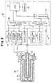
- the left side of Fig. 2 illustrates the construction of the air-fuel ratio sensor 30.
- the sensor 30 includes a double-pipe Cover 31, a cylindrical element 32 located in the cover 31 and a heater 33 located in the element 32.
- the heater 33 warms the element 32 so that it is heated more rapidly.
- a flange 31a is secured to an open end of the cover 31.
- the sensor 30 is located in the exhaust passage 19 by securing the flange 31a to the wall of the passage 19. This allows the distal end (left end as viewed in Fig. 2) of the sensor 30 to protrude from the wall of the passage 19.
- a plurality of holes 34 are formed in the cover 31 for allowing the exhaust gas in the passage 19 to flow into the cover 31.
- the element 32 is provided with an inner platinum electrode 35 and an outer platinum electrode 36 formed on the inner wall and on the outer wall, respectively.
- a resistive layer 37 is formed on the outer electrode 36 for controlling the diffusion rate of oxygen flow about the element 32.
- Exposing the resistive layer 37 to exhaust gas containing oxygen generates current between the electrodes 35 and 36.
- the value of the current is a function of the concentration of the oxygen in the exhaust gas and the value of voltage applied to the electrodes 35 and 36.
- Fig. 3 is a graph showing the relationship between the voltage applied to the electrodes 35 and 36, and the current between the electrodes 35 and 36.
- the continuous line represents a predetermined theoretical optimum air-fuel relationship.
- the alternate long and short dash line represents the relationship when the air-fuel ratio is rich.
- the two-dot chain line represents the relationship when the air-fuel ratio is lean.
- the limit applied voltage region there is a region of voltage in the graph, where the current remains constant for any air-fuel ratio, that is, optimal, rich or lean. This region is hereinafter referred to as the limit applied voltage region.
- the voltage applied to the sensor 30 is greater than the highest voltage (upper limit voltage) in the limit applied voltage region, the current value increases substantially in relation to the applied voltage.
- the voltage applied to the sensor 30 is lower than the lowest voltage (lower limit voltage) in the limit voltage region, the current value decreases substantially in relation to the applied voltage.
- the limit voltage region lies between 0.1V to 0.9V, and the limit current value is substantially 0mA.
- the upper limit voltage is 0.9 volt and the lower limit voltage is 0.1 volt.
- the limit current value increases as the air-fuel ratio increases, or the air-fuel mixture becomes leaner. In other words, the limit current value changes in accordance with the air-fuel ratio. These characteristics of the limit current are used for detecting the air-fuel ratio of the intake air.
- the engine 11 is provided with an electronic control unit (ECU) 40.
- the ECU 40 controls the fuel injection valves 26 based on detection signals from the coolant temperature sensor 28, the air-fuel ratio sensor 30 and other sensors 60.
- the ECU 40 also detects malfunctions of the air-fuel sensor 30.
- the ECU 40 includes a central processing unit (CPU) 41, a memory 42, an analog-to-digital converter 43, a current-sensing resistor 46, an input interface circuit 47 and an output interface circuit 48.
- the memory 42 previously stores a program for controlling the air-fuel ratio, a program for performing a malfunction detecting routine, and initial data.
- the CPU 41 performs various operations in accordance with the programs stored in the memory 42.
- the CPU 41 is connected to the output interface circuit 48. Also connected to the circuit 48 are the fuel injection valves 26, a voltage changer 44, a constant voltage supply 45, the heater 33 and an alarm lamp 50.
- the alarm lamp 50 is lit when a malfunction in the air-fuel ratio sensor 30 is detected, thereby notifying the driver of the malfunction.
- the CPU 41 controls the voltage changer 44 to change the voltage between the electrodes 35, 36. Specifically the CPU 41 changes the applied voltage between a first voltage Vc and a second voltage Ve.
- the first voltage Vc is applied to the electrodes 35, 36 for detecting the air-fuel ratio
- the second voltage Ve is applied for detecting malfunctions in the sensor 30.
- the first voltage Vc and the second voltage Ve have predetermined values as shown in Fig. 3.
- the first voltage Vc is set to 0.3V, which is in the limit voltage region even if the air-fuel mixture is lean or rich as seen in Fig. 3.
- the second voltage Ve is set at 1.2V, which is greater than the upper limit voltage even if the air-fuel mixture is lean or rich as seen in Fig. 3.
- the input interface circuit 47 is connected to the CPU 41 with the analog-to-digital converter 43 located in between. Also connected to the input interface circuit 47 are the current-sensing resistor 46, the coolant temperature sensor 28 and other sensors 60 for detecting the running state of the engine 11.
- the sensors 60 include a rotational speed sensor, an intake air temperature sensor and an intake air pressure sensor.
- the CPU 41 detects the current value between the electrodes 35 and 36 based on the current in the current-sensing resistor 46 and computes the air-fuel ratio of the intake air based on the detected current value between the electrodes 35 and 36.
- Fig. 4 is a flowchart of the routine.
- the CPU 41 periodically performs this routine at predetermined intervals.
- the voltage between the electrodes 35 and 36 is set to the first voltage Vc in another routine for controlling the air-fuel ratio.
- step 100 the CPU 41 reads the coolant temperature THW from the coolant temperature sensor 28.
- step 101 the CPU 41 judges whether the temperature THW is greater than a reference temperature THW 0 . If the determination condition is satisfied (THW>THW 0 ), the warm-up of the engine 11 is completed and a fuel increasing operation for the warm-up is not performed. Therefore, a sufficient length of time has elapsed since the starting of the engine. The element 32 of the sensor 30 is therefore sufficiently warmed by the heat of exhaust gas and the heter 33 and is activated. The CPU 41 thus moves to step 102.
- step 101 If the determination condition is not satisfied in step 101 (THW ⁇ THW 0 ), the CPU 41 temporarily suspends the current routine and restarts this routine after the predetermined interval.
- step 102 the CPU 41 judges whether the air-fuel ratio is being controlled to matches the predetermined theoretical optimum air-fuel ratio. For example, in a routine designed for computing the amount of fuel injection, the CPU 41 feedback controls the air-fuel ratio based on the signal from the air-fuel ratio sensor 30. If the CPU 41 is controlling the ratio to be optimal, the CPU 41 sets a determination flag to a predetermined value. The CPU 41 judges whether the flag is set to the predetermined value in step 102, thereby judging whether the air-fuel ratio is being controlled to be optimal.
- step 102 the CPU 41 temporarily suspends the current routine.
- step 102 the CPU 41 moves to step 103.
- step 103 the CPU 41 controls the voltage changer 44 for switching the voltage between the electrodes 35 and 36 in the sensor 30 from the first voltage Vc to the second voltage Ve.
- step 104 the CPU 41 computes the current value I between the electrodes 35 and 36 and then judges whether the value I is greater than a first current value Ie1 stored in the memory 42.
- the first current value Ie1 is employed for judging whether there is a malfunction such as breakage in the electrodes 35, 36 or breakage of the signal wires connecting the sensor 30 with the voltage changer 44 and with the constant voltage supply 45.
- the determination current value Ie1 may be set to 0mA. However, in this embodiment, Ie1 is set to 3mA for preventing the effect of electrical noise.
- step 104 determines that there is a malfunction in the air-fuel ratio sensor 30 and moves to step 105.
- step 105 the CPU 41 lights the alarm lamp 50, thereby notifying the passengers of the malfunction in the sensor 30.
- the CPU 41 also sets a malfunction determination flag to a state indicating that there is a malfunction in the sensor 30.
- step 104 If the determination condition is satisfied in step 104 (I>Ie), or the process of step 105 is finished, the CPU 41 temporarily suspends the current routine and restarts this routine after a predetermined interval.
- the CPU 41 judges that the air-fuel ratio of the engine 11 is being controlled to be optimal in step 120, the CPU 41 changes the voltage between the electrodes 35 and 36 from the first voltage Vc to the second voltage Ve. As a result, the voltage between the electrodes 35 and 36 becomes greater than the upper limit of the limit voltage region.
- the current I between the electrodes 35 and 36 increases to a certain current value I 0 (I 0 >Ie1).
- I 0 the current value
- the current value becomes zero, which is less than Ie1.
- the current value I has different values depending on whether the air-fuel ratio sensor 30 is normally operating or there is a malfunction in the sensor 30. This allows malfunctions in the sensor 30 to be detected by comparing the current value I with the first determination current value Ie1.
- the second voltage Ve is 1.2 V, which is positive and greater than the upper limit voltage in the limit voltage region. It is possible to employ a negative voltage (for example -0.5V), which is lower than the lower limit voltage in the limit voltage region, as the second voltage Ve.
- a negative voltage for example -0.5V
- generating a voltage that is negative with respect to a base voltage (0V) requires an inverter for lowering the base voltage to the target negative voltage. This complicates the construction of the circuit.
- the second voltage Ve has a positive value. This simplifies the circuit for detecting malfunctions in the air-fuel ratio sensor 30.
- the temperature of the element 32 In order to stabilize the current value transmitted from the sensor 30, the temperature of the element 32 must be elevated to a predetermined temperature to be activated. For example, immediately after the engine 11 is started, the temperature of the element 32 is low and the element 32 is not activated. In this state, the relationship between the applied voltage and the outputted current illustrated in Fig.3 is not obtained.
- the coolant temperature THW is compared with a reference temperature THW 0 . If THW is equal to or lower than THW 0 , detection of malfunction in the sensor 30 is not performed. Therefore, the malfunction detection is started after a certain length of time has elapsed after the engine 11 is started. At this time, the element 32 is warmed by the heat of the exhaust gas and therefore activated. This prevents the sensor 30 from wrongly detecting malfunction in the sensor 30.
- a second embodiment of the present invention will hereafter be described.
- the second embodiment is different from the first embodiment in the content of the processes of the malfunction detecting routine.
- Fig. 5 is a flowchart showing the malfunction detecting routine according to the second embodiment. In steps having the same numerals as those in Fig. 4, the CPU 41 performs the same processes as in the first embodiment.
- step 201 the CPU 41 judges whether the current value I is greater than the second determination current value Ie2 stored in the memory 42.
- the second determination current value Ie2 in the flowchart of Fig. 5 is a determination value, for determining whether the sensor 30 has deteriorated.
- the outer surface of the element 32 is exposed to exhaust gas. Substances in exhaust gas such as lead deteriorate the outer electrode 36. If the element 32 has deteriorated, the current value I becomes lower (as illustrated by a dashed line in Fig. 3) than the normal current value I illustrated by the continuous line.
- the CPU 41 determines that the sensor 30 has deteriorated when the current value I becomes equal to or lower than the second determination current value Ie2. That is, if the determination condition of step 201 is not satisfied (I ⁇ Ie2), the CPU 41 moves to step 202. In step 202, the CPU 41 blinks the alarm lamp 50, thereby notifying the driver of deterioration of the sensor 30 and sets a deterioration determination flag to a state indicating such.
- step 201 If the determination condition is satisfied in step 201 (I>Ie2), or the process of step 202 is finished, the CPU 41 temporarily suspends the current routine and restarts this routine after a predetermined interval.
- deterioration of the air-fuel ratio sensor 30 is detected by comparing the current value I in the sensor 30 with the second determination value Ie2. Therefore, the routine of Fig. 5 detects malfunctions of the sensor 30 more accurately .
- the second determination voltage Ve is positive (1.2V).
- the voltage Ve may be a negative voltage (for example, -0.5V) that is lower than the lower limit value in the limit voltage region.
- the actual air-fuel ratio of the engine 11, which is detected by the air-fuel ratio sensor 30, is feedback controlled to be equal to a target air-fuel ratio.
- the feedback control may be changed to an open-loop control. This prevents the air-fuel ratio control from being operated based on wrongly detected signal from the sensor 30.
- a malfunction detecting apparatus detects malfunctions in an air-fuel ratio sensor (30) employed in an internal combustion engine (11).
- the air-fuel ratio sensor (30) is located in an exhaust passage (19).
- the output current value of the sensor (30) varies in accordance with an applied voltage and the concentration of oxygen in the exhaust gas.
- An electronic control unit (40) controls the amount of fuel in the mixture in accordance with the magnitude of the output current of the sensor (30) such that the air-fuel ratio of the mixture is made to coincide with a target air-fuel ratio.
- the sensor (30) has an applied voltage range in which the output current value remains substantially zero when the air-fuel ratio of the mixture matches a theoretical optimum air-fuel ratio.
- a voltage changer (44) changes the applied voltage to a voltage located outside of the certian applied voltage range, and the electronic control unit (40) detects malfunctions in the sensor (30) after the applied voltage is changed by comparing the output current of the sensor with a reference value.
Landscapes
- Engineering & Computer Science (AREA)
- Chemical & Material Sciences (AREA)
- Combustion & Propulsion (AREA)
- Mechanical Engineering (AREA)
- General Engineering & Computer Science (AREA)
- Electrical Control Of Air Or Fuel Supplied To Internal-Combustion Engine (AREA)
- Combined Controls Of Internal Combustion Engines (AREA)
Applications Claiming Priority (2)
| Application Number | Priority Date | Filing Date | Title |
|---|---|---|---|
| JP14278096 | 1996-06-05 | ||
| JP142780/96 | 1996-06-05 |
Publications (2)
| Publication Number | Publication Date |
|---|---|
| EP0811759A2 true EP0811759A2 (de) | 1997-12-10 |
| EP0811759A3 EP0811759A3 (de) | 1999-05-12 |
Family
ID=15323427
Family Applications (1)
| Application Number | Title | Priority Date | Filing Date |
|---|---|---|---|
| EP97109016A Withdrawn EP0811759A3 (de) | 1996-06-05 | 1997-06-04 | Fehlererkennungsgerät für einen Luft-Kraftstoffverhältnissensor |
Country Status (2)
| Country | Link |
|---|---|
| US (1) | US5769063A (de) |
| EP (1) | EP0811759A3 (de) |
Cited By (1)
| Publication number | Priority date | Publication date | Assignee | Title |
|---|---|---|---|---|
| CN105587419A (zh) * | 2014-11-11 | 2016-05-18 | 丰田自动车株式会社 | 空燃比传感器的异常诊断装置 |
Families Citing this family (7)
| Publication number | Priority date | Publication date | Assignee | Title |
|---|---|---|---|---|
| JP3607962B2 (ja) * | 1996-08-09 | 2005-01-05 | トヨタ自動車株式会社 | 空燃比センサの劣化判定装置 |
| JP3267188B2 (ja) * | 1997-05-12 | 2002-03-18 | トヨタ自動車株式会社 | 内燃機関の触媒劣化判定装置 |
| DE19842425C2 (de) * | 1998-09-16 | 2003-10-02 | Siemens Ag | Verfahren zur Korrektur der Kennlinie einer linearen Lambda-Sonde |
| DE19947239B4 (de) * | 1999-09-30 | 2004-01-15 | Robert Bosch Gmbh | Verfahren zur Funktionsüberwachung und/oder Regenerierung einer Gassonde |
| DE102006047190B3 (de) * | 2006-10-05 | 2008-04-10 | Siemens Ag | Verfahren und Vorrichtung zum Überwachen einer Abgassonde |
| JP5737261B2 (ja) * | 2012-10-16 | 2015-06-17 | トヨタ自動車株式会社 | 車両 |
| US11193853B2 (en) * | 2019-01-28 | 2021-12-07 | Cummins Emission Solutions Inc. | Remanufacturable sensing assemblies and methods of remanufacture |
Family Cites Families (8)
| Publication number | Priority date | Publication date | Assignee | Title |
|---|---|---|---|---|
| JPH079417B2 (ja) * | 1986-03-27 | 1995-02-01 | 本田技研工業株式会社 | 酸素濃度センサの異常検出方法 |
| JPH01219328A (ja) * | 1988-02-26 | 1989-09-01 | Mitsubishi Electric Corp | 内燃機関の空燃比制御装置 |
| JPH01262460A (ja) * | 1988-04-13 | 1989-10-19 | Fujikura Ltd | 酸素センサの劣化自己診断方法 |
| US4951632A (en) * | 1988-04-25 | 1990-08-28 | Honda Giken Kogyo K.K. | Exhaust gas component concentration sensing device and method of detecting failure thereof |
| JPH07119742B2 (ja) * | 1988-06-30 | 1995-12-20 | 本田技研工業株式会社 | 酸素濃度検出装置の劣化判定方法 |
| JP2979032B2 (ja) * | 1990-12-28 | 1999-11-15 | 本田技研工業株式会社 | 排気濃度センサの劣化検出方法 |
| JPH07259612A (ja) * | 1994-03-18 | 1995-10-09 | Honda Motor Co Ltd | 内燃エンジンの排気ガス濃度センサ異常検出装置 |
| GB2301901B (en) * | 1995-06-05 | 1999-04-07 | Nippon Denso Co | Apparatus and method for diagnosing degradation or malfunction of oxygen sensor |
-
1997
- 1997-06-02 US US08/867,447 patent/US5769063A/en not_active Expired - Lifetime
- 1997-06-04 EP EP97109016A patent/EP0811759A3/de not_active Withdrawn
Cited By (3)
| Publication number | Priority date | Publication date | Assignee | Title |
|---|---|---|---|---|
| CN105587419A (zh) * | 2014-11-11 | 2016-05-18 | 丰田自动车株式会社 | 空燃比传感器的异常诊断装置 |
| EP3020949A1 (de) * | 2014-11-11 | 2016-05-18 | Toyota Jidosha Kabushiki Kaisha | Anomaliendiagnosesystem eines luft-kraftstoff-verhältnis-sensors |
| US10180112B2 (en) | 2014-11-11 | 2019-01-15 | Toyota Jidosha Kabushiki Kaisha | Abnormality diagnosis system of air-fuel ratio sensor |
Also Published As
| Publication number | Publication date |
|---|---|
| US5769063A (en) | 1998-06-23 |
| EP0811759A3 (de) | 1999-05-12 |
Similar Documents
| Publication | Publication Date | Title |
|---|---|---|
| JP3711582B2 (ja) | 酸素濃度検出装置 | |
| US5974857A (en) | Apparatus and method for controlling oxygen sensor heating | |
| US5423203A (en) | Failure determination method for O2 sensor | |
| US5454259A (en) | Failure detecting apparatus in temperature controller of air-fuel ratio sensor | |
| US6012438A (en) | System for checking a pressure sensor of a fuel supply system for an internal combustion engine | |
| US6830043B2 (en) | Secondary air supply abnormality detection system | |
| US20050072410A1 (en) | Air-fuel ratio feedback control apparatus and method for internal combustion engine | |
| WO1995023285A1 (fr) | Detecteur du type de carburant d'un moteur a combustion interne | |
| US5333446A (en) | Diagnostic system for a secondary air supplier in an engine | |
| US5970967A (en) | Method and apparatus for diagnosing an abnormality in a wide range air-fuel ratio sensor | |
| JPH10212999A (ja) | 内燃機関制御用の酸素濃度センサの学習装置及びその学習方法 | |
| KR0147916B1 (ko) | 내연 기관의 연료 성상 검출 장치 | |
| JPH11264340A (ja) | 広域空燃比センサの異常診断装置 | |
| JPH1026599A (ja) | 酸素濃度検出装置 | |
| US5769063A (en) | Malfunction detecting apparatus for air-fuel ratio sensor | |
| JP3500976B2 (ja) | ガス濃度センサの異常診断装置 | |
| US7293557B2 (en) | Abnormality detecting apparatus and abnormality detecting method for an air/fuel ratio sensor | |
| KR0122459B1 (ko) | 다기통 엔진의 공연비 제어장치 | |
| JP3988073B2 (ja) | 排出ガスセンサの異常診断装置 | |
| JP2977986B2 (ja) | 酸素センサ劣化検出方法 | |
| JPH06614Y2 (ja) | 燃料センサの異常診断装置 | |
| JPH10169501A (ja) | 空燃比センサの異常診断装置 | |
| JP2000205032A (ja) | 内燃機関の異常診断装置 | |
| JPH11132031A (ja) | 内燃機関の触媒劣化検出装置 | |
| JP4033228B2 (ja) | 酸素濃度検出装置 |
Legal Events
| Date | Code | Title | Description |
|---|---|---|---|
| PUAI | Public reference made under article 153(3) epc to a published international application that has entered the european phase |
Free format text: ORIGINAL CODE: 0009012 |
|
| 17P | Request for examination filed |
Effective date: 19970703 |
|
| AK | Designated contracting states |
Kind code of ref document: A2 Designated state(s): AT BE CH DE DK ES FI FR GB GR IE IT LI LU MC NL PT SE |
|
| PUAL | Search report despatched |
Free format text: ORIGINAL CODE: 0009013 |
|
| AK | Designated contracting states |
Kind code of ref document: A3 Designated state(s): AT BE CH DE DK ES FI FR GB GR IE IT LI LU MC NL PT SE |
|
| STAA | Information on the status of an ep patent application or granted ep patent |
Free format text: STATUS: THE APPLICATION HAS BEEN WITHDRAWN |
|
| 18W | Application withdrawn |
Withdrawal date: 19990806 |