EP0811548B1 - Dispositif de commande de changement de vitesse pour bicyclette - Google Patents
Dispositif de commande de changement de vitesse pour bicyclette Download PDFInfo
- Publication number
- EP0811548B1 EP0811548B1 EP97301277A EP97301277A EP0811548B1 EP 0811548 B1 EP0811548 B1 EP 0811548B1 EP 97301277 A EP97301277 A EP 97301277A EP 97301277 A EP97301277 A EP 97301277A EP 0811548 B1 EP0811548 B1 EP 0811548B1
- Authority
- EP
- European Patent Office
- Prior art keywords
- transmission
- gear
- control unit
- rotating body
- control member
- Prior art date
- Legal status (The legal status is an assumption and is not a legal conclusion. Google has not performed a legal analysis and makes no representation as to the accuracy of the status listed.)
- Expired - Lifetime
Links
Images


Classifications
-
- B—PERFORMING OPERATIONS; TRANSPORTING
- B62—LAND VEHICLES FOR TRAVELLING OTHERWISE THAN ON RAILS
- B62K—CYCLES; CYCLE FRAMES; CYCLE STEERING DEVICES; RIDER-OPERATED TERMINAL CONTROLS SPECIALLY ADAPTED FOR CYCLES; CYCLE AXLE SUSPENSIONS; CYCLE SIDE-CARS, FORECARS, OR THE LIKE
- B62K23/00—Rider-operated controls specially adapted for cycles, i.e. means for initiating control operations, e.g. levers, grips
- B62K23/02—Rider-operated controls specially adapted for cycles, i.e. means for initiating control operations, e.g. levers, grips hand actuated
- B62K23/06—Levers
-
- B—PERFORMING OPERATIONS; TRANSPORTING
- B62—LAND VEHICLES FOR TRAVELLING OTHERWISE THAN ON RAILS
- B62M—RIDER PROPULSION OF WHEELED VEHICLES OR SLEDGES; POWERED PROPULSION OF SLEDGES OR SINGLE-TRACK CYCLES; TRANSMISSIONS SPECIALLY ADAPTED FOR SUCH VEHICLES
- B62M25/00—Actuators for gearing speed-change mechanisms specially adapted for cycles
- B62M25/02—Actuators for gearing speed-change mechanisms specially adapted for cycles with mechanical transmitting systems, e.g. cables, levers
- B62M25/04—Actuators for gearing speed-change mechanisms specially adapted for cycles with mechanical transmitting systems, e.g. cables, levers hand actuated
-
- Y—GENERAL TAGGING OF NEW TECHNOLOGICAL DEVELOPMENTS; GENERAL TAGGING OF CROSS-SECTIONAL TECHNOLOGIES SPANNING OVER SEVERAL SECTIONS OF THE IPC; TECHNICAL SUBJECTS COVERED BY FORMER USPC CROSS-REFERENCE ART COLLECTIONS [XRACs] AND DIGESTS
- Y10—TECHNICAL SUBJECTS COVERED BY FORMER USPC
- Y10T—TECHNICAL SUBJECTS COVERED BY FORMER US CLASSIFICATION
- Y10T74/00—Machine element or mechanism
- Y10T74/15—Intermittent grip type mechanical movement
- Y10T74/1526—Oscillation or reciprocation to intermittent unidirectional motion
- Y10T74/1553—Lever actuator
- Y10T74/1555—Rotary driven element
-
- Y—GENERAL TAGGING OF NEW TECHNOLOGICAL DEVELOPMENTS; GENERAL TAGGING OF CROSS-SECTIONAL TECHNOLOGIES SPANNING OVER SEVERAL SECTIONS OF THE IPC; TECHNICAL SUBJECTS COVERED BY FORMER USPC CROSS-REFERENCE ART COLLECTIONS [XRACs] AND DIGESTS
- Y10—TECHNICAL SUBJECTS COVERED BY FORMER USPC
- Y10T—TECHNICAL SUBJECTS COVERED BY FORMER US CLASSIFICATION
- Y10T74/00—Machine element or mechanism
- Y10T74/20—Control lever and linkage systems
- Y10T74/20012—Multiple controlled elements
- Y10T74/20018—Transmission control
- Y10T74/20037—Occupant propelled vehicle
- Y10T74/20043—Transmission controlled by flexible cable
-
- Y—GENERAL TAGGING OF NEW TECHNOLOGICAL DEVELOPMENTS; GENERAL TAGGING OF CROSS-SECTIONAL TECHNOLOGIES SPANNING OVER SEVERAL SECTIONS OF THE IPC; TECHNICAL SUBJECTS COVERED BY FORMER USPC CROSS-REFERENCE ART COLLECTIONS [XRACs] AND DIGESTS
- Y10—TECHNICAL SUBJECTS COVERED BY FORMER USPC
- Y10T—TECHNICAL SUBJECTS COVERED BY FORMER US CLASSIFICATION
- Y10T74/00—Machine element or mechanism
- Y10T74/20—Control lever and linkage systems
- Y10T74/20207—Multiple controlling elements for single controlled element
- Y10T74/20256—Steering and controls assemblies
- Y10T74/20268—Reciprocating control elements
- Y10T74/2028—Handle bar type
- Y10T74/20287—Flexible control element
-
- Y—GENERAL TAGGING OF NEW TECHNOLOGICAL DEVELOPMENTS; GENERAL TAGGING OF CROSS-SECTIONAL TECHNOLOGIES SPANNING OVER SEVERAL SECTIONS OF THE IPC; TECHNICAL SUBJECTS COVERED BY FORMER USPC CROSS-REFERENCE ART COLLECTIONS [XRACs] AND DIGESTS
- Y10—TECHNICAL SUBJECTS COVERED BY FORMER USPC
- Y10T—TECHNICAL SUBJECTS COVERED BY FORMER US CLASSIFICATION
- Y10T74/00—Machine element or mechanism
- Y10T74/20—Control lever and linkage systems
- Y10T74/20396—Hand operated
- Y10T74/20402—Flexible transmitter [e.g., Bowden cable]
- Y10T74/2042—Flexible transmitter [e.g., Bowden cable] and hand operator
- Y10T74/20438—Single rotatable lever [e.g., for bicycle brake or derailleur]
Definitions
- the present invention is directed to a bicycle shifting control unit and, more particularly, to a bicycle shift control unit which communicates movement of a control lever to a cable winding member through a variable transmission.
- Japanese Utility Model 7-40390 discloses a shift control lever wherein the user may shift one gear at a time or multiple gears at a time with a single operation of the shift lever.
- the lever when shifting multiple gears at a time, the lever must swing a large distance which makes such shifting difficult while keeping a firm grasp on the handlebars. If the shift control unit is adjusted to lessen the distance the lever must travel to shift the multiple gears, then the distance the lever travels when shifting one gear at a time becomes too small for ergonomic operation.
- a lever typically can be set to conveniently shift one gear at a time or multiple gears at a time, but not both.
- a bicycle shifting control unit includes a control member operable by a user, and a rotating body for rotating in one direction to wind a shifting cable and for rotating in another direction to unwind the shifting cable.
- a first transmission transmits movement of the control member into rotation of the rotating body at a first transmission ratio
- a second transmission transmits movement of the control member into rotation of the rotating body at a second transmission ratio.
- the second transmission ratio is greater than the first transmission ratio.
- a coupling mechanism is provided for allowing the control member to be selectively coupled to the first transmission and to the second transmission.
- the first transmission comprises a first transmission gear
- the second transmission comprises a second transmission gear.
- a first slave gear is coupled to the rotating body for meshing with the first transmission gear
- a second slave gear is coupled to the rotating body for meshing with the second transmission gear.
- a control gear is disposed on an end of the control member for selectively meshing with the first transmission gear and the second transmission gear.
- a first pawl is disposed on an end of the control member for selectively transmitting motion to the first and second transmissions when the control member is moved in a first direction along a drive path
- a second pawl is disposed on an end of the control member for selectively transmitting motion to the first and second transmissions when the control member is moved in a second direction along the drive path.
- a first cam may be provided for retaining the first pawl out of contact with the first and second transmissions when the control member moves in the second direction
- a second cam may be provided for retaining the second pawl out of contact with the first and second transmissions when the control member moves in the first direction.
- the cams may be structured so that the first and second pawls are retained out of contact with the first and second transmissions when the control member is disposed at an intermediate location along the drive path.
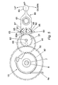
- FIG 1 is a perspective view of a particular embodiment of a bicycle shifting control unit according to the present invention.
- a brake bracket 3 which swingably supports a brake lever 2 is fixed adjacent to a grip 1a that is molded to the handlebars 1 of the bicycle, and a shifting control unit 5 for tightening and loosening an inner cable 4 a of the shifting cable 4 is attached to brake bracket 3 .
- the control body 20 of the shifting control unit 5 can be operated by the thumb and forefinger of the hand holding onto the grip 1a .
- the shifting control unit 5 comprises a fixed axle 8 that is rotatably fixed by a bolt 7 to a bracket 6 that is integrally molded with a brake bracket 3 ; a rotating body 10 that is attached to the base of this fixed axle 8 ; a position fixing mechanism 50 that fits into an indentation 11 molded in this rotating body 10 ; a first gear transmission mechanism 30 that serves as a first transmission means for transmitting the displacement of the control body 20 to the rotating body 10 to rotate it; and a second gear transmission mechanism 40 that serves as a second transmission means for transmitting the displacement of the control body 20 , at a transmission ratio greater than that of the first gear transmission mechanism 30 , i.e., by increasing the displacement of the control body 20 beyond that of the first gear transmission mechanism 30 , to the rotating body 10 to rotate it.
- control body 20 is swingably attached via a support axle 61 to a holding plate 60 fixed by a first spacer/fixture set 9a and a second spacer/fixture set 9b to a specified position of the fixed axle 8 .
- the control body 20 is composed of a fan-shaped gear 21 that is molded to one end of the control body, a knob part 23 suitably shaped for finger control that is molded to the other end of the control body, and a boss part 22 that is provided in the area between the gear 21 and the knob 23 .
- the boss part 22 is furnished with a ball joint 22a , the inner race of this ball joint 22a is fixed to the support axle 61 , and the gear 21 can swing freely in the axial direction and the peripheral direction of the support axle 61 depending on the operation of the knob 23 .
- a control displacement transmission suitable for single stage shifting is realized when the gear 21 is engaged with the drive gear 31 of the gear transmission mechanism 30
- a control displacement transmission suitable for multistage shifting is realized when the gear 21 is engaged with the drive gear 41 of the gear transmission mechanism 40 .
- the control body 20 is energized by a spring, not shown in the figures, to the position at which the gear 21 engages the drive gear 31 of the gear transmission mechanism 30 , and is ordinarily held at this single stage shifting position.
- the first gear transmission mechanism 30 that serves as the first transmission means is furnished with a drive gear 31 that is rotatably attached to a support axle 62 fixed to an auxiliary bracket 64 extending from the support plate 60 , and with a slave gear 32 that is provided to the outer periphery of the rotating body 10 so that it will engage the drive gear 31 .
- the second gear transmission mechanism 40 that serves as the second transmission means is furnished with a drive gear 41 that is rotatably attached to a support axle 63 fixed to the support plate 60 , and with a slave gear 42 that is provided to the outer periphery of the rotating body 10 so that it will engage the drive gear 41 .
- the gear ratio of the drive gear 31 and the slave gear 32 of the first gear transmission mechanism 30 is 1/3, and the gear ratio of the drive gear 41 and the slave gear 42 of the second gear transmission mechanism 40 is 1/1.
- the gear 21 of the control body is fan-shaped, but when calculated as a circular gear, the gear ratio of this gear to the drive gear 31 of the first gear transmission mechanism 30 is 3/1, and the gear ratio of this gear to the drive gear 41 of the second gear transmission mechanism 40 is 2/1.
- the rotating body 10 is furnished with a drum that is structured so that the inner wire 4a of the shifting cable 4 is wound along the cable groove 12 from the front or rear shifting unit of the bicycle (not shown in the figures).
- the rotation of the rotating body 10 in the forward or reverse rotational direction with respect to the fixed axle 8 winds or unwinds the inner cable 4a.
- the position fixing mechanism 50 comprises first and second position fixing plates 51 and 52 that are fit over the fixed axle 8 inside the rotating body 10 , and a pair of disc springs 53 fitted over the fixed axle 8 between the first position fixing plate 51 and the bottom of the indentation 11 .
- a circular through hole 51a is provided to the center of the first position fixing plate 51
- spline protrusions 51b are provided to the outer periphery of said plate.
- the fixed axle 8 is inserted through this through hole 51a , at which time the aforementioned spline protrusions 51b engage the gaps among the plurality of radial protrusions provided to the inner periphery of a cylinder 13 that forms the indentation 11 of the rotating body 10 , whereby the first position fixing plate 51 is allowed to swing around the fixed axle 8 and to rotate as one with the rotating body 10 .
- the second position fixing plate 52 engages the fixed axle 8 through a spline hole 52a , and is fixed in the upper limit position by a spacer/fixture set 9b .
- the disc springs 53 energize the first position fixing plate 51 so that it slides in the direction of the second position fixing plate 52 , creating a state in which the plurality of ridges 51c on the first position fixing plate 51 engage the plurality of grooves 52b on the position fixing plate 52 .
- the second position fixing plate 52 that is fixed to the fixed axle 8 stops the rotation of the rotating body 10 via the first position fixing plate 51 .
- the rotating body 10 is rotated with a control force greater than the specified force determined by the power of the disc springs 53 , the first position fixing plate 51 slides against the disc springs 53 in the direction in which it will detach from the second position fixing plate 52 , and the ridges 51c disengage from the grooves 52b on the second position fixing plate 52 , allowing the rotating body 10 to rotate.
- the position fixing mechanism 50 attains a state of disengagement in which a control force greater than the aforementioned set force is applied, and the rotating body 10 rotates, and when the position fixing mechanism then reattains a state of engagement, the rotating body 10 becomes fixed at another shifting position.
- this shifting control unit 5 In the case of single stage shifting, when the fingers of the hand holding onto the grip are placed on the knob 23 and the control body 20 is swung in the peripheral direction of the support axle 61 , in other words in the arrow UP direction in the second direction, the gear 21 transmits this swing displacement as the rotational displacement of the rotating body 10 via the first gear transmission mechanism 30 , i.e., via the drive gear 31 and the slave gear 32 , and this places the position fixing mechanism 50 in a state of disengagement and allows the rotating body 10 to rotate in the winding direction from the shifting position it occupied prior to the shifting operation, and this in turn results in the inner cable 4a being wound.
- the fingers of the hand holding onto the grip are placed on the knob 23 , and the control body 20 is swung in the axial direction of the support axle 61 , i.e., towards the arrow indicating multistage shifting direction in the second direction, until the gear 21 disengages from the drive gear 31 of the first gear transmission mechanism 30 and engages the drive gear 41 of the second gear transmission mechanism 40 .
- the rotating body 10 is rotated twice as much as in the case of a single stage shifting operation, even though the control body 20 swing displacement is the same, and this makes it possible for the adjacent shifting position to be skipped, and for the inner cable 4a to be wound up to the next shifting position beyond the adjacent one.
- the rotating body 10 is held at the new shifting position by the action of the position fixing mechanism 50 , as described above, allowing up-shifting to the desired shifting position to be realized.
- the control body 20 will swing, due to the force of the springs, in the first direction towards the arrow single stage shifting, and the gear 21 will return to a position at which it engages the drive gear 31 of the first gear transmission mechanism 30 .
- the control body 20 should then be swung in the second direction towards the DOWN arrow.
- FIG. 5 shows another embodiment of the shifting control unit which pertains to the present invention.
- This embodiment differs from the previous embodiment in that the gear of the control body is replaced by two ratchet pawls.
- This control body 80 comprises a first ratchet pawl 81 and a second ratchet pawl 82 that are provided facing each other at the ends of the gear transmission mechanism.
- the first ratchet pawl 81 can be swung by the support pin 85 , and the pawl tip 81 a that is molded to the tip of this pawl is energized in the clockwise direction as seen in Figure 5 by a spring 87 so that it can engage the drive gears 31 and 41 of the gear transmission mechanisms.
- the first ratchet pawl 81 is structured so that, when the control body 80 is positioned in the range of swinging in the direction of the DOWN arrow from its home position HP, the pawl tip 81a is raised by the cam member 83 so that it is detached from the drive gears 31 and 41 of the gear transmission mechanisms.
- the second ratchet pawl 82 can be swung by a support pin 86 , and a pawl tip 82a that is molded to the end of the pawl is energized in the counterclockwise direction as seen in Figure 5 by a spring 88 so that it can engage the drive gears 31 and 41 of the gear transmission mechanisms.
- the second ratchet pawl 82 is structured so that, when the control body 80 is positioned in the range of swinging in the direction of the UP arrow from its home position HP, the pawl tip 82a is raised by the cam member 84 so that it is detached from the drive gears 31 and 41 of the gear transmission mechanisms.
- This control body 80 is energized to a neutral position by a spring, not shown in the figure, so that it always returns to its home position HP which is set in the middle of its swing range in the second direction, which is the peripheral direction of the support axle 61 .
- this shifting control unit and the linkage between the control body 80 and the drive gear of the gear transmission mechanism in particular, is described as follows.
- the fingers of the hand holding onto the grip are placed on the knob 23 , and either single stage shifting or multistage shifting is selected by swinging the control body in the first direction, which is parallel to the support axle 61 of the swinging control body 80 .
- single stage shifting shall be considered to have been selected.
- the swinging control body 80 then is swung from its home position HP in the direction of the UP arrow in the second direction, and the first ratchet pawl 81 that is held up by the cam member 83 detaches from the cam member 83 and swings in the clockwise direction.
- the pawl tip 81a of the first ratchet pawl 81 then engages the drive gear 31 of the first gear transmission mechanism 30 , and the rotating body 10 rotates for unwinding the inner cable 4a . Since the linkage of the first gear transmission mechanism 30 , the rotating body 10 , and the position fixing mechanism 50 is the same as that of the previous embodiment, a repetition here of the description thereof would be redundant, and has thus been omitted.
- the control body 80 When the up-shifting operation has been completed and the cyclist's fingers have been removed from the control body 80 , the control body 80 returns to its home position HP because of its being energized to a neutral position by the spring. At this time, the control body 80 effectively swings back to its HP without applying any torque to the drive gear 31 , due to the well-known configuration of the teeth of the drive gear 31 and the pawl tip 81 a of the first ratchet pawl 81, and the pawl tip 81a is ultimately raised once again by the cam member 83 to the home position HP.
- Multistage shifting is performed by means of a similar process, although because of the difference between the first gear transmission mechanism 30 and the second gear transmission mechanism 40 , an identical control body 80 swinging displacement angle results in a rotating body 10 rotational displacement angle that is 2 times as great, and this in turn results in a greater inner cable 4a operation amount.
- control member may be constructed for swinging, rotating, or sliding.
- the transmissions may be friction types, cam types, or gear types.
Claims (13)
- Une unité de commande de changement de vitesse de bicyclette comprenant :un corps rotatif (10) destiné à effectuer une rotation dans un sens pour enrouler un câble de changement de vitesse et à effectuer une rotation dans un autre sens pour dérouler le câble de changement de vitesse ;un élément de commande (20, 80) pouvant être actionné par un utilisateur ;une première transmission (30) destinée à transmettre le déplacement de l'élément de commande (20, 80) en rotation du corps rotatif (10) à un premier braquet ;une seconde transmission (40) pour transmettre le déplacement de l'élément de commande (20, 80) en rotation du corps rotatif (10) à un second braquet ; caractérisée en ce qu'elle comprendun mécanisme d'accouplement (22, 22a, 61) destiné à permettre l'accouplement de façon sélective de l'élément de commande (20, 80) à la première transmission (30) et à la seconde transmission (40);dans laquelle le second braquet est supérieur au premier braquet.
- L'unité de commande selon la revendication 1 dans laquelle l'élément de commande (20, 80) se déplace le long d'une trajectoire de sélection pour accoupler de façon sélective l'élément de commande à la première transmission (30) et à la seconde transmission (40), dans laquelle l'élément de commande se déplace le long d'une trajectoire d'entraínement pour transmettre le déplacement de l'élément de commande (20, 80) en rotation du corps rotatif (10), et dans laquelle la trajectoire de sélection est différente de la trajectoire d'entraínement.
- L'unité de commande selon l'une ou l'autre revendication précédente dans laquelle le corps rotatif (10) est soutenu de façon à pouvoir tourner sur un axe fixe (8), et comprenant de plus un mécanisme de détermination de position (50) pour maintenir le corps rotatif (10) en des positions différentes par rapport à l'axe fixe (8), lesquelles correspondent à des positions de changement de vitesse diverses de l'unité de commande.
- L'unité de commande selon n'importe quelle revendication précédente dans laquelle le mécanisme d'accouplement (22, 22a, 61) comprend un joint à rotule (22a).
- L'unité de commande selon n'importe quelle revendication précédente dans laquelle la première transmission (30) comprend une première transmission intermédiaire (31), et dans laquelle la seconde transmission (40) comprend une seconde transmission intermédiaire (41).
- L'unité de commande selon la revendication 5 comprenant de plus un engrenage de commande (21) disposé sur une extrémité de l'élément de commande (20) destiné à s'engrener de façon sélective dans la première transmission intermédiaire (31) et la seconde transmission intermédiaire (41).
- L'unité de commande selon l'une ou l'autre des revendications 5 ou 6 comprenant de plus :un premier engrenage auxiliaire (32) accouplé au corps rotatif (10) destiné à s'engrener dans la première transmission intermédiaire (31); etun second engrenage auxiliaire (42) accouplé au corps rotatif (10) destiné à s'engrener dans la seconde transmission intermédiaire (41).
- L'unité de commande selon la revendication 7 dans laquelle le premier engrenage auxiliaire (32) est formé de façon solidaire avec le corps rotatif (10), et dans laquelle le second engrenage auxiliaire (42) est formé de façon solidaire avec le corps rotatif (10).
- L'unité de commande selon l'une ou l'autre des revendications 7 ou 8 dans laquelle un diamètre du premier engrenage auxiliaire (32) est plus grand qu'un diamètre du second engrenage auxiliaire (42).
- L'unité de commande selon la revendication 5 comprenant de plus :un premier cliquet (81) disposé sur une extrémité de l'élément de commande (80) destiné à transmettre de façon sélective le mouvement à la première transmission (30) et à la seconde transmission (40) lorsque l'élément de commande est déplacé dans un premier sens le long d'une trajectoire d'entraínement ; etun second cliquet (82) disposé sur une extrémité de l'élément de commande (80) destiné à transmettre de façon sélective le mouvement à la première transmission (30) et à la seconde transmission (40) lorsque l'élément de commande est déplacé dans un second sens le long de la trajectoire d'entraínement.
- L'unité de commande selon la revendication 10 comprenant de plus :une première came (83) destinée à maintenir le premier cliquet (81) à l'écart de la première transmission (30) et de la seconde transmission (40) lorsque l'élément de commande (80) se déplace dans le second sens ; etune seconde came (84) destinée à maintenir le second cliquet (82) à l'écart de la première transmission (30) et de la seconde transmission (40) lorsque l'élément de commande (80) se déplace dans le premier sens.
- L'unité de commande selon la revendication 11 dans laquelle le premier cliquet (81) et le second cliquet (82) sont maintenus à l'écart de la première transmission (30) et de la seconde transmission (40) lorsque l'élément de commande (10) est disposé en un emplacement intermédiaire le long de la trajectoire d'entraínement.
- L'unité de commande selon n'importe lesquelles des revendications 10 à 12 dans laquelle le premier sens est à l'opposé du second sens.
Applications Claiming Priority (2)
| Application Number | Priority Date | Filing Date | Title |
|---|---|---|---|
| US08/660,670 US5682794A (en) | 1996-06-05 | 1996-06-05 | Bicycle shifting control unit |
| US660670 | 1996-06-05 |
Publications (3)
| Publication Number | Publication Date |
|---|---|
| EP0811548A2 EP0811548A2 (fr) | 1997-12-10 |
| EP0811548A3 EP0811548A3 (fr) | 1999-01-07 |
| EP0811548B1 true EP0811548B1 (fr) | 2000-05-10 |
Family
ID=24650491
Family Applications (1)
| Application Number | Title | Priority Date | Filing Date |
|---|---|---|---|
| EP97301277A Expired - Lifetime EP0811548B1 (fr) | 1996-06-05 | 1997-02-26 | Dispositif de commande de changement de vitesse pour bicyclette |
Country Status (5)
| Country | Link |
|---|---|
| US (1) | US5682794A (fr) |
| EP (1) | EP0811548B1 (fr) |
| CN (1) | CN1073037C (fr) |
| DE (1) | DE69701922T2 (fr) |
| TW (1) | TW339317B (fr) |
Families Citing this family (35)
| Publication number | Priority date | Publication date | Assignee | Title |
|---|---|---|---|---|
| DE19703931A1 (de) * | 1997-02-04 | 1998-08-06 | Sram De Gmbh | Schalter zur Steuerung von Fahrradgetrieben |
| JP3474080B2 (ja) * | 1997-05-16 | 2003-12-08 | 株式会社シマノ | 自転車用スイッチ |
| DE19809113A1 (de) * | 1998-03-04 | 1999-09-09 | Sram De Gmbh | Schalter für Fahrradgetriebe |
| DE19915336A1 (de) * | 1999-04-03 | 2000-10-05 | Sram De Gmbh | Schalter für ein Fahrradgetriebe |
| US6244207B1 (en) * | 1999-06-02 | 2001-06-12 | Chieh-Yuan Chen | Bicycle gear shift indicating device |
| DE10002741B4 (de) * | 2000-01-22 | 2014-07-24 | Sram Deutschland Gmbh | Triggerschalter für Fahrradgetriebe |
| US6453764B1 (en) | 2000-03-03 | 2002-09-24 | Shimano, Inc. | Switch style bicycle shift control device |
| DE10055403A1 (de) * | 2000-11-09 | 2002-05-23 | Sram De Gmbh | Auslösemechanismus für getriggerte Fahrradschaltungen |
| TW532361U (en) * | 2002-08-08 | 2003-05-11 | Ad Ii Engineering Inc | Derailleur operating apparatus for bicycle |
| TWI249490B (en) * | 2003-11-18 | 2006-02-21 | Honda Motor Co Ltd | Speed value indication device for vehicle |
| US7210371B2 (en) * | 2003-12-30 | 2007-05-01 | Barnett Robert L | Control lever assembly |
| US7779718B2 (en) * | 2005-03-03 | 2010-08-24 | Sram, Llc | Bicycle shifter |
| US20060213311A1 (en) * | 2005-03-24 | 2006-09-28 | Shimano Inc. | Bicycle control device |
| JP4065290B2 (ja) * | 2005-05-23 | 2008-03-19 | 株式会社シマノ | 自転車用変速操作装置 |
| US7392723B2 (en) * | 2005-09-07 | 2008-07-01 | Shimano Inc. | Bicycle shift control mechanism |
| JP4078369B2 (ja) * | 2005-10-06 | 2008-04-23 | 株式会社シマノ | 自転車用変速操作装置 |
| EP1790564A1 (fr) * | 2005-11-24 | 2007-05-30 | Campagnolo S.r.l. | Dispositif de commande pour dérailleur de bicyclette |
| US7665383B2 (en) * | 2006-01-31 | 2010-02-23 | Shimano Inc. | Bicycle shift control device |
| US7628095B2 (en) * | 2006-05-10 | 2009-12-08 | Shimano Inc. | Bicycle shifting mechanism |
| US8065932B2 (en) * | 2007-05-16 | 2011-11-29 | Shimano Inc. | Bicycle component actuating device |
| US8161841B2 (en) * | 2007-05-16 | 2012-04-24 | Shimano Inc. | Cable operating mechanism |
| US8297146B2 (en) * | 2007-06-25 | 2012-10-30 | Shimano Inc. | Bicycle control device |
| US10017224B2 (en) * | 2008-01-08 | 2018-07-10 | Shimano Inc. | Bicycle shift operating device |
| US8640568B2 (en) * | 2009-09-04 | 2014-02-04 | Shimano Inc. | Bicycle shift control device |
| US9651138B2 (en) | 2011-09-30 | 2017-05-16 | Mtd Products Inc. | Speed control assembly for a self-propelled walk-behind lawn mower |
| US9771129B2 (en) * | 2013-06-21 | 2017-09-26 | Shimano (Singapore) Pte. Ltd. | Bicycle control device |
| US9969447B2 (en) | 2014-02-20 | 2018-05-15 | Shimano Inc. | Bicycle seatpost assembly |
| US9499224B2 (en) | 2014-02-20 | 2016-11-22 | Shimano Inc. | Bicycle seatpost assembly |
| US9604691B2 (en) * | 2014-02-20 | 2017-03-28 | Shimano Inc. | Bicycle operating device |
| US9862451B2 (en) * | 2014-09-02 | 2018-01-09 | Shimano Inc. | Bicycle control device |
| US9656717B2 (en) * | 2015-02-06 | 2017-05-23 | Shimano Inc. | Bicycle operating device |
| US10131405B2 (en) * | 2015-04-13 | 2018-11-20 | Shimano Inc. | Bicycle control device for operating a bicycle component |
| CN107010168B (zh) * | 2017-04-17 | 2022-06-21 | 珠海蓝图控制器科技有限公司 | 一种自行车换挡器 |
| US10494055B2 (en) * | 2018-03-12 | 2019-12-03 | GM Global Technology Operations LLC | Cycle shifter system with integrated sensor |
| US10780948B2 (en) * | 2018-12-10 | 2020-09-22 | Shimano Inc. | Bicycle operating device |
Family Cites Families (8)
| Publication number | Priority date | Publication date | Assignee | Title |
|---|---|---|---|---|
| DE68913113T2 (de) * | 1988-09-24 | 1994-05-26 | Shimano Kk | Gangschaltungshebel für ein Fahrrad. |
| EP0371429B1 (fr) * | 1988-11-29 | 1993-07-28 | Shimano Inc. | Dispositif de réglage de vitesse pour bicyclette |
| DE4033890A1 (de) * | 1990-10-25 | 1992-04-30 | Fichtel & Sachs Ag | Mehrgangschalter fuer uebersetzungsgetriebe an fahrraedern |
| JP3065656B2 (ja) * | 1990-11-14 | 2000-07-17 | 株式会社シマノ | 自転車用変速操作装置 |
| US5191807A (en) * | 1991-12-03 | 1993-03-09 | Hsu Yi Hsung | Indexed gear-shift mechanism |
| JP2601207Y2 (ja) * | 1992-12-28 | 1999-11-15 | 株式会社シマノ | 自転車用の変速操作装置 |
| JP2607289Y2 (ja) * | 1993-12-28 | 2001-05-28 | 株式会社シマノ | 自転車用変速操作装置 |
| JP3501509B2 (ja) * | 1994-08-23 | 2004-03-02 | 株式会社シマノ | 自転車用変速操作装置 |
-
1996
- 1996-06-05 US US08/660,670 patent/US5682794A/en not_active Expired - Lifetime
- 1996-11-02 TW TW085113376A patent/TW339317B/zh active
-
1997
- 1997-02-26 DE DE69701922T patent/DE69701922T2/de not_active Expired - Lifetime
- 1997-02-26 EP EP97301277A patent/EP0811548B1/fr not_active Expired - Lifetime
- 1997-03-19 CN CN97104521A patent/CN1073037C/zh not_active Expired - Fee Related
Also Published As
| Publication number | Publication date |
|---|---|
| EP0811548A3 (fr) | 1999-01-07 |
| US5682794A (en) | 1997-11-04 |
| CN1167062A (zh) | 1997-12-10 |
| EP0811548A2 (fr) | 1997-12-10 |
| DE69701922D1 (de) | 2000-06-15 |
| CN1073037C (zh) | 2001-10-17 |
| DE69701922T2 (de) | 2001-02-08 |
| TW339317B (en) | 1998-09-01 |
Similar Documents
| Publication | Publication Date | Title |
|---|---|---|
| EP0811548B1 (fr) | Dispositif de commande de changement de vitesse pour bicyclette | |
| EP0790175B1 (fr) | Manette de changement de vitesse pour bicyclette entourant le guidon | |
| US5775168A (en) | Combined brake and shifting device | |
| US5768945A (en) | Extension handle for a bicycle shifting device | |
| US6729203B2 (en) | Bicycle gear shifter having separate shift control members for cable pull and release | |
| EP1698550B1 (fr) | Dispositif de changement de vitesses pour bicyclette | |
| JP3592855B2 (ja) | 自転車用変速制御装置 | |
| CN100387484C (zh) | 用于自行车传动装置的自行车换档操纵装置 | |
| JP2007001572A (ja) | 自転車のディレーラ及びブレーキの統合制御デバイス | |
| EP0816217B2 (fr) | Dispositif de changement de vitesses pour une bicyclette | |
| EP0768234B1 (fr) | Dispositif de commande de changement de vitesses pour bicyclette | |
| JP3837192B2 (ja) | 自転車変速装置用制御装置 | |
| JP3065655B2 (ja) | 自転車用変速操作装置 | |
| US5564310A (en) | Shifting apparatus for a bicycle having locking members enclosed radially within a takeup element | |
| JPH0514780Y2 (fr) | ||
| JP2002274475A (ja) | 自転車用のギアチェンジ・ブレーキ一体型制御ユニット | |
| JP5937649B2 (ja) | 自転車用シフターおよびこれを備える自転車用電動システム | |
| US7421926B2 (en) | Bicycle control device with combined operation of multiple output elements | |
| JP3300024B2 (ja) | 自転車用変速操作装置 | |
| JPH0141677Y2 (fr) | ||
| JP6434578B2 (ja) | 自転車用電動システム | |
| EP0792794B1 (fr) | Dispositif uniaxial de commande pour une bicyclette |
Legal Events
| Date | Code | Title | Description |
|---|---|---|---|
| PUAI | Public reference made under article 153(3) epc to a published international application that has entered the european phase |
Free format text: ORIGINAL CODE: 0009012 |
|
| 17P | Request for examination filed |
Effective date: 19970317 |
|
| AK | Designated contracting states |
Kind code of ref document: A2 Designated state(s): DE FR IT |
|
| RIN1 | Information on inventor provided before grant (corrected) |
Inventor name: SHIBATA, TOSHIO |
|
| PUAL | Search report despatched |
Free format text: ORIGINAL CODE: 0009013 |
|
| AK | Designated contracting states |
Kind code of ref document: A3 Designated state(s): DE FR IT |
|
| GRAG | Despatch of communication of intention to grant |
Free format text: ORIGINAL CODE: EPIDOS AGRA |
|
| 17Q | First examination report despatched |
Effective date: 19990708 |
|
| GRAG | Despatch of communication of intention to grant |
Free format text: ORIGINAL CODE: EPIDOS AGRA |
|
| GRAG | Despatch of communication of intention to grant |
Free format text: ORIGINAL CODE: EPIDOS AGRA |
|
| GRAH | Despatch of communication of intention to grant a patent |
Free format text: ORIGINAL CODE: EPIDOS IGRA |
|
| GRAH | Despatch of communication of intention to grant a patent |
Free format text: ORIGINAL CODE: EPIDOS IGRA |
|
| GRAA | (expected) grant |
Free format text: ORIGINAL CODE: 0009210 |
|
| AK | Designated contracting states |
Kind code of ref document: B1 Designated state(s): DE FR IT |
|
| ITF | It: translation for a ep patent filed |
Owner name: BARZANO' E ZANARDO MILANO S.P.A. |
|
| REF | Corresponds to: |
Ref document number: 69701922 Country of ref document: DE Date of ref document: 20000615 |
|
| ET | Fr: translation filed | ||
| PLBE | No opposition filed within time limit |
Free format text: ORIGINAL CODE: 0009261 |
|
| STAA | Information on the status of an ep patent application or granted ep patent |
Free format text: STATUS: NO OPPOSITION FILED WITHIN TIME LIMIT |
|
| 26N | No opposition filed | ||
| PGFP | Annual fee paid to national office [announced via postgrant information from national office to epo] |
Ref country code: FR Payment date: 20050208 Year of fee payment: 9 |
|
| PGFP | Annual fee paid to national office [announced via postgrant information from national office to epo] |
Ref country code: IT Payment date: 20060228 Year of fee payment: 10 |
|
| REG | Reference to a national code |
Ref country code: FR Ref legal event code: ST Effective date: 20061031 |
|
| PG25 | Lapsed in a contracting state [announced via postgrant information from national office to epo] |
Ref country code: FR Free format text: LAPSE BECAUSE OF NON-PAYMENT OF DUE FEES Effective date: 20060228 |
|
| PG25 | Lapsed in a contracting state [announced via postgrant information from national office to epo] |
Ref country code: IT Free format text: LAPSE BECAUSE OF NON-PAYMENT OF DUE FEES Effective date: 20070226 |
|
| PGFP | Annual fee paid to national office [announced via postgrant information from national office to epo] |
Ref country code: DE Payment date: 20110223 Year of fee payment: 15 |
|
| REG | Reference to a national code |
Ref country code: DE Ref legal event code: R119 Ref document number: 69701922 Country of ref document: DE Effective date: 20120901 |
|
| PG25 | Lapsed in a contracting state [announced via postgrant information from national office to epo] |
Ref country code: DE Free format text: LAPSE BECAUSE OF NON-PAYMENT OF DUE FEES Effective date: 20120901 |