EP0811443A1 - Tangential rolling head - Google Patents
Tangential rolling head Download PDFInfo
- Publication number
- EP0811443A1 EP0811443A1 EP97107896A EP97107896A EP0811443A1 EP 0811443 A1 EP0811443 A1 EP 0811443A1 EP 97107896 A EP97107896 A EP 97107896A EP 97107896 A EP97107896 A EP 97107896A EP 0811443 A1 EP0811443 A1 EP 0811443A1
- Authority
- EP
- European Patent Office
- Prior art keywords
- thread
- rolling head
- roller
- rollers
- holder
- Prior art date
- Legal status (The legal status is an assumption and is not a legal conclusion. Google has not performed a legal analysis and makes no representation as to the accuracy of the status listed.)
- Granted
Links
Images


Classifications
-
- B—PERFORMING OPERATIONS; TRANSPORTING
- B21—MECHANICAL METAL-WORKING WITHOUT ESSENTIALLY REMOVING MATERIAL; PUNCHING METAL
- B21H—MAKING PARTICULAR METAL OBJECTS BY ROLLING, e.g. SCREWS, WHEELS, RINGS, BARRELS, BALLS
- B21H3/00—Making helical bodies or bodies having parts of helical shape
- B21H3/02—Making helical bodies or bodies having parts of helical shape external screw-threads ; Making dies for thread rolling
- B21H3/04—Making by means of profiled-rolls or die rolls
- B21H3/042—Thread-rolling heads
- B21H3/048—Thread-rolling heads working tangentially
Definitions
- the invention relates to a tangential rolling head according to the preamble of claim 1.
- Tangential roller heads in which thread rollers are rotatably mounted on two fork-shaped roller head arms for producing a thread, are generally known.
- the thread rolling head with the non-driven thread rollers is moved from the side onto the rotating workpiece, so that the rotational movement of the workpiece is transmitted to the thread rollers.
- the pitch of the thread to be produced results from the pitch of the thread the thread rolling.
- the thread rolls must be in a certain position to each other at the beginning of a thread rolling process and also during thread rolling. Otherwise there is no guarantee that the threads of one thread roller will engage in the threads generated on the workpiece by the other thread roller.
- the holes of the thread roller and pinion must be aligned with each other so that the axis can be inserted. This assembly requires some skill and is with one some effort. Since two installable rotational positions are possible for the rotating position of the thread roller, the fitter must ensure that the thread roller is installed in the correct rotational position.
- the invention has for its object to provide a tangential thread rolling head, in which the installation of the thread rolls is facilitated and the risk of installation in the wrong rotational position is avoided.
- the interacting claws of the thread roller and pinion designed so that the roller can only be inserted laterally in a single defined rotational position.
- this is achieved, for example, in that the ends of a pair of opposing claws on the thread roller each lie on the leg of an acute angle, the claws of the pinion being complementary in such a way that the angle formed by them diverges outwards .
- Such a design of the thread roller and pinion makes it possible, when the pinion is already installed, for the thread roller to be inserted laterally into the arm of the rolling head only in a single rotational position. Any other position would block the insertion.
- the claws are shaped at the ends with an angle so that the axes of the pinion and thread roller coincide when the claws are fully inserted laterally.
- the conical design of the ends of the claws of the pinion and thread roller not only ensure the rotational position, but also the end position. After the thread roller has been fully inserted, an alignment of the holes of the thread roller and pinion is guaranteed at the same time, so that the axis can be passed straight through without any problems.
- the roller head arms are pivotally mounted on the roller head holder about a common axis.
- an adjustment mechanism is provided to adjust the distance between the thread rolling axes according to the diameter of the thread to be formed. From the publications mentioned, for example G 81 26 319, it is known to arrange an adjusting screw in the arm of the two-armed lever of the rolling head arm facing the holder, the mutually facing ends of the adjusting screws being located opposite one another. The thread pitch can be changed by turning the two set screws. Once the change has been finally made, and to measure the distance it is known to insert a gauge between the thread rolls, the distance taken is fixed with the help of another locking screw.
- Such an adjustment mechanism has several disadvantages. One is that operation must be carried out from two different sides.
- a further embodiment of the invention provides that a single adjusting screw in one roll head arm interacts with a fixed jaw of the other roll head arm to adjust the distance between the thread rolls.
- the single screw can be arranged to save space so that the overall length of the thread rolling head can be significantly reduced compared to conventional designs.
- a further embodiment of the invention provides that the adjusting screw is arranged approximately at the level of the common axis of the roller head arms, namely obliquely to a central plane which extends between the roller head arms through the common axis of the roller head arms.
- the jaw connected to the other roller head arm extends beyond the center plane in the direction of the set screw. A particularly short rolling head is obtained in this way.
- an embodiment of the invention provides that measuring points, preferably measuring balls, are arranged on the outside of the rolling head arms for determining the center distance of the thread rolls.
- measuring points preferably measuring balls
- conventional tangential roller heads there is a separate teaching for each thread used. This increases the effort for the operator.
- a single conventional measuring instrument can be used, for example a micrometer screw or the like, in order to precisely determine the center distance of the thread rolls.
- a specific setting gauge can be omitted.
- an embodiment of the invention provides that at least one roller head arm is designed as a double-armed lever and on the arm assigned to the holder an attachment is provided which interacts with an adjustment mechanism for adjusting the attachment on the holder.
- the approach can cooperate with a nut which sits on a threaded spindle and which is guided in a rotationally fixed manner.
- the storage of the threaded spindle in the holder leads to a linear adjustment of the nut on the threaded spindle when the threaded spindle rotates and thus to a pivoting of the associated rolling head arm.
- the rolling head arms are, as is known per se, biased against one another by at least one spring, the pivoting of the one rolling head arm leads to the other arm also being pivoted. This allows the rolling head to be aligned with the center plane.
- the spindle is preferably accessible from both ends, so that the operator can choose the end that is more favorable in each case in order to achieve the center setting.
- the adjustment mechanism is mounted symmetrically on the holder.
- the rolling head can be installed rotated by 180 ° on the holder without the adjustment mechanism having to be converted.
- a scale is attached to an arm of the two-armed lever for the roller head arm, which scale interacts with a marking on the common axis.
- a further scale is attached between the holder and a rolling head arm for displaying the center position of the rolling head for the axis spacing of the thread rolls that is set in each case. Every thread size has a certain size on it Scale so that the center can be preset using the scale mentioned.
- a clamping body 10 for a thread rolling head 12 which has an L-shaped section 14, on one web of which a clamping pin 16 is attached to the outside.
- a rolling head holder 18 is attached in the rectangular recess of the L-shaped section 14. This consists of a plate-shaped part 20 and two fork arms, only one of which can be seen at 22.
- the plate-shaped section 20 is attached to the clamping body 10 by means of suitable fastening means sitting on a section of the L-shaped section 14 shown.
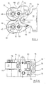
- the rolling head 12 has two fork-shaped rolling head arms 28, 30 which are designed as two-armed levers and which are rotatably supported by the arms 22 of the holder 18 about a common axis (see further figures in this regard). Threaded rollers 32, 36 are rotatably mounted between the fork arms of the arms 28, 30, specifically on an axis 38 or 40 made of hard metal. As can be seen, the right fork arm in Fig. 1 is wider than the left. This is due to the fact that a gear mechanism is arranged in the wider fork arm, a central gear wheel of the transmission, which couples both thread rollers 32, 36 to one another, is arranged on the common axis. In each case one pinion (not shown) of the transmission sits on the axis 38, 40 and interacts with the thread roller 32, 36 in a rotationally fixed manner.
- Fig. 2 shows, for example, the side view of the thread roll 32. It can be seen that two arc-segment-shaped claws 42, 44 are provided on the front side, which are opposite one another on both sides of a continuous bore 46. The arc length of the claws 42, 44 is the same, the claws are displaced relative to one another in the circumferential direction, so that a distance a is formed on one side and a distance b is formed on the other side between the ends of opposite claws 42, 44. The ends are shaped so that they lie on the legs of an angle c.
- the claws of the pinions, not shown, on the axles 38, 40 are of complementary shape.
- rollers 32, 36 By pushing the rollers 32, 36 in from the side, they can be installed in the arms 28, 30, with only a single rotational position of the thread rollers 32, 36 allowing installation.
- a position rotated by 180 ° would result, for example, in that the closer distance a would meet the closer distance of the claws of the pinions. Only with a reverse
- the claws can be brought into one another in the rotational position of the rollers.
- the claws are designed so that the bores 46 of the rollers 32, 36 are aligned with the bores of the built-in pinion when the ends of the interacting claws are properly seated, so that the axes 38, 40 after the insertion of the rollers 32, 36 without more can be inserted. It is no longer necessary to precisely align the rollers.
- Figs. 4 and 5 the tangential rolling head removed from the clamping body 10 can be seen in a side view.
- the disks 50, 52 support axles 54, 56 of the gear wheels of the transmission, which mesh with the pinions on the axles 38, 40.
- the disk 58 supports the common axis 60 about which the arms 28, 30 can be pivoted on the holder 18.
- Figs. 6 and 7 it can also be seen that the arms 28, 30 are not constructed identically, rather the roller head arm 28 is relatively short, while the other roller head arm 30 has a jaw portion 70 which extends to the short portion.
- the jaw portion 70 extends beyond the center plane that extends between the rollers 32, 36 through the common axis 60.
- an adjusting screw 72 is mounted obliquely to the center plane described in the upper roller head arm 28 in a corresponding threaded bore.
- the arms 28, 30 can be pivoted relative to one another about the common axis 60, as from the different positions in FIGS. 6 and 7.
- the distance between the rollers which are only indicated by dash-dotted lines in FIGS.
- a scale 74 is provided on the lower arm 30, which cooperates with a marking 76 on the plate 58 which is firmly connected to the axis 60 and to the arm 28, so that the marking on the scale 74 indicates the distance between the axes of the rollers 32 , 36 have each other.
- this setting is relatively rough.
- Fine adjustment is carried out with the aid of measuring balls 78, 80 on the outside of the arms 28, 30, the spacing of which can be measured using a suitable precision measuring instrument.
- a spring section 82 is also connected to the jaw section 70 and is inserted into the holding section 20 through a slot 84.
- the holding section has a bore 86 which supports a threaded spindle 88.
- the threaded spindle is acted upon on one side at 88 and also on the opposite side at 90 by a compression spring.
- the threaded spindle 88 has a threaded section 92 on which a nut-like slide 94 is seated, with which the attachment 82 cooperates.
- the slide 94 is rotatably guided through the slot 84, so that it turns when the spindle 88 is rotated in FIGS. 6 and 7 moved down and up. With the aid of this adjustment mechanism, the lower arm 30 can be pivoted in the desired manner.
- the upper arm 28 is also pivoted at the same time. This makes it possible to achieve a central position of the rolling head after, as shown for example in FIG. 7, the thread rolls 32, 36 have been given a predetermined distance from one another.
- the section 20 is covered by a plate 24 on the top, which is fastened with screws 26.
- Another plate 96 is located on the underside and is attached in the same way. Both plates 24, 96 have an opening 98, 100 for the passage of a tool for rotating the spindle 88.
- the arm 22 of the holder 18 has a scale 102 which interacts with a scale 104 on the disk 58.
- the disk 58 moves together with the arm 28, so that the center setting of the rolling head can be adjusted with the aid of the scale 102.
- Each scale line of both scales has a specific center distance between the thread rolls. If this is e.g. 36, then the lines marked 36 on both scales 102, 104 must be aligned with one another so that the center adjustment is present.
- scales corresponding to scales 74 or 102 and 104 are also provided on the opposite sides of the rolling head.
Abstract
Tangentialgewinderollkopf mit zwei gabelförmigen Rollkopfarmen (28,30), in denen mittels paralleler Achsen (38,40) Gewinderollen (32,36) drehbar gelagert sind, wobei die Gewinderollen seitlich mit einem auf den Achsen (38,40) sitzenden Ritzel eines beide Gewinderollen (32,36) koppelnden Getriebes in Eingriff stehen und Gewinderollen und Ritzel so ausgebildet sind, daß die Rollen vor dem Einbau der Achsen (38,40) seitlich einschiebbar sind, einem Rollkopfhalter (18), an dem die Rollkopfarme (28,30) um eine gemeinsame, parallel zu den Rollenachsen (38,40) verlaufende Achse (60) schwenkbar gelagert sind, Gewindemitteln zur Einstellung des Abstands der Gewinderollachsen (38,40) voneinander und Einstellmitteln für die Schwenklage des Rollkopfs zum Rollkopfhalter (18), wobei zusammenwirkende Klauen (42,44) von Gewinderolle (32,36) und Ritzel so ausgebildet sind, daß die Rolle (32,36) nur in einer einzigen definierten Drehlage seitlich eingeschoben werden kann. <IMAGE>Tangential thread rolling head with two fork-shaped rolling head arms (28, 30), in which thread rollers (32, 36) are rotatably supported by means of parallel axes (38, 40), the thread rollers with a pinion on the axes (38, 40) of one of the two thread rollers (32,36) coupling gear are engaged and threaded rollers and pinions are designed so that the rollers can be inserted laterally before the installation of the axes (38,40), a rolling head holder (18) on which the rolling head arms (28,30) are pivotally mounted about a common axis (60) running parallel to the roller axes (38, 40), threaded means for adjusting the distance between the thread rolling axes (38, 40) from one another and adjusting means for the pivoting position of the roller head relative to the roller head holder (18), interacting Claws (42, 44) of the thread roller (32, 36) and pinion are designed such that the roller (32, 36) can only be inserted laterally in a single defined rotational position. <IMAGE>
Description
Die Erfindung bezieht sich auf einen Tangentialrollkopf nach dem Oberbegriff des Anspruchs 1.The invention relates to a tangential rolling head according to the preamble of claim 1.
Tangentialrollköpfe, bei denen Gewinderollen an zwei gabelförmigen Rollkopfarmen drehbar gelagert sind zur Herstellung eines Gewindes, sind allgemein bekannt. Bei der Herstellung eines Gewindes im Wege der Kaltverformung wird der Gewinderollkopf mit den nicht angetriebenen Gewinderollen von der Seite her auf das rotierende Werkstück gefahren, so daß die Drehbewegung des Werkstücks auf die Gewinderollen übertragen wird. Die Steigung des herzustellenden Gewindes ergibt sich aus der Steigung des Gewindes der Gewinderollen. Die Gewinderollen müssen zu Beginn eines Gewinderollvorgangs und auch während des Gewinderollens in einer bestimmten Stellung zueinander stehen. Sonst ist nicht gewährleistet, daß die Gewindegänge der einen Gewinderolle in die von der anderen Gewinderolle am Werkstück erzeugten Gewindegänge eingreifen.Tangential roller heads, in which thread rollers are rotatably mounted on two fork-shaped roller head arms for producing a thread, are generally known. When producing a thread by means of cold forming, the thread rolling head with the non-driven thread rollers is moved from the side onto the rotating workpiece, so that the rotational movement of the workpiece is transmitted to the thread rollers. The pitch of the thread to be produced results from the pitch of the thread the thread rolling. The thread rolls must be in a certain position to each other at the beginning of a thread rolling process and also during thread rolling. Otherwise there is no guarantee that the threads of one thread roller will engage in the threads generated on the workpiece by the other thread roller.
Um der erwähnten Forderung Rechnung zu tragen, ist bei Tangentialrollköpfen bekanntgeworden, ein Synchrongetriebe zwischen den Gewinderollen vorzusehen. Aus Firmenschrift "Wagner Seitenrollwerkzeuge" der Gustav Wagner Maschinenfabrik ist bekanntgeworden, auf der Achse, auf der die Gewinderolle drehbar gelagert ist, auch ein Ritzel drehbar zu lagern. Das Ritzel weist an seiner Stirnfläche ein Paar von einander diametral gegenüberliegenden Klauen auf, die mit komplementären Klauen der Gewinderolle in Eingriff kommen, um eine Drehbewegung des Ritzels auf die Gewinderolle zu übertragen. Die Montage der Gewinderollen, die austauschbar sein sollen, erfolgt von der freien Seite her durch seitliches Einschieben, wobei die Klauen zueinander ausgerichtet sein müssen. Außerdem müssen die Bohrungen von Gewinderolle und Ritzel zueinander ausgerichtet sein, damit die Achse hindurchgesteckt werden kann. Diese Montage erfordert einige Geschicklichkeit und ist mit einem gewissen Aufwand verbunden. Da für die Drehposition der Gewinderolle zwei einbaufähige Drehlagen möglich sind, muß der Monteur darauf achten, daß die Gewinderolle in der richtigen Drehlage eingebaut wird.In order to take account of the requirement mentioned, it has become known in the case of tangential rolling heads to provide a synchronous gear between the threaded rollers. It has become known from the company publication "Wagner Seitenrollwerkzeuge" of the Gustav Wagner Maschinenfabrik that a pinion can also be rotatably mounted on the axis on which the thread roller is rotatably mounted. The pinion has on its end face a pair of diametrically opposed claws which engage with complementary claws of the thread roller in order to transmit a rotary movement of the pinion to the thread roller. The thread rolls, which are to be replaceable, are installed from the free side by pushing them in from the side, the claws having to be aligned with one another. In addition, the holes of the thread roller and pinion must be aligned with each other so that the axis can be inserted. This assembly requires some skill and is with one some effort. Since two installable rotational positions are possible for the rotating position of the thread roller, the fitter must ensure that the thread roller is installed in the correct rotational position.
Aus DE 29 44 499 oder auch G 81 26 219 ist bekanntgeworden, die Gewinderollen nicht über ein Getriebe zu koppeln, vielmehr frei drehbar vorzusehen, wobei jedoch Mittel vorgesehen sind, um die Gewinderollen nach dem Bearbeitungsvorgang in eine Ausgangsposition zurückzubringen. Die vorliegende Erfindung befaßt sich jedoch mit einem Tangentialrollkopf, dessen Gewinderollen über ein Getriebe gekoppelt sind.From DE 29 44 499 or G 81 26 219 it has become known that the thread rolls are not coupled via a gearbox, but rather can be rotated freely, but means are provided to return the thread rolls to an initial position after the machining operation. However, the present invention is concerned with a tangential rolling head, the thread rolls of which are coupled via a gear.
Der Erfindung liegt die Aufgabe zugrunde, einen Tangentialgewinderollkopf zu schaffen, bei dem der Einbau der Gewinderollen erleichtert und die Gefahr des Einbaus in einer falschen Drehposition vermieden wird.The invention has for its object to provide a tangential thread rolling head, in which the installation of the thread rolls is facilitated and the risk of installation in the wrong rotational position is avoided.
Diese Aufgabe wird durch die Merkmale des Anspruchs 1 gelöst.This object is solved by the features of claim 1.
Bei dem erfindungsgemäßen Tangentialgewinderollkopf sind die zusammenwirkenden Klauen von Gewinderolle und Ritzel so ausgebildet, daß die Rolle nur in einer einzigen definierten Drehlage seitlich eingeschoben werden kann. Dies wird nach einer Ausgestaltung der Erfindung etwa dadurch verwirklicht, daß die Enden eines Paars einander gegenüberliegender Klauen an der Gewinderolle jeweils auf dem Schenkel eines spitzen Winkels liegen, wobei die Klauen des Ritzels komplementär so ausgebildet sind, daß der von diesen gebildete Winkel nach außen divergiert. Durch eine derartige Ausbildung von Gewinderolle und Ritzel wird bei bereits eingebautem Ritzel nur bei einer einzigen Drehlage der Gewinderolle das seitliche Einschieben in den Arm des Rollkopfs möglich. Jede andere Lage würde das Einschieben blockieren.In the tangential thread rolling head according to the invention, the interacting claws of the thread roller and pinion designed so that the roller can only be inserted laterally in a single defined rotational position. According to one embodiment of the invention, this is achieved, for example, in that the ends of a pair of opposing claws on the thread roller each lie on the leg of an acute angle, the claws of the pinion being complementary in such a way that the angle formed by them diverges outwards . Such a design of the thread roller and pinion makes it possible, when the pinion is already installed, for the thread roller to be inserted laterally into the arm of the rolling head only in a single rotational position. Any other position would block the insertion.
Nach einer weiteren Ausgestaltung der Erfindung sind die Klauen an den Enden mit einem Winkel so geformt, daß die Achsen von Ritzel und Gewinderolle zusammenfallen, wenn die Klauen vollständig seitlich eingesteckt sind. Die konische Ausbildung der Enden der Klauen von Ritzel und Gewinderolle stellen nicht nur die Drehlage sicher, sondern auch die Endposition. Nach dem vollständigen Einstecken der Gewinderolle ist daher gleichzeitig eine Ausrichtung der Bohrungen von Gewinderolle und Ritzel gewährleistet, so daß sofort die Achse problemlos hindurchgeführt werden kann.According to a further embodiment of the invention, the claws are shaped at the ends with an angle so that the axes of the pinion and thread roller coincide when the claws are fully inserted laterally. The conical design of the ends of the claws of the pinion and thread roller not only ensure the rotational position, but also the end position. After the thread roller has been fully inserted, an alignment of the holes of the thread roller and pinion is guaranteed at the same time, so that the axis can be passed straight through without any problems.
Die Rollkopfarme sind um eine gemeinsame Achse schwenkbar am Rollkopfhalter gelagert. Außerdem ist ein Einstellmechanismus vorgesehen, um den Abstand der Gewinderollachsen voneinander einzustellen entsprechend dem Durchmesser des zu formenden Gewindes. Aus den genannten Druckschriften, beispielsweise G 81 26 319 ist bekannt, in dem dem Halter zugewandten Arm des zweiarmigen Hebels des Rollkopfarms jeweils eine Stellschraube anzuordnen, wobei die einander zugekehrten Enden der Stellschrauben gegeneinander liegen. Durch Verdrehen der beiden Stellschrauben läßt sich der Gewinderollabstand verändern. Ist die Änderung endgültig eingestellt, wobei zur Vermessung des Abstandes bekannt ist, eine Lehre zwischen die Gewinderollen einzufügen, erfolgt mit Hilfe einer weiteren Feststellschraube die Fixierung des eingenommenen Abstands. Ein derartiger Verstellmechanismus hat einige Nachteile. Der eine besteht darin, daß von zwei unterschiedlichen Seiten eine Betätigung vorgenommen werden muß. Bei beengten Platzverhältnissen, beispielsweise an einem Revolverkopf einer Werkzeugmaschine, kann das zu Schwierigkeiten führen. Die Lagerung der Stellschrauben benötigt Platz. Daher wird die Länge des Tangentialrollkopfs durch die Anordnung der Stellschrauben vergrößert. In CNC-Revolverdrehmaschinen findet sich häufig nur wenig Platz, da der Revolverkopf nur einen relativ kleinen Schwingkreisdurchmesser hat.The roller head arms are pivotally mounted on the roller head holder about a common axis. In addition, an adjustment mechanism is provided to adjust the distance between the thread rolling axes according to the diameter of the thread to be formed. From the publications mentioned, for example G 81 26 319, it is known to arrange an adjusting screw in the arm of the two-armed lever of the rolling head arm facing the holder, the mutually facing ends of the adjusting screws being located opposite one another. The thread pitch can be changed by turning the two set screws. Once the change has been finally made, and to measure the distance it is known to insert a gauge between the thread rolls, the distance taken is fixed with the help of another locking screw. Such an adjustment mechanism has several disadvantages. One is that operation must be carried out from two different sides. In confined spaces, for example on a turret head of a machine tool, this can lead to difficulties. The storage of the set screws requires space. The length of the tangential roller head is therefore increased by the arrangement of the set screws. There is often little space in CNC turret lathes because the turret head has a relatively small resonant circuit diameter.
Daher sieht eine weitere Ausgestaltung der Erfindung vor, daß eine einzige Einstellschraube in einem Rollkopfarm mit einer festen Backe des anderen Rollkopfarms zusammenwirkt zur Einstellung des Abstands der Gewinderollen. Die einzige Schraube kann platzsparend so angeordnet werden, daß die Gesamtlänge des Gewinderollkopfes gegenüber herkömmlichen Konstruktionen deutlich verringert werden kann. In diesem Zusammenhang sieht eine weitere Ausgestaltung der Erfindung vor, daß die Einstellschraube etwa in Höhe der gemeinsamen Achse der Rollkopfarme angeordnet ist, und zwar schräg zu einer Mittenebene, die sich zwischen den Rollkopfarmen durch die gemeinsame Achse der Rollkopfarme erstreckt. Die mit dem anderen Rollkopfarm verbundene Backe erstreckt sich über die Mittenebene hinaus in Richtung der Stellschraube. Auf diese Weise wird ein besonders kurzer Rollkopf erhalten.Therefore, a further embodiment of the invention provides that a single adjusting screw in one roll head arm interacts with a fixed jaw of the other roll head arm to adjust the distance between the thread rolls. The single screw can be arranged to save space so that the overall length of the thread rolling head can be significantly reduced compared to conventional designs. In this context, a further embodiment of the invention provides that the adjusting screw is arranged approximately at the level of the common axis of the roller head arms, namely obliquely to a central plane which extends between the roller head arms through the common axis of the roller head arms. The jaw connected to the other roller head arm extends beyond the center plane in the direction of the set screw. A particularly short rolling head is obtained in this way.
Wie erwähnt, erfordert die genaue Einstellung des Achsabstands der Gewinderollen eine präzise Vermessung. In diesem Zusammenhang sieht eine Ausgestaltung der Erfindung vor, daß an der Außenseite der Rollkopfarme Meßpunkte, vorzugsweise Meßkugeln, angeordnet sind zur Bestimmung des Achsabstands der Gewinderollen. Bei herkömmlichen Tangentialrollköpfen wird für jedes Gewinde eine eigene Lehre eingesetzt. Dies erhöht den Aufwand für den Betreiber. Durch die erfindungsgemäße Lösung kann ein einziges herkömmliches Meßinstrument verwendet werden, beispielsweise eine Mikrometerschraube oder dergleichen, um den Achsabstand der Gewinderollen präzise zu bestimmen. Eine spezifische Einstellehre kann entfallen.As mentioned, the precise setting of the center distance of the thread rolls requires a precise measurement. In this context, an embodiment of the invention provides that measuring points, preferably measuring balls, are arranged on the outside of the rolling head arms for determining the center distance of the thread rolls. With conventional tangential roller heads, there is a separate teaching for each thread used. This increases the effort for the operator. By means of the solution according to the invention, a single conventional measuring instrument can be used, for example a micrometer screw or the like, in order to precisely determine the center distance of the thread rolls. A specific setting gauge can be omitted.
Bei dem Formen eines Gewindes treten erhebliche Kräfte auf, die zur Durchbiegung der Achse der Gewinderollen führen können, womit ein Bruch des Ritzels verbunden sein kann. Es ist daher bei bekannten Tangentialrollköpfen auch vorgesehen, die Stahlachsen exzentrisch zu formen, um eine Durchbiegung zu kompensieren. Eine Ausgestaltung der Erfindung sieht in diesem Zusammenhang vor, daß die Achsen für die Gewinderollen aus Hartmetall geformt sind. Hartmetall reduziert die Durchbiegung drastisch und verhindert somit einen Ritzelbruch. Außerdem sind die Laufeigenschaften von Gewinderolle und Achse verbessert.When a thread is formed, considerable forces occur which can lead to the deflection of the axis of the thread rolls, which can be associated with breakage of the pinion. It is therefore also provided in known tangential rolling heads to shape the steel axes eccentrically in order to compensate for deflection. An embodiment of the invention provides in this connection that the axes for the thread rolls are formed from hard metal. Tungsten carbide drastically reduces deflection and thus prevents pinion breakage. In addition, the running properties of the thread roll and axle are improved.
Erfolgt eine Verstellung des Achsabstands der Gewinderollen in der oben beschriebenen Art und Weise für die Einstellung auf ein anderes Gewinde, ergibt sich eine unterschiedliche Lage der Gewinderollen zur durch die gemeinsame Achse der Rollkopfarme gehenden Mittenebene. Es ist daher erforderlich, nach der Einstellung des Achsabstands die Mittigkeit wieder herzustellen. In diesem Zusammenhang sieht eine Ausgestaltung der Erfindung vor, daß mindestens ein Rollkopfarm als doppelarmiger Hebel ausgeführt ist und an dem dem Halter zugeordneten Arm ein Ansatz vorgesehen ist, der mit einem Verstellmechanismus zur Verstellung des Ansatzes am Halter zusammenwirkt. Zur Verwirklichung des Gedankens kann nach einer weiteren Ausgestaltung der Erfindung der Ansatz mit einer Mutter zusammenwirken, die auf einer Gewindespindel sitzt und die drehfest geführt ist. Die Lagerung der Gewindespindel im Halter führt bei einer Drehung der Gewindespindel zu einer Linearverstellung der Mutter auf der Gewindespindel und damit zu einem Verschwenken des zugeordneten Rollkopfarmes. Da die Rollkopfarme, wie an sich bekannt, über mindestens eine Feder gegeneinander vorgespannt sind, führt die Verschwenkung des einen Rollkopfarms zum Mitverschwenken des anderen Arms. Dadurch kann der Rollkopf im Hinblick auf die Mittenebene ausgerichtet werden. Die Spindel ist nach einer weiteren Ausgestaltung der Erfindung vorzugsweise von beiden Enden zugänglich, so daß sich die Bedienungsperson das jeweils günstigere Ende aussuchen kann, um die Mitteneinstellung zu bewerkstelligen.If the center distance of the thread rolls is adjusted in the manner described above for the adjustment to a different thread, the thread rolls are positioned differently from the center plane passing through the common axis of the rolling head arms. It is It is therefore necessary to restore the center after the center distance has been set. In this context, an embodiment of the invention provides that at least one roller head arm is designed as a double-armed lever and on the arm assigned to the holder an attachment is provided which interacts with an adjustment mechanism for adjusting the attachment on the holder. To realize the idea, according to a further embodiment of the invention, the approach can cooperate with a nut which sits on a threaded spindle and which is guided in a rotationally fixed manner. The storage of the threaded spindle in the holder leads to a linear adjustment of the nut on the threaded spindle when the threaded spindle rotates and thus to a pivoting of the associated rolling head arm. Since the rolling head arms are, as is known per se, biased against one another by at least one spring, the pivoting of the one rolling head arm leads to the other arm also being pivoted. This allows the rolling head to be aligned with the center plane. According to a further embodiment of the invention, the spindle is preferably accessible from both ends, so that the operator can choose the end that is more favorable in each case in order to achieve the center setting.
Stöße bei einem Schalten des Revolverkopfes von Werkzeugmaschinen können zu einem Bruch des Ansatzes oder auch der Spindel führen. Um dieser Gefahr zu begegnen, ist nach einer weiteren Ausgestaltung der Erfindung vorgesehen, daß die Spindel an entgegengesetzten Enden mit einer Druckfeder beaufschlagt ist.Shocks when switching the turret of machine tools can lead to breakage of the attachment or the spindle. In order to counter this danger, it is provided according to a further embodiment of the invention that the spindle is acted upon by a compression spring at opposite ends.
Nach einer weiteren Ausgestaltung der Erfindung ist vorgesehen, daß der Verstellmechanismus symmetrisch am Halter angebracht ist. Hierdurch kann der Rollkopf am Halter um 180° verdreht eingebaut werden, ohne daß der Verstellmechanismus umgebaut werden muß.According to a further embodiment of the invention, it is provided that the adjustment mechanism is mounted symmetrically on the holder. As a result, the rolling head can be installed rotated by 180 ° on the holder without the adjustment mechanism having to be converted.
Nach einer weiteren Ausgestaltung der Erfindung ist vorgesehen, daß an einem Arm des zweiarmigen Hebels für den Rollkopfarm eine Skala angebracht ist, die mit einer Markierung an der gemeinsamen Achse zusammenwirkt. Mit Hilfe einer derartigen Skala kann der Achsabstand der Gewinderollen grob eingestellt werden.According to a further embodiment of the invention, it is provided that a scale is attached to an arm of the two-armed lever for the roller head arm, which scale interacts with a marking on the common axis. With the help of such a scale, the center distance of the thread rolls can be roughly adjusted.
Nach einer weiteren Ausgestaltung der Erfindung ist zwischen Halter und einem Rollkopfarm eine weitere Skala angebracht zur Anzeige der Mittenlage des Rollkopfes für den jeweils eingestellten Achsabstand der Gewinderollen. Zu jeder Gewindegröße gehört eine bestimmte Größe auf der Skala, so daß die Mittigkeit mit Hilfe der erwähnten Skala voreingestellt werden kann.According to a further embodiment of the invention, a further scale is attached between the holder and a rolling head arm for displaying the center position of the rolling head for the axis spacing of the thread rolls that is set in each case. Every thread size has a certain size on it Scale so that the center can be preset using the scale mentioned.
Die Erfindung wird nachfolgend anhand von Zeichnungen näher erläutert.
- Fig. 1
- zeigt perspektivisch einen Tangentialgewinderollkopf nach der Erfindung.
- Fig. 2
- zeigt eine Seitenansicht einer Gewinderolle des Rollkopfs nach Fig. 1.
- Fig. 3
- zeigt einen Schnitt durch die Darstellung nach Fig. 2 entlang der Linie 3-3.
- Fig. 4
- zeigt die Seitenansicht des Gewinderollkopfs nach Fig. 1 ohne Aufspannkörper.
- Fig. 5
- zeigt die Draufsicht auf die Darstellung nach Fig. 4 entlang dem Richtungspfeil 5.
- Fig. 6
- zeigt eine ähnliche Darstellung wie Fig. 4, jedoch bei Weglassung eines Arms des gabelartigen Rollkopfhalters und mit Schnitt durch ein Verstellmittel für die Verschwenkung des Rollkopfs.
- Fig. 7
- zeigt eine ähnliche Darstellung wie Fig. 6, jedoch in einer anderen Schwenkposition der Rollkopfarme.
- Fig. 1
- shows in perspective a tangential thread rolling head according to the invention.
- Fig. 2
- shows a side view of a thread roll of the rolling head of FIG. 1st
- Fig. 3
- shows a section through the representation of FIG. 2 along the line 3-3.
- Fig. 4
- shows the side view of the thread rolling head of FIG. 1 without clamping body.
- Fig. 5
- shows the top view of the illustration of FIG. 4 along the direction arrow 5.
- Fig. 6
- shows a similar representation as FIG. 4, but with the omission of an arm of the fork-like rolling head holder and with a section through an adjusting means for pivoting the rolling head.
- Fig. 7
- shows a representation similar to Fig. 6, but in a different pivot position of the roller head arms.
In Fig. 1 ist ein Aufspannkörper 10 für einen Gewinderollkopf 12 dargestellt, der einen L-förmigen Abschnitt 14 aufweist, an dessen einem Steg an der Außenseite ein Einspannzapfen 16 angebracht ist. In der rechteckigen Ausnehmung des L-förmigen Abschnitts 14 ist ein Rollkopfhalter 18 angebracht. Dieser besteht aus einem plattenförmigen Teil 20 und zwei Gabelarmen, von denen nur einer bei 22 zu erkennen ist. Der plattenförmige Abschnitt 20 wird mit Hilfe geeigneter Befestigungsmittel auf einem gezeigten Absatz des L-förmigen Abschnitts 14 aufsitzend am Aufspannkörper 10 befestigt.In Fig. 1, a clamping
Der Rollkopf 12 weist zwei gabelförmige Rollkopfarme 28, 30 auf, die als zweiarmige Hebel ausgeführt sind und die von den Armen 22 des Halters 18 um eine gemeinsame Achse drehbar gelagert sind (siehe hierzu weitere Figuren). Zwischen den Gabelarmen der Arme 28, 30 sind Gewinderollen 32, 36 drehbar gelagert, und zwar auf einer Achse 38 bzw. 40 aus Hartmetall. Wie erkennbar, ist der in Fig. 1 rechte Gabelarm breiter als der linke. Dies beruht darauf, daß in dem breiteren Gabelarm ein Zahnradgetriebe angeordnet ist, wobei ein mittleres Zahnrad des Getriebes, das beide Gewinderollen 32, 36 miteinander koppelt, auf der gemeinsamen Achse angeordnet ist. Jeweils ein Ritzel (nicht gezeigt) des Getriebes sitzt auf der Achse 38, 40 und wirkt drehfest mit der Gewinderolle 32, 36 zusammen.The rolling
Fig. 2 zeigt zum Beispiel die Seitenansicht der Gewinderolle 32. Man erkennt, daß an der Stirnseite zwei bogensegmentförmige Klauen 42, 44 vorgesehen sind, die auf beiden Seiten einer durchgehenden Bohrung 46 einander gegenüberliegen. Die Bogenlänge der Klauen 42, 44 ist zwar gleich, die Klauen sind relativ zueinander in Umfangsrichtung verschoben, so daß sich auf der einen Seite ein Abstand a und auf der anderen Seite ein Abstand b zwischen den Enden gegenüberliegender Klauen 42, 44 bildet. Die Enden sind so geformt, daß sie auf den Schenkeln eines Winkels c liegen. Die Klauen der nicht gezeigten Ritzel auf den Achsen 38, 40 sind komplementär geformt. Durch seitliches Einschieben der Rollen 32, 36 können diese in den Armen 28, 30 eingebaut werden, wobei nur eine einzige Drehlage der Gewinderollen 32, 36 den Einbau ermöglicht. Eine um 180° verdrehte Lage würde dazu führen, daß zum Beispiel der engere Abstand a gegen den engeren Abstand der Klauen der Ritzel stoßen würde. Nur bei einer umgekehrten Drehposition der Rollen können die Klauen ineinandergeführt werden. Außerdem sind die Klauen so ausgebildet, daß bei einer satten Anlage der Enden der zusammenwirkenden Klauen die Bohrungen 46 der Rollen 32, 36 mit den Bohrungen der eingebauten Ritzel ausgerichtet sind, so daß die Achsen 38, 40 nach dem Einsetzen der Rollen 32, 36 ohne weiteres eingesteckt werden können. Ein genaues Ausrichten der Rollen ist hierzu nicht mehr erforderlich.Fig. 2 shows, for example, the side view of the
In Fign. 4 und 5 ist der aus dem Einspannkörper 10 ausgebaute Tangentialrollkopf in Seitenansicht zu erkennen. Die Scheiben 50, 52 lagern Achsen 54, 56 der Zahnräder des Getriebes, die mit den Ritzeln auf den Achsen 38, 40 kämmen. Die Scheibe 58 lagert die gemeinsame Achse 60, um die die Arme 28, 30 am Halter 18 schwenkbar sind. Außerdem befindet sich dahinter entweder ein einziges großes Zahnrad oder eine Anordnung von drei Zahnrädern, wobei das mittlere auf der Achse 60 sitzt. In diesem Fall findet ein Eingriff mit den Zahnrädern auf den Achsen 54, 56 statt, so daß die Drehung der Gewinderollen 32, 36 gekoppelt ist.In Figs. 4 and 5, the tangential rolling head removed from the clamping
Zwischen den dem Halter 18 zugewandten Armen der Rollkopfarme 28, 30 sind zwei Federn 62, 64 gespannt, welche die entsprechenden Arme aufeinander zu vorspannen. In Fign. 6 und 7 sind die entsprechenden Löcher 66, 68, mit denen die Federn 62, 64 zusammenwirken, zu erkennen.Between the
In Fign. 6 und 7 ist ferner zu erkennen, daß die Arme 28, 30 nicht gleich aufgebaut sind, vielmehr ist der Rollkopfarm 28 verhältnismäßig kurz, wahrend der andere Rollkopfarm 30 einen sich zum kurzen Abschnitt erstreckenden Backenabschnitt 70 aufweist. Der Backenabschnitt 70 erstreckt sich über die Mittenebene, die sich zwischen den Rollen 32, 36 durch die gemeinsame Achse 60 erstreckt, hinaus. Oberhalb der gemeinsamen Achse 60 ist schräg zur beschriebenen Mittenebene eine Stellschraube 72 im oberen Rollkopfarm 28 in einer entsprechenden Gewindebohrung gelagert. Durch Verdrehung der Schraube 32 können die Arme 28, 30 relativ zueinander um die gemeinsame Achse 60 verschwenkt werden, wie aus den verschiedenen Positionen in Fign. 6 und 7 gezeigt. Dadurch läßt sich der Abstand der Rollen, die in Fig. 6 und 7 nur strichpunktiert angedeutet sind, verstellen. An dem unteren Arm 30 ist eine Skala 74 vorgesehen, die mit einer Markierung 76 auf der fest mit der Achse 60 und mit dem Arm 28 verbundenen Platte 58 zusammenwirkt, so daß die Markierung auf der Skala 74 anzeigt, welchen Abstand die Achsen der Rollen 32, 36 voneinander haben. Diese Einstellung ist jedoch relativ grob.In Figs. 6 and 7 it can also be seen that the
Eine Feineinstellung erfolgt mit Hilfe von Meßkugeln 78, 80 auf der Außenseite der Arme 28, 30, deren Abstand durch ein geeignetes Präzisionsmeßinstrument gemessen werden kann.Fine adjustment is carried out with the aid of measuring
Mit dem Backenabschnitt 70 ist auch ein Federabschnitt 82 verbunden, der durch einen Schlitz 84 im Halteabschnitt 20 in diesen hineingeführt ist. Der Halteabschnitt weist eine Bohrung 86 auf, die eine Gewindespindel 88 lagert. Die Gewindespindel ist auf der einen Seite bei 88 und auch auf der gegenüberliegenden Seite bei 90 durch eine Druckfeder beaufschlagt. Die Gewindespindel 88 weist einen Gewindeabschnitt 92 auf, auf dem ein mutternartiger Schieber 94 sitzt, mit dem der Ansatz 82 zusammenwirkt. Der Schieber 94 ist durch den Schlitz 84 drehfest geführt, so daß er sich bei einer Verdrehung der Spindel 88 in Fign. 6 und 7 nach unten bzw. nach oben bewegt. Mit Hilfe dieses Einstellmechanismus kann der untere Arm 30 in gewünschter Weise verschwenkt werden. Da die Arme 28, 30 über Federn miteinander verspannt sind, wird gleichzeitig auch der obere Arm 28 mit verschwenkt. Dadurch ist es möglich, eine Mittigstellung des Rollkopfes zu erreichen, nachdem, wie zum Beispiel in Fig. 7 dargestellt, die Gewinderollen 32, 36 einen vorgegebenen Abstand voneinander erhalten haben.A
Der Abschnitt 20 ist durch eine Platte 24 an der Oberseite abgedeckt, die mit Schrauben 26 befestigt ist. Eine weitere Platte 96 befindet sich an der Unterseite und ist in gleicher Weise befestigt. Beide Platten 24, 96 weisen eine Öffnung 98, 100 auf für die Hindurchführung eines Werkzeugs zur Verdrehung der Spindel 88.The
Wie in Fig. 4 zu erkennen, weist der Arm 22 des Halters 18 eine Skala 102 auf, die mit einer Skala 104 an der Scheibe 58 zusammenwirkt. Die Scheibe 58 bewegt sich gemeinsam mit dem Arm 28, so daß mit Hilfe der Skala 102 die Mitteneinstellung des Rollkopfes eingestellt werden kann. Zu jedem Skalenstrich beider Skalen gehört ein bestimmter Achsabstand der Gewinderollen. Beträgt dieser z.B. 36, dann müssen die mit 36 bezeichneten Striche beider Skalen 102, 104 zueinander ausgerichtet sein, damit die Mitteneinstellung vorliegt.As can be seen in FIG. 4, the
Es versteht sich, daß auch auf den gegenüberliegenden Seiten des Rollkopfes Skalen vorgesehen sind entsprechend den Skalen 74 bzw. 102 und 104.It is understood that scales corresponding to
Claims (16)
Applications Claiming Priority (2)
| Application Number | Priority Date | Filing Date | Title |
|---|---|---|---|
| DE29610183U DE29610183U1 (en) | 1996-06-07 | 1996-06-07 | Tangential roller head |
| DE29610183U | 1996-06-07 |
Publications (2)
| Publication Number | Publication Date |
|---|---|
| EP0811443A1 true EP0811443A1 (en) | 1997-12-10 |
| EP0811443B1 EP0811443B1 (en) | 2001-12-12 |
Family
ID=8025000
Family Applications (1)
| Application Number | Title | Priority Date | Filing Date |
|---|---|---|---|
| EP97107896A Expired - Lifetime EP0811443B1 (en) | 1996-06-07 | 1997-05-15 | Tangential rolling head |
Country Status (4)
| Country | Link |
|---|---|
| US (1) | US5784912A (en) |
| EP (1) | EP0811443B1 (en) |
| DE (2) | DE29610183U1 (en) |
| ES (1) | ES2168541T3 (en) |
Cited By (2)
| Publication number | Priority date | Publication date | Assignee | Title |
|---|---|---|---|---|
| DE102004006125B3 (en) * | 2004-02-07 | 2005-05-25 | Fette Gmbh | Tangential thread rolling head comprises a bushing having a fine thread section on its periphery that interacts with an internal thread section in a receiving bore for a pinion and the bushing |
| CN105710595A (en) * | 2016-04-11 | 2016-06-29 | 华纳圣龙(宁波)有限公司 | Knurl aligning device for shaft |
Families Citing this family (12)
| Publication number | Priority date | Publication date | Assignee | Title |
|---|---|---|---|---|
| US6721840B1 (en) | 2000-08-18 | 2004-04-13 | Triscend Corporation | Method and system for interfacing an integrated circuit to synchronous dynamic memory and static memory |
| DE20102471U1 (en) * | 2001-02-13 | 2001-04-26 | Fette Wilhelm Gmbh | Thread rolling head |
| DE50104846D1 (en) * | 2001-11-07 | 2005-01-20 | Fette Gmbh | Tangential rolling head |
| US6748779B2 (en) | 2002-09-30 | 2004-06-15 | C.J. Winter Machine Technologies, Inc. | Tangential rolling attachment for a machine tool |
| US9421602B2 (en) | 2013-12-18 | 2016-08-23 | United Technologies Corporation | Machine for deep rolling tool positioning |
| US9566638B2 (en) * | 2013-12-18 | 2017-02-14 | United Technologies Corporation | Deep rolling tool with force adjustment |
| US9573184B2 (en) * | 2013-12-18 | 2017-02-21 | United Technologies Corporation | Deep rolling tool for processing blade root |
| US9573175B2 (en) * | 2013-12-18 | 2017-02-21 | United Technologies Corporation | Deep rolling tool for blade fatigue life enhancement |
| CN105522325B (en) * | 2014-10-21 | 2018-04-06 | 河北首鼎金属制品有限公司 | For manufacturing the apparatus and method of abrading-ball |
| EP3208010B1 (en) * | 2016-02-19 | 2018-08-01 | LMT Fette Werkzeugtechnik GmbH & Co. KG | Tangential thread rolling head |
| EP3208011B1 (en) * | 2016-02-19 | 2020-04-01 | LMT Fette Werkzeugtechnik GmbH & Co. KG | Tangential thread rolling head |
| DE202016100891U1 (en) | 2016-02-19 | 2016-03-15 | Lmt Fette Werkzeugtechnik Gmbh & Co. Kg | Thread Rolling Head |
Citations (6)
| Publication number | Priority date | Publication date | Assignee | Title |
|---|---|---|---|---|
| US2933955A (en) * | 1954-01-06 | 1960-04-26 | Sheffield Corp | Thread rolling device |
| SU487699A1 (en) * | 1972-06-30 | 1975-10-15 | Центральное Проектно-Конструкторское И Технологическое Бюро | Tangential threading head |
| SU599900A1 (en) * | 1976-06-11 | 1978-03-30 | Центральное Проектно-Конструкторское И Технологическое Бюро | Tangential thread-rolling head |
| SU1098641A1 (en) * | 1982-12-23 | 1984-06-23 | Киевский Ордена Ленина Политехнический Институт Им.50-Летия Великой Октябрьской Социалистической Революции | Tangential thread-rolling head |
| SU1207598A1 (en) * | 1983-04-08 | 1986-01-30 | Gronskij Karl | Tangential thread-rolling head |
| DE9312116U1 (en) * | 1993-07-14 | 1993-10-14 | Wagner Maschf Gustav | Tangential roller head |
Family Cites Families (3)
| Publication number | Priority date | Publication date | Assignee | Title |
|---|---|---|---|---|
| DE2335651C3 (en) * | 1973-07-13 | 1980-11-06 | Wilhelm Fette Gmbh, 2053 Schwarzenbek | Radial roller head |
| DE2944999C2 (en) * | 1979-11-08 | 1982-11-25 | Wilhelm Fette Gmbh, 2053 Schwarzenbek | Tangential rolling head |
| DE8126319U1 (en) * | 1981-09-10 | 1983-05-19 | Wilhelm Fette Gmbh, 2053 Schwarzenbek | THREADED ROLL HEAD |
-
1996
- 1996-06-07 DE DE29610183U patent/DE29610183U1/en not_active Expired - Lifetime
-
1997
- 1997-05-15 DE DE59705736T patent/DE59705736D1/en not_active Expired - Lifetime
- 1997-05-15 ES ES97107896T patent/ES2168541T3/en not_active Expired - Lifetime
- 1997-05-15 EP EP97107896A patent/EP0811443B1/en not_active Expired - Lifetime
- 1997-06-06 US US08/870,885 patent/US5784912A/en not_active Expired - Lifetime
Patent Citations (6)
| Publication number | Priority date | Publication date | Assignee | Title |
|---|---|---|---|---|
| US2933955A (en) * | 1954-01-06 | 1960-04-26 | Sheffield Corp | Thread rolling device |
| SU487699A1 (en) * | 1972-06-30 | 1975-10-15 | Центральное Проектно-Конструкторское И Технологическое Бюро | Tangential threading head |
| SU599900A1 (en) * | 1976-06-11 | 1978-03-30 | Центральное Проектно-Конструкторское И Технологическое Бюро | Tangential thread-rolling head |
| SU1098641A1 (en) * | 1982-12-23 | 1984-06-23 | Киевский Ордена Ленина Политехнический Институт Им.50-Летия Великой Октябрьской Социалистической Революции | Tangential thread-rolling head |
| SU1207598A1 (en) * | 1983-04-08 | 1986-01-30 | Gronskij Karl | Tangential thread-rolling head |
| DE9312116U1 (en) * | 1993-07-14 | 1993-10-14 | Wagner Maschf Gustav | Tangential roller head |
Non-Patent Citations (5)
| Title |
|---|
| DATABASE WPI Section PQ Derwent World Patents Index; Class P52, AN 76-H1098X [25], XP002041997 * |
| FIRMENSCHRIFT: "WAGNER Seitenrollwerkzeuge Nr. 8-300", September 1979, GUSTAV WAGNER MASCHINENFABRIK, REUTLINGEN, DE, XP002041994 * |
| SOVIET INVENTIONS ILLUSTRATED Section PQ Week 07, 28 March 1979 Derwent World Patents Index; Class P52, AN B4565B, XP002041996 * |
| SOVIET INVENTIONS ILLUSTRATED Section PQ Week 8505, 13 March 1985 Derwent World Patents Index; Class P52, AN 85-030182, XP002041998 * |
| SOVIET INVENTIONS ILLUSTRATED Section PQ Week 8637, 26 September 1986 Derwent World Patents Index; Class P52, AN 86-243912, XP002041995 * |
Cited By (4)
| Publication number | Priority date | Publication date | Assignee | Title |
|---|---|---|---|---|
| DE102004006125B3 (en) * | 2004-02-07 | 2005-05-25 | Fette Gmbh | Tangential thread rolling head comprises a bushing having a fine thread section on its periphery that interacts with an internal thread section in a receiving bore for a pinion and the bushing |
| EP1561525A2 (en) * | 2004-02-07 | 2005-08-10 | Fette GmbH | Tangential thread rolling head |
| EP1561525A3 (en) * | 2004-02-07 | 2005-11-09 | Fette GmbH | Tangential thread rolling head |
| CN105710595A (en) * | 2016-04-11 | 2016-06-29 | 华纳圣龙(宁波)有限公司 | Knurl aligning device for shaft |
Also Published As
| Publication number | Publication date |
|---|---|
| EP0811443B1 (en) | 2001-12-12 |
| US5784912A (en) | 1998-07-28 |
| DE29610183U1 (en) | 1997-10-02 |
| DE59705736D1 (en) | 2002-01-24 |
| ES2168541T3 (en) | 2002-06-16 |
Similar Documents
| Publication | Publication Date | Title |
|---|---|---|
| DE2339873C2 (en) | Arrangement for setting and securing a block carrying a cutting tip in a groove-shaped receptacle in the tool body of a cutting tool | |
| DE102014016630B4 (en) | Adjusting device for a pressure roller of a processing machine, in particular a molding machine, and a processing machine, in particular a molding machine, with such an adjustment device | |
| EP0811443B1 (en) | Tangential rolling head | |
| DE3339438A1 (en) | WORKING STAND FOR A HAND DRILLING MACHINE | |
| DE3913112A1 (en) | LONG FOLDING DEVICE | |
| EP2886223B1 (en) | Thread rolling head | |
| DE3131107A1 (en) | Device for adjusting the axis of rotation of a joint for the swivellable suspension of a radius arm of a wheel on the body of a motor vehicle | |
| EP1445049B1 (en) | Knurling tool | |
| DE2720673B2 (en) | Device for uneven tensioning of a rubber blanket in an offset printing machine | |
| DE3242765A1 (en) | Face milling head with adjustable finish-facing cutting edge | |
| DE2753284C2 (en) | Bearer ring arrangement between two printing unit cylinders | |
| DE3232689C2 (en) | Device for grinding straight and helically grooved cutting tools | |
| DE2623825A1 (en) | RIB MILL FOR PROCESSING TOBACCO RIBS | |
| EP0416167B1 (en) | Apparatus for spiral sharpening | |
| DE3026513C2 (en) | Tool for boring and countersinking | |
| WO1994002275A1 (en) | Radially adjustable toolhead, in particular for turning and boring operations | |
| EP1310309B1 (en) | Tangential rolling head | |
| DE10035001B4 (en) | guide roll | |
| EP1561525B1 (en) | Tangential thread rolling head | |
| DE10331605B3 (en) | Printing press roller supported at either end for adjustment in a radial direction relative to roller longitudinal axis | |
| DD278538A5 (en) | DEVICE FOR CONTROLLING THE TOOL POSITION AS A RESULT FROM THE LIFTING POSITION | |
| DE1925695B2 (en) | Manually operated tool for bending and cutting rods and wires | |
| DD291488A5 (en) | DOPPELROLLENEINFUEHRARMATUR | |
| EP0727271A1 (en) | Device for finely adjusting the lateral position of a pivotable scoring blade in a circular saw | |
| DE3201489C2 (en) |
Legal Events
| Date | Code | Title | Description |
|---|---|---|---|
| PUAI | Public reference made under article 153(3) epc to a published international application that has entered the european phase |
Free format text: ORIGINAL CODE: 0009012 |
|
| AK | Designated contracting states |
Kind code of ref document: A1 Designated state(s): BE DE ES FR GB IT NL |
|
| 17P | Request for examination filed |
Effective date: 19971104 |
|
| 17Q | First examination report despatched |
Effective date: 20000428 |
|
| GRAG | Despatch of communication of intention to grant |
Free format text: ORIGINAL CODE: EPIDOS AGRA |
|
| GRAG | Despatch of communication of intention to grant |
Free format text: ORIGINAL CODE: EPIDOS AGRA |
|
| GRAH | Despatch of communication of intention to grant a patent |
Free format text: ORIGINAL CODE: EPIDOS IGRA |
|
| GRAH | Despatch of communication of intention to grant a patent |
Free format text: ORIGINAL CODE: EPIDOS IGRA |
|
| GRAA | (expected) grant |
Free format text: ORIGINAL CODE: 0009210 |
|
| AK | Designated contracting states |
Kind code of ref document: B1 Designated state(s): BE DE ES FR GB IT NL |
|
| REG | Reference to a national code |
Ref country code: GB Ref legal event code: IF02 |
|
| GBT | Gb: translation of ep patent filed (gb section 77(6)(a)/1977) |
Effective date: 20011212 |
|
| REF | Corresponds to: |
Ref document number: 59705736 Country of ref document: DE Date of ref document: 20020124 |
|
| ET | Fr: translation filed | ||
| REG | Reference to a national code |
Ref country code: ES Ref legal event code: FG2A Ref document number: 2168541 Country of ref document: ES Kind code of ref document: T3 |
|
| RAP2 | Party data changed (patent owner data changed or rights of a patent transferred) |
Owner name: FETTE GMBH |
|
| NLT2 | Nl: modifications (of names), taken from the european patent patent bulletin |
Owner name: FETTE GMBH |
|
| PLBE | No opposition filed within time limit |
Free format text: ORIGINAL CODE: 0009261 |
|
| STAA | Information on the status of an ep patent application or granted ep patent |
Free format text: STATUS: NO OPPOSITION FILED WITHIN TIME LIMIT |
|
| 26N | No opposition filed | ||
| NLT1 | Nl: modifications of names registered in virtue of documents presented to the patent office pursuant to art. 16 a, paragraph 1 |
Owner name: FETTE GMBH |
|
| REG | Reference to a national code |
Ref country code: DE Ref legal event code: R082 Ref document number: 59705736 Country of ref document: DE Representative=s name: HAUCK PATENT- UND RECHTSANWAELTE, DE |
|
| PGFP | Annual fee paid to national office [announced via postgrant information from national office to epo] |
Ref country code: NL Payment date: 20130523 Year of fee payment: 17 Ref country code: BE Payment date: 20130521 Year of fee payment: 17 |
|
| REG | Reference to a national code |
Ref country code: NL Ref legal event code: V1 Effective date: 20141201 |
|
| PG25 | Lapsed in a contracting state [announced via postgrant information from national office to epo] |
Ref country code: NL Free format text: LAPSE BECAUSE OF NON-PAYMENT OF DUE FEES Effective date: 20141201 |
|
| REG | Reference to a national code |
Ref country code: FR Ref legal event code: PLFP Year of fee payment: 20 |
|
| PGFP | Annual fee paid to national office [announced via postgrant information from national office to epo] |
Ref country code: GB Payment date: 20160523 Year of fee payment: 20 Ref country code: ES Payment date: 20160523 Year of fee payment: 20 |
|
| PGFP | Annual fee paid to national office [announced via postgrant information from national office to epo] |
Ref country code: FR Payment date: 20160523 Year of fee payment: 20 Ref country code: IT Payment date: 20160530 Year of fee payment: 20 |
|
| PGFP | Annual fee paid to national office [announced via postgrant information from national office to epo] |
Ref country code: DE Payment date: 20160714 Year of fee payment: 20 |
|
| REG | Reference to a national code |
Ref country code: DE Ref legal event code: R071 Ref document number: 59705736 Country of ref document: DE |
|
| REG | Reference to a national code |
Ref country code: GB Ref legal event code: PE20 Expiry date: 20170514 |
|
| PG25 | Lapsed in a contracting state [announced via postgrant information from national office to epo] |
Ref country code: GB Free format text: LAPSE BECAUSE OF EXPIRATION OF PROTECTION Effective date: 20170514 Ref country code: BE Free format text: LAPSE BECAUSE OF NON-PAYMENT OF DUE FEES Effective date: 20140531 |
|
| REG | Reference to a national code |
Ref country code: ES Ref legal event code: FD2A Effective date: 20170825 |
|
| PG25 | Lapsed in a contracting state [announced via postgrant information from national office to epo] |
Ref country code: ES Free format text: LAPSE BECAUSE OF EXPIRATION OF PROTECTION Effective date: 20170516 |