EP0810071A2 - Kreisägeschutzhaube mit Sichtfenster - Google Patents
Kreisägeschutzhaube mit Sichtfenster Download PDFInfo
- Publication number
- EP0810071A2 EP0810071A2 EP19970303589 EP97303589A EP0810071A2 EP 0810071 A2 EP0810071 A2 EP 0810071A2 EP 19970303589 EP19970303589 EP 19970303589 EP 97303589 A EP97303589 A EP 97303589A EP 0810071 A2 EP0810071 A2 EP 0810071A2
- Authority
- EP
- European Patent Office
- Prior art keywords
- aperture
- viewing window
- guard
- window according
- cleaning
- Prior art date
- Legal status (The legal status is an assumption and is not a legal conclusion. Google has not performed a legal analysis and makes no representation as to the accuracy of the status listed.)
- Granted
Links
Images


Classifications
-
- B—PERFORMING OPERATIONS; TRANSPORTING
- B27—WORKING OR PRESERVING WOOD OR SIMILAR MATERIAL; NAILING OR STAPLING MACHINES IN GENERAL
- B27G—ACCESSORY MACHINES OR APPARATUS FOR WORKING WOOD OR SIMILAR MATERIALS; TOOLS FOR WORKING WOOD OR SIMILAR MATERIALS; SAFETY DEVICES FOR WOOD WORKING MACHINES OR TOOLS
- B27G19/00—Safety guards or devices specially adapted for wood saws; Auxiliary devices facilitating proper operation of wood saws
- B27G19/02—Safety guards or devices specially adapted for wood saws; Auxiliary devices facilitating proper operation of wood saws for circular saws
- B27G19/04—Safety guards or devices specially adapted for wood saws; Auxiliary devices facilitating proper operation of wood saws for circular saws for manually-operated power-driven circular saws
-
- B—PERFORMING OPERATIONS; TRANSPORTING
- B23—MACHINE TOOLS; METAL-WORKING NOT OTHERWISE PROVIDED FOR
- B23D—PLANING; SLOTTING; SHEARING; BROACHING; SAWING; FILING; SCRAPING; LIKE OPERATIONS FOR WORKING METAL BY REMOVING MATERIAL, NOT OTHERWISE PROVIDED FOR
- B23D59/00—Accessories specially designed for sawing machines or sawing devices
- B23D59/001—Measuring or control devices, e.g. for automatic control of work feed pressure on band saw blade
- B23D59/002—Measuring or control devices, e.g. for automatic control of work feed pressure on band saw blade for the position of the saw blade
-
- Y—GENERAL TAGGING OF NEW TECHNOLOGICAL DEVELOPMENTS; GENERAL TAGGING OF CROSS-SECTIONAL TECHNOLOGIES SPANNING OVER SEVERAL SECTIONS OF THE IPC; TECHNICAL SUBJECTS COVERED BY FORMER USPC CROSS-REFERENCE ART COLLECTIONS [XRACs] AND DIGESTS
- Y10—TECHNICAL SUBJECTS COVERED BY FORMER USPC
- Y10T—TECHNICAL SUBJECTS COVERED BY FORMER US CLASSIFICATION
- Y10T74/00—Machine element or mechanism
- Y10T74/21—Elements
- Y10T74/219—Guards
- Y10T74/2191—Guards for rotary member
-
- Y—GENERAL TAGGING OF NEW TECHNOLOGICAL DEVELOPMENTS; GENERAL TAGGING OF CROSS-SECTIONAL TECHNOLOGIES SPANNING OVER SEVERAL SECTIONS OF THE IPC; TECHNICAL SUBJECTS COVERED BY FORMER USPC CROSS-REFERENCE ART COLLECTIONS [XRACs] AND DIGESTS
- Y10—TECHNICAL SUBJECTS COVERED BY FORMER USPC
- Y10T—TECHNICAL SUBJECTS COVERED BY FORMER US CLASSIFICATION
- Y10T83/00—Cutting
- Y10T83/768—Rotatable disc tool pair or tool and carrier
- Y10T83/7734—With guard for tool
Definitions
- This invention relates to the field of hand-held power saws and, more particularly, to a viewing window in a circular saw blade guard.
- Hand-held power circular saws have been popular woodworking tools for many years.
- the user begins by marking or otherwise identifying a desired line along which to saw the material to be cut.
- the user guides the saw during cutting, manually aligning the blade with the desired line of cut. Maintaining this alignment manually can be difficult because the typical circular saw has a blade guard that obscures the user's view of the blade at the point of cutting and thus impedes the user's ability to accurately align the blade with the desired cutting line.
- the circular saw with a guide slot.
- the guide slot is so aligned ahead of the blade in the forward cutting direction to provide a visual indication of the anticipated blade path through the workpiece.
- the user typically positions the saw so that the guide slot, and thus the blade, are aligned with the line of cut.
- This approach can provide a satisfactory cut, unless the saw blade is improperly aligned with the guide slot.
- a blade is typically oriented at a predesignated location on an arbor driven by the saw motor. Deviations from this orientation can occur causing misalignment between the blade and the guide slot.
- the guide slot will then incorrectly indicate the blade path, and the user relying on the guide slot will less likely cut the material as desired. Furthermore, since the blade is covered by the saw guard, the user cannot directly monitor the blade travel and, therefore, may not detect the misalignment until substantial cutting has occurred. As a result, the workpiece may be ruined.
- a viewing window covering an aperture on the outside circumference of a circular saw blade guard is disclosed in United States Patent No. 4,450,627.
- This viewing window is coupled with the saw guard in a variety of ways, including by means of a press fit, a sliding fit or a side hinge.
- the viewing window requires cleaning, however, it must either be removed or substantially opened, thereby exposing the saw blade area. After cleaning, if the user neglects to install or close the viewing window, sawing operation without the viewing window in place could occur. The user may not notice the missing viewing window until sawing operations have begun, and cut material could be ejected through the uncovered aperture.
- the side hinge structure disclosed in this patent allows complete exposure of the aperture in the saw guard.
- an improved viewing window is desirable for a circular saw guard that is easily cleanable without requiring full exposure of the saw guard aperture.
- a related object is to provide such a window that is easy to operate and inexpensive to manufacture and assemble.
- a related object is to provide a viewing window that is not easily removed from the saw guard and thus less likely to be misplaced.
- the present invention provides a viewing window for covering an aperture in a hand-held circular saw guard, characterised in that the viewing window comprises: an at least partially optically transmissive member adapted to be coupled with the guard and to be movable between a closed position, wherein the member substantially covers the aperture, and a cleaning position, wherein at least part of the member is available for cleaning and wherein the movement of the member is constrained so as greatly to reduce or eliminate exposure of the aperture in the cleaning position.
- the present invention further provides a viewing window for covering an aperture in a hand-held circular saw guard, characterised in that the viewing window comprises: an optically transmissive member adapted to be coupled with the guard and to be movable between a closed position, wherein the member substantially covers the aperture, and an open position, wherein the member at least partially uncovers the aperture, to allow the cleaning of the member; and means for biasing the member to the closed position.
- the viewing window is hingedly coupled with the guard to rotate outwardly from the periphery of the guard about an axis parallel to the rotational axis of the blade.
- the window is supplied with a means for biasing it to a closed position during use.
- the window may also be carried in a frame and supplied with a means for limiting its travel to minimise exposure of the aperture during cleaning.
- the viewing window may be larger than the aperture in the saw guard. Tabs forming slots may be provided in the saw guard proximal the aperture to receive a rectangular, planar window that can slide laterally between the use position and the cleaning position.
- the oversize window may be triangular in shape and pivot about a single point in the periphery of the saw guard.
- the window may be approximately the same size as the aperture and be adapted to rotate along its longitudinal axis within the aperture between a use position and a cleaning position.
- the window may be fixedly mounted to the saw guard proximate a second aperture oriented to permit convenient cleaning of the inside surface of the window with a cleaning tool or compressed air introduced through the second aperture.
- the second aperture may be covered with a removable plug retained in the second aperture by a press fit.
- a power circular saw is shown designated generally by 20.
- Saw 20 has a motor 22 operably attached to a circular saw blade 21.
- a power cord 24 supplies electrical power to motor 22.
- the upper portion of blade 21 is surrounded by a saw guard 26 secured to motor 22.
- Saw 20 further has a base 28 with a guide notch 30.
- Provided in saw guard 26 is an aperture 46 for viewing blade 21 as it travels through a workpiece 102.
- Window assembly 31 for covering aperture 46 and embodying the principles of the present invention is shown in Figure 1.
- Window assembly 31 is comprised of a frame 34 and an optically transmissive window 32 coupled therewith.
- window 32 is depicted as a generally planar rectangular structure in the drawings, window 32 can be of any suitable shape and curvature.
- Window assembly 31 is coupled with saw guard 26 by a fastener 36, such as a pin or rivet, that passes through an aperture in frame 34 and through a corresponding aperture in saw guard 26.
- window assembly 31 is rotatable outwardly from saw guard 26 about an axis parallel to the rotational axis of saw blade 21.
- a second fastener 48 may be provided that passes through an aperture on the opposite side, and along the rotational axis, of frame 34.
- Fastener 36 is often sufficient to pivotally support frame 34 and it may not be necessary to have fastener 48.
- Frame 34 has a flange 39 extending generally downwardly from one side.
- Flange 39 extends from the side of frame 34 that is opposite fastener 36.
- Flange 39 is generally perpendicular to window 32 and has an elongated arcuate slot 40 through which a stop pin 38 passes and frictionally couples with an aperture in saw guard 26.
- a compression spring 42 Disposed longitudinally between stop pin 38 and the opposite end of slot 40.
- Slot 40 serves to contain spring 42 and to limit the travel of window assembly 31.
- additional means for retaining spring 42 may be provided, such as a retaining pin 41 protruding from frame 34 into slot 40 and into one end of spring 42.
- Saw guard 26 is preferably provided with a recessed area 44 about the edge of aperture 46 adapted to complementally receive window assembly 31 when in the closed position.
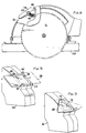
- the viewing window of the present invention is movable between a closed position, as shown in Figure 2, and an open position, as shown in Figure 3.
- spring 42 is slightly compressed, biasing window assembly 31 to the closed position sufficiently to generally maintain that position.
- Window assembly 31 can be moved to the open position by applying an external force outwardly from saw guard 26.
- the window assembly 31 then rotates about its axis to partially expose aperture 46.
- Opening window assembly 31 causes spring 42 to compress and thereby to exert an increased bias on window assembly 31 to the closed position. Further opening of window assembly 31 is prevented when pin 41 contacts stop pin 38. If pin 41 deflects downwardly due to increased pressure, fully compressed spring 42 will also prevent further opening of the window.
- window assembly 31 In the open position, the inside portion of window 32 may be cleared of dust by a brush or other cleaning instrument. After cleaning operations are complete, window assembly 31 is released and thereupon returns to the closed position through the force exerted by spring 42.
- window assembly 50 comprised of a frame 52 and a window 54, may be biased to the closed portion using a torsion spring 56 as shown in Figure 7.
- window assembly 31 provides easily manufactured and efficient structure to allow easy cleaning of a viewing window.
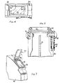
- Figure 8 shows another window assembly embodying the principles of the present invention.
- saw guard 26 is provided with an aperture 59.
- the tabs 60, 62, 64 and 66 Located in saw guard 26 proximate the aperture are the tabs 60, 62, 64 and 66 forming a lateral slot.
- a window 58 is slidably coupled with saw guard 26 by insertion into the slot formed by tabs 60, 62, 64 and 66. Window 58 is sufficiently larger than the aperture to enable the window to slide a sufficient distance for cleaning.
- window 58 slides laterally in the direction of the arrow shown in Figure 8 to substantially expose the portion of the window 58 that had previously covered aperture 59 as shown in broken lines. This portion of the window may be cleaned with a brush or other appropriate material.
- Figure 9 shows another window assembly embodying the principles of the present invention.
- saw guard 26 is provided with an aperture 72 covered by a window 68.
- a pivot pin 70 or other suitable fastener passes through window 68 and through an aperture in the periphery of saw guard 26.
- both window 68 and aperture 72 are preferably triangular shaped.
- Window 68 is furthermore larger than aperture 72 and is able to move from side to side. In operation, an external force is applied to window 68 causing it to pivot a desired distance in the direction of the force. Because window 68 is larger in size than aperture 72, the portion of window 68 previously covering the aperture can be exposed for cleaning as shown by the broken lines in Figure 9.
- Figure 10 shows another window assembly embodying the principles of the present invention.
- a first aperture 76 in saw guard 26 is covered by a window 74.
- Saw guard 26 is further provided with a second aperture 78 proximate and generally perpendicular to aperture 76.
- Aperture 78 can be covered by a removable plug 80. In operation, plug 80 is removed to enable a cleaning tool or compressed air to be introduced through aperture 78 to dislodge dust from the underside of window 74.
- FIG 11 shows another window assembly embodying the principles of the present invention.
- saw guard 26 is provided with an aperture 82.
- a window assembly 83 is adapted to be coupled with saw guard 26.
- Window assembly 83 is comprised of a transparent elongated, planar element 84 having planar ribs 86, 88, 90 and 92 disposed longitudinally on, and perpendicular to, planar element 84.
- Pivot pins 94 and 96 are located on opposite ends of element 84 along its longitudinal centre axis.
- Pin guides 98 and 100 are provided in saw guard 26 to complementally receive pins 94 and 96.
- a pin retainer 102 is placed over pivot pin 94 to retain its position in pin guide 98.
- Pin retainer 102 is held in place by fasteners 104 and 106.
- a pin retainer 108 is placed over pivot pin 96 to retain its position in pin guide 100.
- Pin retainer 108 is held in place by fasteners 110 and 112.
- window assembly 83 is shown in a closed position in Figure 12, whereby element 84 covers aperture 82.
- Window assembly 83 can be rotated about its longitudinal axis defined by pins 94 and 96 to permit cleaning.
- planar ribs 86, 88, 90 and 92 serve to minimise exposure of aperture 82.
- FIGS 13(a) and 13(b) show another window assembly embodying the principles of the present invention.
- saw guard 26 is provided with a housing 113 with an aperture 114 formed therein and arranged to be substantially flush with the contour of the saw guard 26.
- a further aperture 116 is formed proximate and generally perpendicular to aperture 114.
- the aperture 114 is formed so as to be standing slightly proud of the general periphery of saw guard 26. This is so that a cover member 118 can be held within the aperture 114.
- the cover member 118 extends in a direction generally orthogonal to the axis of rotation of the saw 21 and is at least twice the length of the aperture 114 itself in this direction. Furthermore, the cover member 118 is able to move along this direction within the aperture 114.
- the end 120 of the cover member 118 adjacent the aperture 116 is formed with a downwardly facing ramp 122. This ramp 122 is formed to ensure that when the cover member 118 is fully retracted within the aperture 114, it sits flush with the outer surface of the guard 26.
- Movement of the cover member 118 within the aperture is controlled by a manually operable switch 124.
- the switch 124 couples directly to an edge of the cover member 118 and so movement of the switch 124 in a direction as shown by the arrows in the Figure causes the cover member 118 to move.
- the switch is confined to move along a recess 126 (not shown) also formed within the guard 26.
Landscapes
- Life Sciences & Earth Sciences (AREA)
- Engineering & Computer Science (AREA)
- Mechanical Engineering (AREA)
- Wood Science & Technology (AREA)
- Forests & Forestry (AREA)
- Sawing (AREA)
- Sampling And Sample Adjustment (AREA)
Applications Claiming Priority (2)
| Application Number | Priority Date | Filing Date | Title |
|---|---|---|---|
| US08/655,803 US5822864A (en) | 1996-05-31 | 1996-05-31 | Viewing window for circular saw guard |
| US655803 | 1996-05-31 |
Publications (3)
| Publication Number | Publication Date |
|---|---|
| EP0810071A2 true EP0810071A2 (de) | 1997-12-03 |
| EP0810071A3 EP0810071A3 (de) | 1998-09-23 |
| EP0810071B1 EP0810071B1 (de) | 2004-07-28 |
Family
ID=24630426
Family Applications (1)
| Application Number | Title | Priority Date | Filing Date |
|---|---|---|---|
| EP19970303589 Expired - Lifetime EP0810071B1 (de) | 1996-05-31 | 1997-05-27 | Kreisägeschutzhaube mit Sichtfenster |
Country Status (5)
| Country | Link |
|---|---|
| US (3) | US5822864A (de) |
| EP (1) | EP0810071B1 (de) |
| CN (1) | CN1083743C (de) |
| CA (1) | CA2204090A1 (de) |
| DE (1) | DE69729978T2 (de) |
Cited By (6)
| Publication number | Priority date | Publication date | Assignee | Title |
|---|---|---|---|---|
| US6055734A (en) * | 1999-03-04 | 2000-05-02 | Ryobi North America, Inc. | Circular saw with blade viewing window |
| EP1110653A2 (de) * | 1999-02-23 | 2001-06-27 | Black & Decker Inc. | Fensterverriegelungsmechanismus für motorisiertes Werkzeug |
| GB2340445B (en) * | 1998-08-14 | 2003-07-02 | Milwaukee Electric Tool Corp | Improved circular saw |
| EP0974415A3 (de) * | 1998-07-21 | 2003-11-19 | Black & Decker Inc. | Kreissäge mit einer Sägeblattausrichtvorrichtung und Späneabfuhr |
| EP2143533A1 (de) * | 2008-07-07 | 2010-01-13 | Panasonic Electric Works Co., Ltd. | Elektrosäge |
| EP3424656A1 (de) * | 2017-05-22 | 2019-01-09 | Festool GmbH | Schutzabdeckung für eine säge und damit ausgestattete säge |
Families Citing this family (31)
| Publication number | Priority date | Publication date | Assignee | Title |
|---|---|---|---|---|
| US5822864A (en) | 1996-05-31 | 1998-10-20 | Black & Decker, Inc. | Viewing window for circular saw guard |
| USD427874S (en) * | 1999-06-09 | 2000-07-11 | Makita Corporation | Circular saw |
| US6167626B1 (en) * | 1999-07-30 | 2001-01-02 | S-B Power Tool Company | Dust collection port for use with a saw |
| US6543143B2 (en) | 2001-04-06 | 2003-04-08 | Black & Decker Inc. | Metal cutting circular saw with integral sight window |
| US6755107B2 (en) * | 2001-05-18 | 2004-06-29 | One World Technologies Lmt. | Miter saw having a light beam alignment system |
| US7020970B1 (en) * | 2001-10-23 | 2006-04-04 | James Welch | Saw guard system |
| US20070180710A1 (en) * | 2002-04-03 | 2007-08-09 | Keith Moore | Metal cutting circular saw with integral sight window |
| DE10224837A1 (de) * | 2002-06-05 | 2004-01-08 | Robert Bosch Gmbh | Werkzeugmaschine |
| US20030233921A1 (en) * | 2002-06-19 | 2003-12-25 | Garcia Jaime E. | Cutter with optical alignment system |
| US20040060178A1 (en) * | 2002-10-01 | 2004-04-01 | Mark Willer | Circular saw |
| USD489591S1 (en) | 2002-10-01 | 2004-05-11 | Milwaukee Electric Tool Corporation | Circular saw |
| US20070186741A1 (en) * | 2003-06-23 | 2007-08-16 | Buck William C | Table saw guard assembly |
| US20040255745A1 (en) * | 2003-06-23 | 2004-12-23 | One World Technologies Limited | Table saw guard assembly |
| JP2008531315A (ja) * | 2005-03-04 | 2008-08-14 | オーエスジー・パワー・ツールズ・インコーポレーテッド | 動力付きパイプカッタ及び処理工具 |
| US20060090354A1 (en) * | 2005-03-28 | 2006-05-04 | Gongola Andrew G | Power tool, such as a circular saw |
| US20070062048A1 (en) * | 2005-09-21 | 2007-03-22 | Motomax Electric Co., Ltd. | Observation device for portable circular saws |
| US20080168667A1 (en) * | 2005-11-02 | 2008-07-17 | David Spinato | Portable cutting device with guiding guard |
| US20110039042A1 (en) * | 2009-08-17 | 2011-02-17 | Laurie Johansen | Precious metal thin-film laminate (PMTL) |
| US20110219628A1 (en) * | 2010-03-11 | 2011-09-15 | Ryan Harrison | Power tool with debris collection assembly |
| EP2576114B1 (de) | 2010-06-03 | 2018-10-10 | Milwaukee Electric Tool Corporation | Werkstückschutz und klingenschutz für eine bandsäge |
| CN202174614U (zh) * | 2010-08-27 | 2012-03-28 | 泉峰(中国)贸易有限公司 | 链锯 |
| US9610704B2 (en) | 2012-12-11 | 2017-04-04 | Robert Bosch Tool Corporation | Circular saw blade guard with scratch-resistant panel |
| US20140260870A1 (en) * | 2013-03-15 | 2014-09-18 | Oav Equipment & Tools, Inc. | Viewing window for band saw machine |
| CN105021766A (zh) * | 2015-08-03 | 2015-11-04 | 南京理工大学 | 一种便于擦拭激光透镜与观察窗的耐高压燃烧室 |
| JP6890965B2 (ja) * | 2016-12-15 | 2021-06-18 | 株式会社マキタ | 携帯用切断機 |
| CN207189852U (zh) | 2017-06-05 | 2018-04-06 | 米沃奇电动工具公司 | 台锯 |
| US10875109B1 (en) | 2018-04-30 | 2020-12-29 | Kreg Enterprises, Inc. | Adaptive cutting system |
| TWI736312B (zh) * | 2020-06-05 | 2021-08-11 | 聖傑機器工業股份有限公司 | 使用稜鏡反射鋸切影像之圓鋸機 |
| CN112109152A (zh) * | 2020-10-10 | 2020-12-22 | 阜南县嘉盛柳木工艺品有限公司 | 一种柳木工艺品加工用手持式剪裁设备 |
| US11628587B2 (en) * | 2021-02-24 | 2023-04-18 | Techtronic Cordless Gp | Floor saw with blade guard |
| US20230294184A1 (en) * | 2022-03-18 | 2023-09-21 | Milwaukee Electric Tool Corporation | Track saw |
Citations (3)
| Publication number | Priority date | Publication date | Assignee | Title |
|---|---|---|---|---|
| US1830579A (en) * | 1930-01-30 | 1931-11-03 | Wappat Inc | Electric handsaw |
| DE3104340A1 (de) * | 1980-03-06 | 1982-02-25 | AEG Power Tool Corp. (APTC), 06360 Norwich, Conn. | Tragbare kreissaege |
| US4875398A (en) * | 1988-01-15 | 1989-10-24 | Atlantic Richfield Company | Retractable dust control hood and guard for rotary table saw |
Family Cites Families (53)
| Publication number | Priority date | Publication date | Assignee | Title |
|---|---|---|---|---|
| DE498325C (de) | 1930-05-21 | Weingarten Vorm Hch Schatz A G | Niederhalter an Scheren mit Fingerschutzeinrichtung | |
| US1312651A (en) * | 1919-08-12 | waiters | ||
| US1037843A (en) | 1911-10-30 | 1912-09-10 | David S Ackley | Saw-guard |
| US1071049A (en) * | 1913-01-27 | 1913-08-26 | Stephen T Hill | Emery-wheel guard. |
| US1099588A (en) | 1913-03-03 | 1914-06-09 | Thomas E Nicholson | Saw-guard. |
| US1780173A (en) * | 1922-09-25 | 1930-11-04 | Stanley Works | Portable tool |
| US1789357A (en) | 1929-10-09 | 1931-01-20 | Ferry Louis | Saw guard |
| US2183675A (en) * | 1938-05-16 | 1939-12-19 | Griebling Edward William | Saw guard |
| GB558537A (en) * | 1942-11-13 | 1944-01-10 | Reliance Sheet Metal Works Ltd | Machinery guard |
| US2368109A (en) * | 1943-06-07 | 1945-01-30 | Brown Brockmeyer Co | Curved eyeshield for grinders |
| US2491035A (en) * | 1945-07-27 | 1949-12-13 | Deacon Herbert George | Machine tool guard |
| US2795248A (en) * | 1955-01-11 | 1957-06-11 | Dormeyer Corp | Eyeguard for power saw |
| US2876810A (en) * | 1958-03-04 | 1959-03-10 | Joseph M Peterson | Point of operation saw guard |
| DE1253443B (de) | 1962-05-29 | 1967-11-02 | Clemens Baeurle | Schutz- bzw. Sperreinrichtung fuer Kreissaegen |
| US3249134A (en) * | 1964-01-30 | 1966-05-03 | Wilton Corp | Saw and dado guard |
| GB1032816A (en) * | 1964-08-19 | 1966-06-15 | G & M Power Plant Co Ltd | Improvements in power driven pruning saws |
| US3504716A (en) * | 1966-12-28 | 1970-04-07 | Stanley Works | Power tool and guide therefor |
| US3662796A (en) * | 1970-11-06 | 1972-05-16 | Nello Batistelli | Sawdust deflector for portable saw |
| JPS4914598A (de) * | 1972-05-19 | 1974-02-08 | ||
| US3805658A (en) * | 1972-07-24 | 1974-04-23 | Whitney Corp W | Punch press with safety door |
| US3837383A (en) * | 1972-11-09 | 1974-09-24 | K Ko | Dust collector and safety guard |
| US3880032A (en) * | 1973-08-22 | 1975-04-29 | Dwight C Green | Feeler operated saw guard |
| JPS5750716B2 (de) * | 1973-11-14 | 1982-10-28 | ||
| JPS5134787A (ja) * | 1974-09-18 | 1976-03-24 | Hitachi Ltd | Maikurohasokuteisochi |
| JPS5181492A (de) * | 1975-01-14 | 1976-07-16 | Personal Products Co | |
| US3990145A (en) * | 1975-06-25 | 1976-11-09 | Rubin Francis S | Rake and hand shield for hedge trimmers |
| JPS53135687A (en) * | 1977-04-30 | 1978-11-27 | Hiroshi Kawakami | Receipt printer for taxi |
| US4098033A (en) * | 1977-09-29 | 1978-07-04 | Mann Douglass M | Sand blasting apparatus |
| US4322067A (en) | 1978-12-11 | 1982-03-30 | Philip Morris Incorporated | Article transfer apparatus |
| US4257297A (en) | 1979-01-31 | 1981-03-24 | Peter Nidbella | Circular saw with visual cut line indicator |
| US4241505A (en) * | 1979-05-21 | 1980-12-30 | Johns-Manville Corporation | Dust shroud for portable circular saw |
| JPS5615619A (en) * | 1979-07-20 | 1981-02-14 | Kosumo Konsarutantsu Kk | Plant cultivation |
| JPS5669402A (en) * | 1979-11-09 | 1981-06-10 | Hitachi Ltd | Structure of blade train with shroud |
| JPS5669403A (en) * | 1979-11-12 | 1981-06-10 | Hitachi Ltd | Structure for preventing vibration of rotor of axial-flow machine |
| US4450627A (en) * | 1981-07-06 | 1984-05-29 | Shindaiwa Kogyo Co., Ltd. | Device for determining a correct sawing position for a portable rotary sawing machine |
| DE3127274A1 (de) * | 1981-07-10 | 1983-01-27 | Michael Designer Wannert (grad.), 4811 Oerlinghausen | Schleifmaschine |
| DE3303734C2 (de) * | 1983-02-04 | 1985-11-07 | Kress-elektrik GmbH & Co, Elektromotorenfabrik, 7457 Bisingen | Oberfräse, insbesondere Elektrohandoberfräse |
| US4543718A (en) * | 1984-02-01 | 1985-10-01 | Twin City Surgical, Inc. | Cast cutter apparatus |
| US4675999A (en) * | 1984-11-16 | 1987-06-30 | Hitachi Koki Company, Ltd. | Portable power tool equipped with dust collector |
| US4892022A (en) * | 1988-09-20 | 1990-01-09 | Robert Bosch Power Tool Corporation | Safety guard for sawing power tool particularly mitre saw |
| US5046255A (en) | 1989-11-27 | 1991-09-10 | Lebreux Michel F | Air deflector for circular saw |
| US5084972A (en) | 1991-01-25 | 1992-02-04 | Waugh Ricky L | Device for collecting dust from a portable circular saw |
| US5123317A (en) * | 1991-03-20 | 1992-06-23 | Ryobi Motor Products Corp. | Support structure for a table saw blade assembly |
| US5159759A (en) * | 1991-06-26 | 1992-11-03 | Fringer Daniel L | Debris shield for a hand held power saw |
| US5199343A (en) | 1991-10-09 | 1993-04-06 | Black & Decker Inc. | Power saw with louvered blade guard |
| US5440815A (en) * | 1992-04-13 | 1995-08-15 | Inkster; Kevin R. | Guide for rotary cutter tools |
| US5375495A (en) | 1992-05-18 | 1994-12-27 | Porter-Cable Corporation | Optical alignment system for circular power saws |
| JP3336036B2 (ja) * | 1992-05-26 | 2002-10-21 | 松下電工株式会社 | 電動丸鋸 |
| DE4224094A1 (de) * | 1992-07-22 | 1994-01-27 | Bosch Gmbh Robert | Handsäge mit Absaugvorrichtung |
| DE4393469C2 (de) * | 1992-07-28 | 1999-07-22 | Matsushita Electric Works Ltd | Pendelhub-Stichsäge |
| US5822864A (en) * | 1996-05-31 | 1998-10-20 | Black & Decker, Inc. | Viewing window for circular saw guard |
| US5794351A (en) * | 1996-05-31 | 1998-08-18 | Black & Decker, Inc. | Window assembly and lower saw guard for circular saw |
| JP4119601B2 (ja) * | 2000-07-07 | 2008-07-16 | 日立工機株式会社 | 携帯用丸鋸 |
-
1996
- 1996-05-31 US US08/655,803 patent/US5822864A/en not_active Expired - Lifetime
-
1997
- 1997-04-30 CA CA 2204090 patent/CA2204090A1/en not_active Abandoned
- 1997-05-27 EP EP19970303589 patent/EP0810071B1/de not_active Expired - Lifetime
- 1997-05-27 DE DE1997629978 patent/DE69729978T2/de not_active Expired - Fee Related
- 1997-05-30 CN CN97112914A patent/CN1083743C/zh not_active Expired - Fee Related
-
1998
- 1998-07-16 US US09/118,118 patent/US6237230B1/en not_active Expired - Lifetime
-
2001
- 2001-05-25 US US09/864,500 patent/US6502316B2/en not_active Expired - Lifetime
Patent Citations (3)
| Publication number | Priority date | Publication date | Assignee | Title |
|---|---|---|---|---|
| US1830579A (en) * | 1930-01-30 | 1931-11-03 | Wappat Inc | Electric handsaw |
| DE3104340A1 (de) * | 1980-03-06 | 1982-02-25 | AEG Power Tool Corp. (APTC), 06360 Norwich, Conn. | Tragbare kreissaege |
| US4875398A (en) * | 1988-01-15 | 1989-10-24 | Atlantic Richfield Company | Retractable dust control hood and guard for rotary table saw |
Cited By (8)
| Publication number | Priority date | Publication date | Assignee | Title |
|---|---|---|---|---|
| EP0974415A3 (de) * | 1998-07-21 | 2003-11-19 | Black & Decker Inc. | Kreissäge mit einer Sägeblattausrichtvorrichtung und Späneabfuhr |
| GB2340445B (en) * | 1998-08-14 | 2003-07-02 | Milwaukee Electric Tool Corp | Improved circular saw |
| EP1110653A2 (de) * | 1999-02-23 | 2001-06-27 | Black & Decker Inc. | Fensterverriegelungsmechanismus für motorisiertes Werkzeug |
| EP1110653A3 (de) * | 1999-02-23 | 2003-06-11 | Black & Decker Inc. | Fensterverriegelungsmechanismus für motorisiertes Werkzeug |
| US6055734A (en) * | 1999-03-04 | 2000-05-02 | Ryobi North America, Inc. | Circular saw with blade viewing window |
| EP2143533A1 (de) * | 2008-07-07 | 2010-01-13 | Panasonic Electric Works Co., Ltd. | Elektrosäge |
| US8056244B2 (en) | 2008-07-07 | 2011-11-15 | Panasonic Electric Works Co., Ltd. | Electric saw |
| EP3424656A1 (de) * | 2017-05-22 | 2019-01-09 | Festool GmbH | Schutzabdeckung für eine säge und damit ausgestattete säge |
Also Published As
| Publication number | Publication date |
|---|---|
| EP0810071B1 (de) | 2004-07-28 |
| CN1083743C (zh) | 2002-05-01 |
| US6237230B1 (en) | 2001-05-29 |
| EP0810071A3 (de) | 1998-09-23 |
| DE69729978T2 (de) | 2004-12-16 |
| DE69729978D1 (de) | 2004-09-02 |
| US20010022027A1 (en) | 2001-09-20 |
| CN1169896A (zh) | 1998-01-14 |
| CA2204090A1 (en) | 1997-11-30 |
| US5822864A (en) | 1998-10-20 |
| US6502316B2 (en) | 2003-01-07 |
Similar Documents
| Publication | Publication Date | Title |
|---|---|---|
| EP0810071B1 (de) | Kreisägeschutzhaube mit Sichtfenster | |
| EP1400296B1 (de) | Staubabsaugung für eine Gehrungssäge | |
| US9101993B2 (en) | Portable cutter | |
| US7223163B2 (en) | Cover device for a power tool | |
| US6055734A (en) | Circular saw with blade viewing window | |
| EP0985480A2 (de) | Einsatzplatte für ein Werkzeug | |
| EP1236530B1 (de) | Blattaufspannvorrichtung für ein in axialer Richtung hin- und herbewegbares Kraftwerkzeug | |
| US5918522A (en) | Radial arm saw blade guard | |
| US7526866B2 (en) | Variable dust chute for circular saws | |
| US20030172789A1 (en) | Circular sawing machine having a hidden-type infrared guide device | |
| CA2756374C (en) | Staple gun wire guide | |
| JPH03292990A (ja) | かみそり機構 | |
| EP0882537B1 (de) | Sägemaschine mit hin- und hergehendem Sägeblatt und Sägeblattspannvorrichtung mit mehrfacher Sägeblattspannposition | |
| EP0561575B1 (de) | Kreissäge mit unterer Schutzhaube und Spanumlenker | |
| EP1110653B1 (de) | Fensterverriegelungsmechanismus für motorisiertes Werkzeug | |
| CN107552872B (zh) | 切割工具 | |
| GB2393683A (en) | Circular saw with removable blade cover | |
| US20070034064A1 (en) | Dust-collecting unit and electric tool having the same | |
| US5171112A (en) | Key cutting apparatus | |
| GB2195295A (en) | A combined envelope opener and pencil sharpener unit | |
| JP2008188715A (ja) | 直条部材の切断装置 | |
| AU2004203654A1 (en) | Sanding apparatus | |
| WO1996005027A1 (en) | A safety knife or cutter | |
| PT1428616E (pt) | Plaina | |
| PT1428615E (pt) | Plaina |
Legal Events
| Date | Code | Title | Description |
|---|---|---|---|
| PUAI | Public reference made under article 153(3) epc to a published international application that has entered the european phase |
Free format text: ORIGINAL CODE: 0009012 |
|
| AK | Designated contracting states |
Kind code of ref document: A2 Designated state(s): DE FR GB IT NL SE |
|
| PUAL | Search report despatched |
Free format text: ORIGINAL CODE: 0009013 |
|
| AK | Designated contracting states |
Kind code of ref document: A3 Designated state(s): DE FR GB IT NL SE |
|
| 17P | Request for examination filed |
Effective date: 19990220 |
|
| 17Q | First examination report despatched |
Effective date: 20020806 |
|
| GRAP | Despatch of communication of intention to grant a patent |
Free format text: ORIGINAL CODE: EPIDOSNIGR1 |
|
| GRAS | Grant fee paid |
Free format text: ORIGINAL CODE: EPIDOSNIGR3 |
|
| GRAA | (expected) grant |
Free format text: ORIGINAL CODE: 0009210 |
|
| AK | Designated contracting states |
Kind code of ref document: B1 Designated state(s): DE FR GB IT NL SE |
|
| REG | Reference to a national code |
Ref country code: GB Ref legal event code: FG4D |
|
| REG | Reference to a national code |
Ref country code: SE Ref legal event code: TRGR |
|
| REF | Corresponds to: |
Ref document number: 69729978 Country of ref document: DE Date of ref document: 20040902 Kind code of ref document: P |
|
| ET | Fr: translation filed | ||
| PLBE | No opposition filed within time limit |
Free format text: ORIGINAL CODE: 0009261 |
|
| STAA | Information on the status of an ep patent application or granted ep patent |
Free format text: STATUS: NO OPPOSITION FILED WITHIN TIME LIMIT |
|
| 26N | No opposition filed |
Effective date: 20050429 |
|
| PGFP | Annual fee paid to national office [announced via postgrant information from national office to epo] |
Ref country code: SE Payment date: 20080529 Year of fee payment: 12 Ref country code: NL Payment date: 20080524 Year of fee payment: 12 Ref country code: DE Payment date: 20080630 Year of fee payment: 12 |
|
| PGFP | Annual fee paid to national office [announced via postgrant information from national office to epo] |
Ref country code: IT Payment date: 20080528 Year of fee payment: 12 |
|
| PGFP | Annual fee paid to national office [announced via postgrant information from national office to epo] |
Ref country code: GB Payment date: 20080529 Year of fee payment: 12 |
|
| GBPC | Gb: european patent ceased through non-payment of renewal fee |
Effective date: 20090527 |
|
| NLV4 | Nl: lapsed or anulled due to non-payment of the annual fee |
Effective date: 20091201 |
|
| PG25 | Lapsed in a contracting state [announced via postgrant information from national office to epo] |
Ref country code: NL Free format text: LAPSE BECAUSE OF NON-PAYMENT OF DUE FEES Effective date: 20091201 |
|
| REG | Reference to a national code |
Ref country code: FR Ref legal event code: ST Effective date: 20100129 |
|
| PG25 | Lapsed in a contracting state [announced via postgrant information from national office to epo] |
Ref country code: FR Free format text: LAPSE BECAUSE OF NON-PAYMENT OF DUE FEES Effective date: 20090602 |
|
| PGFP | Annual fee paid to national office [announced via postgrant information from national office to epo] |
Ref country code: FR Payment date: 20080519 Year of fee payment: 12 |
|
| PG25 | Lapsed in a contracting state [announced via postgrant information from national office to epo] |
Ref country code: GB Free format text: LAPSE BECAUSE OF NON-PAYMENT OF DUE FEES Effective date: 20090527 |
|
| PG25 | Lapsed in a contracting state [announced via postgrant information from national office to epo] |
Ref country code: DE Free format text: LAPSE BECAUSE OF NON-PAYMENT OF DUE FEES Effective date: 20091201 |
|
| PG25 | Lapsed in a contracting state [announced via postgrant information from national office to epo] |
Ref country code: IT Free format text: LAPSE BECAUSE OF NON-PAYMENT OF DUE FEES Effective date: 20090527 |
|
| PG25 | Lapsed in a contracting state [announced via postgrant information from national office to epo] |
Ref country code: SE Free format text: LAPSE BECAUSE OF NON-PAYMENT OF DUE FEES Effective date: 20090528 |