EP0809927B1 - Embrayage articulé et séparable, à griffes - Google Patents
Embrayage articulé et séparable, à griffes Download PDFInfo
- Publication number
- EP0809927B1 EP0809927B1 EP97106978A EP97106978A EP0809927B1 EP 0809927 B1 EP0809927 B1 EP 0809927B1 EP 97106978 A EP97106978 A EP 97106978A EP 97106978 A EP97106978 A EP 97106978A EP 0809927 B1 EP0809927 B1 EP 0809927B1
- Authority
- EP
- European Patent Office
- Prior art keywords
- parts
- clutch
- frame parts
- separable
- claw coupling
- Prior art date
- Legal status (The legal status is an assumption and is not a legal conclusion. Google has not performed a legal analysis and makes no representation as to the accuracy of the status listed.)
- Expired - Lifetime
Links
- 210000000078 claw Anatomy 0.000 title claims abstract description 27
- 230000008878 coupling Effects 0.000 title abstract description 30
- 238000010168 coupling process Methods 0.000 title abstract description 30
- 238000005859 coupling reaction Methods 0.000 title abstract description 30
- 238000010276 construction Methods 0.000 claims 1
- 230000000903 blocking effect Effects 0.000 description 4
- 238000000034 method Methods 0.000 description 2
- 230000006978 adaptation Effects 0.000 description 1
- 238000005452 bending Methods 0.000 description 1
- 210000000056 organ Anatomy 0.000 description 1
- 238000009987 spinning Methods 0.000 description 1
- 230000001360 synchronised effect Effects 0.000 description 1
Images


Classifications
-
- F—MECHANICAL ENGINEERING; LIGHTING; HEATING; WEAPONS; BLASTING
- F16—ENGINEERING ELEMENTS AND UNITS; GENERAL MEASURES FOR PRODUCING AND MAINTAINING EFFECTIVE FUNCTIONING OF MACHINES OR INSTALLATIONS; THERMAL INSULATION IN GENERAL
- F16D—COUPLINGS FOR TRANSMITTING ROTATION; CLUTCHES; BRAKES
- F16D3/00—Yielding couplings, i.e. with means permitting movement between the connected parts during the drive
- F16D3/16—Universal joints in which flexibility is produced by means of pivots or sliding or rolling connecting parts
- F16D3/18—Universal joints in which flexibility is produced by means of pivots or sliding or rolling connecting parts the coupling parts (1) having slidably-interengaging teeth
-
- F—MECHANICAL ENGINEERING; LIGHTING; HEATING; WEAPONS; BLASTING
- F16—ENGINEERING ELEMENTS AND UNITS; GENERAL MEASURES FOR PRODUCING AND MAINTAINING EFFECTIVE FUNCTIONING OF MACHINES OR INSTALLATIONS; THERMAL INSULATION IN GENERAL
- F16H—GEARING
- F16H1/00—Toothed gearings for conveying rotary motion
- F16H1/006—Toothed gearings for conveying rotary motion the driving and driven axes being designed to assume variable positions relative to one another during operation
Definitions
- the invention relates to a separable claw coupling, in particular for Drive of hay machines with articulated frame parts, the pivot axis of the frame joint at a distance from the axis of rotation the clutch is arranged.
- the invention is therefore based on the object of a separable articulated claw coupling of the type mentioned in such a way that when swiveling the clutch in the working position the meshing of the claw coupling parts regardless of the position of these parts relative to each other is possible.
- the claw coupling parts are first engaged, which also automatically rotates the gyro units into one position be in which the tines of the one spinning top in gaps between tines of the intervene in another gyro so that when swiveling further the mentioned one Blocking can never take place.
- the driver bodies are like this designed to be able to bend the frame parts during operation are always fully engaged against each other and thus a rotary movement as possible can transmit without play.
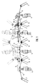
- the rotary tedder shown schematically in Fig. 1 comprises a Frame 1 with two inner frame parts 2 and two articulated, can be swiveled upwards into the dashed driving or non-use position outer frame parts 3, an impeller 4 on each of the frame parts 2 and 3 and a gyro unit 5 with one another meshing in the operating position according to FIG. 1 engaging tine groups 6, 7 is arranged.
- an impeller 4 on each of the frame parts 2 and 3 and a gyro unit 5 with one another meshing in the operating position according to FIG. 1 engaging tine groups 6, 7 is arranged.
- From a common Not shown drive in the drawbar to the towing vehicle are the individual Gyro 5 driven by drive shafts 8, 9 which are in the area of the joints 10 between the inner and outer frame parts 2, 3 via separable articulated Claw couplings are interconnected.
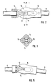
- the substantially identical claw coupling parts 11 and 12 include in the illustrated embodiment, two for each drive shaft 8, 9 parallel spaced spindle-shaped driver bodies 13 and 14, according to a preferred embodiment shown in FIG. 7, one of the Driver body 13 'is shorter than the other driver body 13, so that when engaging, as shown in Fig. 6, not in one position can hit both tips of the driver body and each other therefore the coupling halves do not mutually screw into the coupling position can hinder.
- Fig. 5 it is indicated that the shape of the spindle-shaped driver body 13, 14 is chosen so that taking into account the possible bends in operation the frame parts 2, 3 against each other, resulting in a corresponding Bending the drive shafts 8, 9 leads, the driver body always fully in Stand in engagement and can thus transmit a rotational movement with as little play as possible.
- Fig. 4 it can also be seen that the training is made such that the pivot angle a of the outer frame part 3 with respect to the inner frame part 2, in which the engagement or disengagement of the driver bodies 13, 14 takes place, is smaller than the swivel angle from which the tines 6, 7 to the Frame parts 2 and 3 attached gyro units 5 interlock. Thereby it is ensured that the driver bodies 13, 13 '; 14 of the claw coupling parts 11, 12 when moving together rotated by 180 ° against each other Have brought position according to FIG.
Landscapes
- Engineering & Computer Science (AREA)
- General Engineering & Computer Science (AREA)
- Mechanical Engineering (AREA)
- Soil Working Implements (AREA)
- Seal Device For Vehicle (AREA)
- Flanged Joints, Insulating Joints, And Other Joints (AREA)
- Clamps And Clips (AREA)
- Replacement Of Web Rolls (AREA)
- Agricultural Machines (AREA)
Claims (3)
- Accouplement à griffes séparable, notamment destiné à l'entraínement de machines de fenaison comprenant des parties de châssis reliées les unes aux autres de manière articulée, l'axe de pivotement de l'articulation de châssis étant placé à distance de l'axe de rotation de l'accouplement, caractérisé en ce que chacune des deux parties d'accouplement à griffes (11, 12) de construction sensiblement identique, ne comporte que deux corps d'entraínement (13, 13'; 14) espacés, en forme de broche et sensiblement parallèles à l'arbre d'entraínement respectif (8, 9), et en ce que les corps d'entraínement (13, 13'; 14) sont conçus de façon telle qu'ils soient en prise réciproque totale pour toutes les positions angulaires possibles en fonctionnement, des parties de châssis (2, 3) l'une par rapport à l'autre.
- Accouplement à griffes séparable selon la revendication 1, caractérisé en ce que l'angle de pivotement α des parties de châssis (2, 3), à partir duquel les parties d'accouplement à griffes (11, 12) sont en prise, est inférieur à l'angle de pivotement à partir duquel les unités de toupie (5) associées interfèrent mutuellement.
- Accouplement à griffes séparable selon l'une des revendications 1 à 2, caractérisé en ce que sur une moitié d'accouplement, au moins un corps d'entraínement (13') est réalisé plus court que l'autre corps d'accouplement (13).
Applications Claiming Priority (2)
| Application Number | Priority Date | Filing Date | Title |
|---|---|---|---|
| DE29609520U | 1996-05-29 | ||
| DE29609520U DE29609520U1 (de) | 1996-05-29 | 1996-05-29 | Trennbare gelenkige Klauenkupplung |
Publications (2)
| Publication Number | Publication Date |
|---|---|
| EP0809927A1 EP0809927A1 (fr) | 1997-12-03 |
| EP0809927B1 true EP0809927B1 (fr) | 2001-02-14 |
Family
ID=8024517
Family Applications (1)
| Application Number | Title | Priority Date | Filing Date |
|---|---|---|---|
| EP97106978A Expired - Lifetime EP0809927B1 (fr) | 1996-05-29 | 1997-04-26 | Embrayage articulé et séparable, à griffes |
Country Status (3)
| Country | Link |
|---|---|
| EP (1) | EP0809927B1 (fr) |
| AT (1) | ATE199114T1 (fr) |
| DE (2) | DE29609520U1 (fr) |
Cited By (1)
| Publication number | Priority date | Publication date | Assignee | Title |
|---|---|---|---|---|
| US12181004B2 (en) | 2021-06-22 | 2024-12-31 | JSI Equipment Solutions LLC | Flexible coupling for a drive train |
Families Citing this family (1)
| Publication number | Priority date | Publication date | Assignee | Title |
|---|---|---|---|---|
| DE202009015958U1 (de) | 2009-11-23 | 2011-04-07 | Kverneland Asa | Drehkupplung und landwirtschaftliche Maschine |
Family Cites Families (5)
| Publication number | Priority date | Publication date | Assignee | Title |
|---|---|---|---|---|
| DE1507338C3 (de) * | 1966-11-19 | 1978-07-13 | Massey-Ferguson Industries Ltd., Toronto, Ontario (Kanada) | Kupplung zum Verbinden des Weltenendes der querliegenden Antriebswelle eines Mähdrescher-Mähtisches mit dem Wellenende der parallelen Antriebswelle des Elevatorteils |
| DE2740911A1 (de) * | 1977-09-10 | 1979-03-22 | Kloeckner Humboldt Deutz Ag | Klauenkupplung |
| NL8800065A (nl) * | 1987-06-23 | 1989-01-16 | Lely Nv C Van Der | Hooibouwmachine. |
| FR2641936B2 (fr) * | 1988-11-21 | 1992-01-03 | Kuhn Sa | |
| FR2740653B1 (fr) * | 1995-11-07 | 1998-01-30 | Kuhn Sa | Machine de fenaison, notamment une faneuse, comportant un bati avec des parties laterales repliables |
-
1996
- 1996-05-29 DE DE29609520U patent/DE29609520U1/de not_active Expired - Lifetime
-
1997
- 1997-04-26 EP EP97106978A patent/EP0809927B1/fr not_active Expired - Lifetime
- 1997-04-26 DE DE59702994T patent/DE59702994D1/de not_active Expired - Fee Related
- 1997-04-26 AT AT97106978T patent/ATE199114T1/de not_active IP Right Cessation
Cited By (1)
| Publication number | Priority date | Publication date | Assignee | Title |
|---|---|---|---|---|
| US12181004B2 (en) | 2021-06-22 | 2024-12-31 | JSI Equipment Solutions LLC | Flexible coupling for a drive train |
Also Published As
| Publication number | Publication date |
|---|---|
| ATE199114T1 (de) | 2001-02-15 |
| DE29609520U1 (de) | 1996-08-29 |
| DE59702994D1 (de) | 2001-03-22 |
| EP0809927A1 (fr) | 1997-12-03 |
Similar Documents
| Publication | Publication Date | Title |
|---|---|---|
| AT389974B (de) | Kreiselheuwerbungsmaschine | |
| EP0277343B1 (fr) | Faucheuse | |
| EP0131853A1 (fr) | Récolteuse de mais | |
| DE60320097T2 (de) | Heuwerbungsmaschine | |
| DE69628598T2 (de) | Heuwerbungsmaschine | |
| DE60003614T2 (de) | Heuerntemaschine mit mindestens einem rotor zum schwaden mit in position verstellbarem leitblech | |
| DE2111227A1 (de) | Maehdrescher | |
| DE102019002828B3 (de) | Mähmaschine | |
| DE68916191T2 (de) | Landmaschine, insbesondere für die Heuwerbung mit einem mehrteiligen schwenkbaren Rahmen. | |
| DE9312222U1 (de) | Heuwerbungsmaschine | |
| EP0291812B1 (fr) | Machine agricole, en particulier un épandeur d'herbe à disque | |
| EP0809927B1 (fr) | Embrayage articulé et séparable, à griffes | |
| EP1769668B1 (fr) | Tête de récolte avec châssis pivotant pour machines agricoles | |
| EP2923541B1 (fr) | Outil porté agricole | |
| DE19620063A1 (de) | Aufhängung und Antriebsanordnung für ein- oder beidseitig an einem Trägerfahrzeug angebrachte Arbeitsaggregate | |
| DE69705337T2 (de) | Heuwerbungsmaschine | |
| DE2844235A1 (de) | Heuwerbungsmaschine | |
| DE3029502C2 (fr) | ||
| DE10021660C2 (de) | Erntemaschine, insbesondere selbstfahrender Feldhäcksler | |
| DE602005005143T2 (de) | Heuwerbungsmaschine | |
| DE910028C (de) | Einrichtung zum Kuppeln des Aufliegers von Sattelschleppern | |
| DE69604317T2 (de) | Heuwerbungsmaschine | |
| EP4344528B1 (fr) | Tête de récolte à montage frontal sur une récolteuse dotée d'une unité de broyage | |
| DE2617970A1 (de) | Heuwerbungsmaschine | |
| EP3823430B1 (fr) | Appareil agricole pourvu d'une transmission à cardan |
Legal Events
| Date | Code | Title | Description |
|---|---|---|---|
| PUAI | Public reference made under article 153(3) epc to a published international application that has entered the european phase |
Free format text: ORIGINAL CODE: 0009012 |
|
| AK | Designated contracting states |
Kind code of ref document: A1 Designated state(s): AT DE FR |
|
| 17P | Request for examination filed |
Effective date: 19980516 |
|
| 17Q | First examination report despatched |
Effective date: 19981014 |
|
| GRAG | Despatch of communication of intention to grant |
Free format text: ORIGINAL CODE: EPIDOS AGRA |
|
| GRAG | Despatch of communication of intention to grant |
Free format text: ORIGINAL CODE: EPIDOS AGRA |
|
| GRAH | Despatch of communication of intention to grant a patent |
Free format text: ORIGINAL CODE: EPIDOS IGRA |
|
| GRAH | Despatch of communication of intention to grant a patent |
Free format text: ORIGINAL CODE: EPIDOS IGRA |
|
| GRAA | (expected) grant |
Free format text: ORIGINAL CODE: 0009210 |
|
| AK | Designated contracting states |
Kind code of ref document: B1 Designated state(s): AT DE FR |
|
| REF | Corresponds to: |
Ref document number: 199114 Country of ref document: AT Date of ref document: 20010215 Kind code of ref document: T |
|
| ET | Fr: translation filed | ||
| REF | Corresponds to: |
Ref document number: 59702994 Country of ref document: DE Date of ref document: 20010322 |
|
| PLBE | No opposition filed within time limit |
Free format text: ORIGINAL CODE: 0009261 |
|
| STAA | Information on the status of an ep patent application or granted ep patent |
Free format text: STATUS: NO OPPOSITION FILED WITHIN TIME LIMIT |
|
| 26N | No opposition filed | ||
| PGFP | Annual fee paid to national office [announced via postgrant information from national office to epo] |
Ref country code: FR Payment date: 20030401 Year of fee payment: 7 |
|
| PGFP | Annual fee paid to national office [announced via postgrant information from national office to epo] |
Ref country code: AT Payment date: 20030424 Year of fee payment: 7 |
|
| PGFP | Annual fee paid to national office [announced via postgrant information from national office to epo] |
Ref country code: DE Payment date: 20030428 Year of fee payment: 7 |
|
| PG25 | Lapsed in a contracting state [announced via postgrant information from national office to epo] |
Ref country code: AT Free format text: LAPSE BECAUSE OF NON-PAYMENT OF DUE FEES Effective date: 20040426 |
|
| PG25 | Lapsed in a contracting state [announced via postgrant information from national office to epo] |
Ref country code: DE Free format text: LAPSE BECAUSE OF NON-PAYMENT OF DUE FEES Effective date: 20041103 |
|
| PG25 | Lapsed in a contracting state [announced via postgrant information from national office to epo] |
Ref country code: FR Free format text: LAPSE BECAUSE OF NON-PAYMENT OF DUE FEES Effective date: 20041231 |
|
| REG | Reference to a national code |
Ref country code: FR Ref legal event code: ST |