EP0809767B1 - Dispositif de support pour tuyaux dans des traversees de mur - Google Patents
Dispositif de support pour tuyaux dans des traversees de mur Download PDFInfo
- Publication number
- EP0809767B1 EP0809767B1 EP96904773A EP96904773A EP0809767B1 EP 0809767 B1 EP0809767 B1 EP 0809767B1 EP 96904773 A EP96904773 A EP 96904773A EP 96904773 A EP96904773 A EP 96904773A EP 0809767 B1 EP0809767 B1 EP 0809767B1
- Authority
- EP
- European Patent Office
- Prior art keywords
- supporting device
- wall
- clamping sleeves
- pivoting
- pivoting clamping
- Prior art date
- Legal status (The legal status is an assumption and is not a legal conclusion. Google has not performed a legal analysis and makes no representation as to the accuracy of the status listed.)
- Expired - Lifetime
Links
Images


Classifications
-
- F—MECHANICAL ENGINEERING; LIGHTING; HEATING; WEAPONS; BLASTING
- F16—ENGINEERING ELEMENTS AND UNITS; GENERAL MEASURES FOR PRODUCING AND MAINTAINING EFFECTIVE FUNCTIONING OF MACHINES OR INSTALLATIONS; THERMAL INSULATION IN GENERAL
- F16L—PIPES; JOINTS OR FITTINGS FOR PIPES; SUPPORTS FOR PIPES, CABLES OR PROTECTIVE TUBING; MEANS FOR THERMAL INSULATION IN GENERAL
- F16L5/00—Devices for use where pipes, cables or protective tubing pass through walls or partitions
- F16L5/02—Sealing
- F16L5/08—Sealing by means of axial screws compressing a ring or sleeve
-
- H—ELECTRICITY
- H02—GENERATION; CONVERSION OR DISTRIBUTION OF ELECTRIC POWER
- H02G—INSTALLATION OF ELECTRIC CABLES OR LINES, OR OF COMBINED OPTICAL AND ELECTRIC CABLES OR LINES
- H02G3/00—Installations of electric cables or lines or protective tubing therefor in or on buildings, equivalent structures or vehicles
- H02G3/22—Installations of cables or lines through walls, floors or ceilings, e.g. into buildings
Definitions
- the invention relates to a support device for pipes in Wall or wall penetrations, ceiling openings or the like, according to the preamble of claim 1.
- a closure part is provided, that between two flange plates a rubber-elastic sealing body has, via an axial bracing of the flange plates on the one hand towards the encircled pipe and on the other hand is so deformable towards the wall opening that the Wall duct has a tight seal.
- the eccentric arrangement of the through holes allows the Carrying out several pipes.
- the support device stands out for pipes by the in the characterizing part of claim 1 specified characteristics.
- Refinements of the support device are based on claims 2 referred to 14.
- the support device has a closure part at least two swivel clamping sleeves, the walls of which are dimensioned in this way are that when assembling a nesting in the axial Direction is possible. At the same time they are each central longitudinal axes defining the inner or outer diameter eccentrically arranged. The inside of the both sleeves will be on the laying provided tube pushed that this encompassed form-fitting is. After that is like a pipe-in-pipe connection the second swivel clamping sleeve pushed over the first and the both components can be placed together in the wall opening be positioned.
- the two can Swivel clamping sleeves are pivoted in opposite directions to one another, that their walls, through training with the eccentric Through holes different wall thickness ranges perform, on the one hand directly in connection intervention arrive and pressed against each other and on the other hand, the outer of the two swivel clamping sleeves The opening gap to the wall opening closes directly.
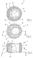
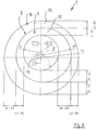
- Fig. 1 is a closure part generally designated 1 for a support device 2 (Fig. 4) shown with a Pipe 3 when laying it in a wall, ceiling or Wall part 4 can be fixed.
- the tube 3 is on the outside comprises of the closure part 1 and simultaneously with this in the mounting position (Fig. 4) seals an opening gap 5.
- FIG. 1 clarifies when viewed together with the basic representations according to FIGS. 6 to 9 the inventive design of the closure part 1, the at least two eccentric through bores 7, 8 having swivel clamping sleeves 9, 10 is formed, which in Direction of a central longitudinal axis 11 of the tube 3 at least in some areas can be pushed into one another such that a subsequent pivoting movement jamming the two Swivel clamping sleeves 9, 10 in a sealing the opening gap 5 Connection intervention is reached.
- the swivel clamping sleeves 9, 10 are of a suitable design made entirely of elastic material, for example Rubber or the like. Formed so that the walls 12, 13 of Swivel clamping sleeves 9, 10 on the one hand directly in the assembly position jammed against each other and on the other hand in the opening gap 5 of the respective wall duct in a sealing Press position on the wall (Fig. 4).
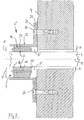
- FIG. 4 clarifies that the cover plate 16 with a the diameter of the opening gap 5 covering outer diameter D is formed so that the Cover plate 16 is supported on the wall 4 and in the mounting position located swivel clamping sleeves 9, 10 an additional, variably adjustable spreading pressure over the at Tensioning the connecting screws 18 effective torque is communicable.
- swivel clamping sleeve 10 can the wall 4 in the area of the implementation with a Lining layer 20 are provided.
- This lining layer 20 is a practical version of one formed in the bushing cast sleeve 21. This can also consist of an elastic material, so that the tightness of the connection engagement in the gap area 5 outer of the two swivel clamping sleeves 10 is improved.
- FIG. 5 is a second embodiment of the support device 2 'shown, the two swivel clamping sleeves 9, 10 on a pipe flange 22 arranged in front of the opening gap 5 are supported. It is in the area of the pipe flange 22
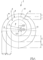
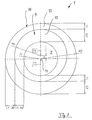
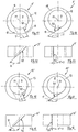
- FIGS. 6 to 9 are several basic representations of the two swivel clamping sleeves 9, 10 located in the connecting position shown in a geometrically simplified version.
- a center point M which is the center point corresponds to the wall duct in the area of the opening gap 5
- 10 eccentricities effective in the assembly position As reference values for the eccentrically arranged ones
- Through holes 7, 8 are respective shift positions the central longitudinal axes M1 and M2 with respect to the central longitudinal axis M illustrated. It is clear that this is in the through hole 7 located pipe (not shown) even then can be included liquid and gas tight, if this relocated outside the central longitudinal plane M of the opening gap 5 and at the same time the eccentric position of the tube 3 can be compensated in the gap 5.
- Swivel clamping sleeves 9, 10 and / or 30 in the area of their respective walls 12, 13, 29 in the direction of the central longitudinal axis 11 conical, so that already in the above Assemble the parts in the axial direction in the area of the adjacent wall surfaces is achievable.
- Swivel clamp sleeves 9 or 10 or 30 can eccentric arrangement of a tube 3 already thereby Gap area are tightly closed that only one of the Swivel clamping sleeves 9 or 10 or 30 introduced and accordingly via a pivoting movement and / or axial pressure is braced (not shown). It is also conceivable that Swivel clamp sleeves to simplify assembly with one or to provide several longitudinal slots or the swivel clamping sleeves several in a row in the axial direction assemble arranged parts.
- the swivel clamping sleeves 9 'and 10' in of a respective individual representation, where their formation with a respective wall area 12 or 13 completely separating longitudinal slot 40, 40 'becomes clear.
- the swivel clamping sleeves 9 ', 10' for a subsequent seal assembly in one Wall opening for example in the area of a flange pipe, also over its larger diameter Flange approach pushed away and in the intended mounting position to be set so that about the effective pressing forces of the longitudinal slot 40, 40 'sufficient is tightly closed (not shown).
- each Longitudinal slots 40 can be slanted T, T ' or R, R '(FIGS. 11 to 18) in the respective wall 9', 10 'run so that the radial and tangential press forces completely in the range of the two adjacent separating surfaces of the longitudinal slot 40 initiated and this reliably over an extended contact area are tight. It is also conceivable that the longitudinal slot 40 ' to train with an arc contour and so the separating and Extend the contact surface in the respective slot area (Fig. 19 to Fig. 22).
Landscapes
- Engineering & Computer Science (AREA)
- General Engineering & Computer Science (AREA)
- Architecture (AREA)
- Civil Engineering (AREA)
- Structural Engineering (AREA)
- Mechanical Engineering (AREA)
- Supports For Pipes And Cables (AREA)
- Building Environments (AREA)
- Rigid Pipes And Flexible Pipes (AREA)
- Joints Allowing Movement (AREA)
Claims (14)
- Dispositif de support pour tuyaux, en particulier pour la pose d'un tuyau dans des traversées de murs, de plafonds ou de parois, qui est muni d'une partie d'obturation (1, 1') constituée de matériau élastique au moins par zones, entourant extérieurement le tuyau (3) en position de montage et étanchant un espace ouvert (5, 5') restant de la traversée, partie d'obturation dont l'orifice de passage recevant le tuyau est agencé de manière excentrée, caractérisé en ce que la partie d'obturation (1, 1') est formée d'au moins deux douilles de serrage pivotantes (9, 10; 30; 9', 10') présentant des orifices de passage respectivement excentrés (7, 8), lesdites douilles pouvant être emboítées l'une dans l'autre au moins par zones dans la direction axiale et pouvant être fixées, via un mouvement pivotant, dans un engagement de liaison étanchant l'espace ouvert (5, 5').
- Dispositif de support selon la revendication 1, caractérisé en ce que, d'une part, les douilles de serrage pivotantes (9, 10; 30; 9', 10') peuvent être serrées respectivement en position de montage directement l'une contre l'autre et, d'autre part, la douille pivotante extérieure (10) s'applique dans la traversée du mur en une position de compression étanche côté paroi.
- Dispositif de support selon la revendication 1, caractérisé en ce que les douilles de serrage pivotantes (9, 10; 30; 9', 10') sont formées respectivement en totalité d'un matériau de gomme élastique.
- Dispositif de support selon l'une quelconque des revendications 1 à 3, caractérisé en ce qu'au moins la douille de serrage pivotante intérieure (9) respective présente dans sa paroi (12) plusieurs orifices de passage (15) à axes parallèles.
- Dispositif de support selon l'une quelconque des revendications 1 à 4, caractérisé en ce que les douilles de serrage pivotantes (9, 10; 30; 9', 10') se trouvant en position de montage sont munies, dans les deux zones d'extrémité, respectivement d'une plaque de recouvrement (16, 17) et celles-ci sont serrées par des vis de fixation (18) traversant l'orifice de passage (15).
- Dispositif de support selon la revendication 5, caractérisé en ce que l'une des plaques de recouvrement (16) a un diamètre externe (D) recouvrant le diamètre de l'espace ouvert (5, 5').
- Dispositif de support selon l'une quelconque des revendications 1 à 6, caractérisé en ce que la douille de serrage pivotante (10) se trouvant à l'extérieur dans la direction radiale dans l'espace ouvert (5, 5') s'appuie sur une couche de garnissage (20) formant la paroi de la traversée.
- Dispositif de support selon la revendication 7, caractérisé en ce que la couche de garnissage (20) se présente sous la forme d'une douille tubulaire (21) scellée dans la traversée.
- Dispositif de support selon la revendication 7 ou 8, caractérisé en ce que la couche de garnissage (20) est formée d'un matériau élastique.
- Dispositif de support selon l'une quelconque des revendications 1 à 9, caractérisé en ce que les douilles de serrage pivotantes (9, 10; 30; 9', 10') sont conformées avec des parois coniques au moins par zones.
- Dispositif de support selon l'une quelconque des revendications 1 à 10, caractérisé en ce que la douille de serrage pivotante (9, 10') est munie, dans la zone de sa paroi (12, 13), d'une fente longitudinale (40, 40') s'étendant sensiblement parallèlement à l'axe longitudinal central (11).
- Dispositif de support selon la revendication 11, caractérisé en ce que la fente longitudinale (40) définit un plan de coupe rectiligne qui présente dans la paroi (12, 13) une position oblique (R, T).
- Dispositif de support selon la revendication 11, caractérisé en ce que la fente longitudinale (40') définit un plan de coupe arqué.
- Dispositif de support selon l'une quelconque des revendications 11 à 13, caractérisé en ce que la fente longitudinale (40, 40') est agencée respectivement dans la zone de la paroi (12, 13) présentant la plus grande épaisseur de matériau.
Applications Claiming Priority (3)
| Application Number | Priority Date | Filing Date | Title |
|---|---|---|---|
| DE29502331U | 1995-02-14 | ||
| DE29502331U DE29502331U1 (de) | 1995-02-14 | 1995-02-14 | Stützvorrichtung für Rohre in Mauerdurchführungen |
| PCT/EP1996/000629 WO1996025616A1 (fr) | 1995-02-14 | 1996-02-14 | Dispositif de support pour tuyaux dans des traversees de mur |
Publications (2)
| Publication Number | Publication Date |
|---|---|
| EP0809767A1 EP0809767A1 (fr) | 1997-12-03 |
| EP0809767B1 true EP0809767B1 (fr) | 1999-08-11 |
Family
ID=8003832
Family Applications (1)
| Application Number | Title | Priority Date | Filing Date |
|---|---|---|---|
| EP96904773A Expired - Lifetime EP0809767B1 (fr) | 1995-02-14 | 1996-02-14 | Dispositif de support pour tuyaux dans des traversees de mur |
Country Status (7)
| Country | Link |
|---|---|
| EP (1) | EP0809767B1 (fr) |
| AT (1) | ATE183296T1 (fr) |
| DE (2) | DE29502331U1 (fr) |
| DK (1) | DK0809767T3 (fr) |
| ES (1) | ES2137668T3 (fr) |
| GR (1) | GR3031249T3 (fr) |
| WO (1) | WO1996025616A1 (fr) |
Families Citing this family (10)
| Publication number | Priority date | Publication date | Assignee | Title |
|---|---|---|---|---|
| DE19736494A1 (de) * | 1997-08-22 | 1999-02-25 | Hauff Technik Gmbh & Co Kg | Dichtpackung zum Einsetzen in eine Maueröffnung zwecks Durchführen von Leitungen |
| DE10248816A1 (de) * | 2002-10-19 | 2004-11-11 | Audi Ag | Verbindungs- und Einstellvorrichtung |
| DE10313306B3 (de) * | 2003-03-25 | 2004-07-01 | Poloplast Gmbh & Co.Kg | Quetschflansch zum Abdichten eines durch eine Öffnung hindurchgeführten Rohres, insbesondere für eine Mauerdurchführung |
| DE202004011202U1 (de) * | 2004-07-16 | 2005-11-24 | Doyma Gmbh & Co | Moduldichtung für Leitungsdurchführungen |
| SE533818C2 (sv) | 2009-02-04 | 2011-01-25 | Roxtec Ab | Excentrisk del av en rör- eller kabelgenomföring |
| CN101841143B (zh) * | 2010-05-20 | 2012-09-26 | 朱成三 | 一种pvc电线导管暗敷设的装配式施工方法 |
| ITSP20110001A1 (it) * | 2011-02-21 | 2012-08-22 | A Yacht Srl Ab | Passaggio a ponte stagno tagliafuoco per tubazioni |
| PL2597344T3 (pl) * | 2011-11-25 | 2014-06-30 | Hauff Technik Gmbh & Co Kg | Zastosowanie pierścienia łącznikowego do włożenia w element rurowy przepustu przewodowego |
| US11168839B2 (en) * | 2017-06-20 | 2021-11-09 | The Boeing Company | Transport element support assembly |
| CN110848960A (zh) * | 2019-12-10 | 2020-02-28 | 青岛海尔空调器有限总公司 | 用于空调器的壳体及空调室内机 |
Family Cites Families (5)
| Publication number | Priority date | Publication date | Assignee | Title |
|---|---|---|---|---|
| DE3442074A1 (de) * | 1983-12-24 | 1985-07-04 | Rohrdurchführungstechnik Hans-Ullrich Ihlenfeldt, 2806 Oyten | Abdichtungsvorrichtung fuer durch waende, decken usw. durchzufuehrende kabel, rohre oder dergleichen |
| DE3425641A1 (de) * | 1984-07-12 | 1986-01-16 | Rohmen, Peter, 5963 Wenden | Segmentring zur distanzgebung |
| GB2221736B (en) * | 1988-08-10 | 1992-08-19 | Hawke Cable Glands Ltd | Apparatus for sealing a service duct |
| DE3828693C1 (fr) * | 1988-08-24 | 1989-10-26 | Plastoform Gmbh & Co Kg, 4973 Vlotho, De | |
| DE8902127U1 (de) * | 1989-02-22 | 1990-06-21 | Thyssen Polymer GmbH, 8000 München | Abdichtelement |
-
1995
- 1995-02-14 DE DE29502331U patent/DE29502331U1/de not_active Expired - Lifetime
-
1996
- 1996-02-14 DE DE59602712T patent/DE59602712D1/de not_active Expired - Fee Related
- 1996-02-14 EP EP96904773A patent/EP0809767B1/fr not_active Expired - Lifetime
- 1996-02-14 WO PCT/EP1996/000629 patent/WO1996025616A1/fr not_active Ceased
- 1996-02-14 DK DK96904773T patent/DK0809767T3/da active
- 1996-02-14 ES ES96904773T patent/ES2137668T3/es not_active Expired - Lifetime
- 1996-02-14 AT AT96904773T patent/ATE183296T1/de not_active IP Right Cessation
-
1999
- 1999-09-16 GR GR990402342T patent/GR3031249T3/el unknown
Also Published As
| Publication number | Publication date |
|---|---|
| DK0809767T3 (da) | 2000-03-13 |
| DE29502331U1 (de) | 1996-06-27 |
| ES2137668T3 (es) | 1999-12-16 |
| ATE183296T1 (de) | 1999-08-15 |
| EP0809767A1 (fr) | 1997-12-03 |
| WO1996025616A1 (fr) | 1996-08-22 |
| GR3031249T3 (en) | 1999-12-31 |
| DE59602712D1 (de) | 1999-09-16 |
Similar Documents
| Publication | Publication Date | Title |
|---|---|---|
| DE2462885C2 (de) | Verbinder bzw. Anschluß für Rohre | |
| EP0355270B1 (fr) | Joint pour une traversée de lignes, tels que câbles, tuyaux ou similaires, à travers une ouverture murale | |
| DE3617787C2 (fr) | ||
| DE69708480T2 (de) | Rohrverbindung | |
| EP0809767B1 (fr) | Dispositif de support pour tuyaux dans des traversees de mur | |
| EP1445529B1 (fr) | Dispositif de raccordement pour conduites de réfrigérant | |
| DE102012215087A1 (de) | Ineinandergreifende Dichtung | |
| DE19844650A1 (de) | Öl-Luft-Schmiervorrichtung | |
| EP0305723B1 (fr) | Traversée de mur pour câbles, conduites, tuyaux ou similaires | |
| DE2945668C2 (de) | Klammer | |
| DE2744674A1 (de) | Flanschverbindung | |
| DE3016231C2 (de) | Dichtungsanordnung | |
| DE10025591A1 (de) | Dichte Verbindung zweier Teile, wovon jedes rechtwinklig zusammenstossende Verbindungsoberflächen besitzt | |
| DE10349783A1 (de) | Radiallagerung für eine Antriebswelle von Fahrzeugen | |
| DE2308293B2 (de) | Kegelbahn mit Dichtungsplatten | |
| EP0094007A1 (fr) | Dispositif pour introduire des substances dans le tambour d'une machine à laver sans cage | |
| EP0905426A2 (fr) | Dispositif d'étanchéité pour un passage de conduite à travers une ouverture murale | |
| DE2528051A1 (de) | Dichtungsvorrichtung fuer mauer-rohrdurchfuehrungen | |
| DE19745474C2 (de) | Vorrichtung zur Durchführung einer Gasleitung, eines Kabels oder dgl. durch eine Gebäudewand | |
| DE10320935B3 (de) | Anordnung zur Verbindung von zwei Rohrleitungen | |
| DE10209180A1 (de) | Ventil zum Öffnen und Verschließen eines Rohres | |
| DE102004040374B4 (de) | Mauerdurchführung | |
| DE3301229A1 (de) | Breitbandschelle zum abgedichteten verbinden von glattzylindrischen rohrenden, insbesondere von abwasserrohren mittels eines dichtungselements | |
| DE2039256A1 (de) | Rohrverbindung | |
| DE29901351U1 (de) | Verstellbarer Keilring |
Legal Events
| Date | Code | Title | Description |
|---|---|---|---|
| PUAI | Public reference made under article 153(3) epc to a published international application that has entered the european phase |
Free format text: ORIGINAL CODE: 0009012 |
|
| 17P | Request for examination filed |
Effective date: 19970723 |
|
| AK | Designated contracting states |
Kind code of ref document: A1 Designated state(s): AT BE CH DE DK ES FR GB GR IE IT LI LU MC NL PT SE |
|
| GRAG | Despatch of communication of intention to grant |
Free format text: ORIGINAL CODE: EPIDOS AGRA |
|
| GRAG | Despatch of communication of intention to grant |
Free format text: ORIGINAL CODE: EPIDOS AGRA |
|
| GRAH | Despatch of communication of intention to grant a patent |
Free format text: ORIGINAL CODE: EPIDOS IGRA |
|
| 17Q | First examination report despatched |
Effective date: 19990203 |
|
| GRAH | Despatch of communication of intention to grant a patent |
Free format text: ORIGINAL CODE: EPIDOS IGRA |
|
| GRAA | (expected) grant |
Free format text: ORIGINAL CODE: 0009210 |
|
| AK | Designated contracting states |
Kind code of ref document: B1 Designated state(s): AT BE CH DE DK ES FR GB GR IE IT LI LU MC NL PT SE |
|
| REF | Corresponds to: |
Ref document number: 183296 Country of ref document: AT Date of ref document: 19990815 Kind code of ref document: T |
|
| REG | Reference to a national code |
Ref country code: CH Ref legal event code: EP |
|
| REG | Reference to a national code |
Ref country code: CH Ref legal event code: NV Representative=s name: PATENTANWALTSBUERO FELDMANN AG |
|
| REF | Corresponds to: |
Ref document number: 59602712 Country of ref document: DE Date of ref document: 19990916 |
|
| ITF | It: translation for a ep patent filed | ||
| GBT | Gb: translation of ep patent filed (gb section 77(6)(a)/1977) |
Effective date: 19990914 |
|
| REG | Reference to a national code |
Ref country code: IE Ref legal event code: FG4D Free format text: GERMAN |
|
| ET | Fr: translation filed | ||
| PG25 | Lapsed in a contracting state [announced via postgrant information from national office to epo] |
Ref country code: PT Free format text: LAPSE BECAUSE OF FAILURE TO SUBMIT A TRANSLATION OF THE DESCRIPTION OR TO PAY THE FEE WITHIN THE PRESCRIBED TIME-LIMIT Effective date: 19991111 |
|
| REG | Reference to a national code |
Ref country code: ES Ref legal event code: FG2A Ref document number: 2137668 Country of ref document: ES Kind code of ref document: T3 |
|
| PG25 | Lapsed in a contracting state [announced via postgrant information from national office to epo] |
Ref country code: LU Free format text: LAPSE BECAUSE OF NON-PAYMENT OF DUE FEES Effective date: 20000214 |
|
| PG25 | Lapsed in a contracting state [announced via postgrant information from national office to epo] |
Ref country code: MC Free format text: THE PATENT HAS BEEN ANNULLED BY A DECISION OF A NATIONAL AUTHORITY Effective date: 20000229 |
|
| REG | Reference to a national code |
Ref country code: DK Ref legal event code: T3 |
|
| PLBE | No opposition filed within time limit |
Free format text: ORIGINAL CODE: 0009261 |
|
| STAA | Information on the status of an ep patent application or granted ep patent |
Free format text: STATUS: NO OPPOSITION FILED WITHIN TIME LIMIT |
|
| 26N | No opposition filed | ||
| REG | Reference to a national code |
Ref country code: IE Ref legal event code: FD4D |
|
| PGFP | Annual fee paid to national office [announced via postgrant information from national office to epo] |
Ref country code: GR Payment date: 20011212 Year of fee payment: 7 |
|
| REG | Reference to a national code |
Ref country code: GB Ref legal event code: IF02 |
|
| PGFP | Annual fee paid to national office [announced via postgrant information from national office to epo] |
Ref country code: DK Payment date: 20020206 Year of fee payment: 7 |
|
| PGFP | Annual fee paid to national office [announced via postgrant information from national office to epo] |
Ref country code: FR Payment date: 20021230 Year of fee payment: 8 |
|
| PGFP | Annual fee paid to national office [announced via postgrant information from national office to epo] |
Ref country code: SE Payment date: 20030117 Year of fee payment: 8 |
|
| PGFP | Annual fee paid to national office [announced via postgrant information from national office to epo] |
Ref country code: BE Payment date: 20030213 Year of fee payment: 8 |
|
| PGFP | Annual fee paid to national office [announced via postgrant information from national office to epo] |
Ref country code: AT Payment date: 20030217 Year of fee payment: 8 |
|
| PGFP | Annual fee paid to national office [announced via postgrant information from national office to epo] |
Ref country code: GB Payment date: 20030218 Year of fee payment: 8 Ref country code: ES Payment date: 20030218 Year of fee payment: 8 |
|
| PGFP | Annual fee paid to national office [announced via postgrant information from national office to epo] |
Ref country code: NL Payment date: 20030221 Year of fee payment: 8 |
|
| PG25 | Lapsed in a contracting state [announced via postgrant information from national office to epo] |
Ref country code: DK Free format text: LAPSE BECAUSE OF NON-PAYMENT OF DUE FEES Effective date: 20030228 |
|
| PGFP | Annual fee paid to national office [announced via postgrant information from national office to epo] |
Ref country code: CH Payment date: 20030527 Year of fee payment: 8 |
|
| PG25 | Lapsed in a contracting state [announced via postgrant information from national office to epo] |
Ref country code: GR Free format text: LAPSE BECAUSE OF NON-PAYMENT OF DUE FEES Effective date: 20030904 |
|
| REG | Reference to a national code |
Ref country code: DK Ref legal event code: EBP |
|
| PG25 | Lapsed in a contracting state [announced via postgrant information from national office to epo] |
Ref country code: GB Free format text: LAPSE BECAUSE OF NON-PAYMENT OF DUE FEES Effective date: 20040214 Ref country code: AT Free format text: LAPSE BECAUSE OF NON-PAYMENT OF DUE FEES Effective date: 20040214 |
|
| PG25 | Lapsed in a contracting state [announced via postgrant information from national office to epo] |
Ref country code: SE Free format text: LAPSE BECAUSE OF NON-PAYMENT OF DUE FEES Effective date: 20040215 |
|
| PG25 | Lapsed in a contracting state [announced via postgrant information from national office to epo] |
Ref country code: ES Free format text: LAPSE BECAUSE OF NON-PAYMENT OF DUE FEES Effective date: 20040216 |
|
| PG25 | Lapsed in a contracting state [announced via postgrant information from national office to epo] |
Ref country code: BE Free format text: LAPSE BECAUSE OF NON-PAYMENT OF DUE FEES Effective date: 20040228 |
|
| PG25 | Lapsed in a contracting state [announced via postgrant information from national office to epo] |
Ref country code: LI Free format text: LAPSE BECAUSE OF NON-PAYMENT OF DUE FEES Effective date: 20040229 Ref country code: CH Free format text: LAPSE BECAUSE OF NON-PAYMENT OF DUE FEES Effective date: 20040229 |
|
| BERE | Be: lapsed |
Owner name: *KORTMANN KARL Effective date: 20040228 |
|
| PG25 | Lapsed in a contracting state [announced via postgrant information from national office to epo] |
Ref country code: NL Free format text: LAPSE BECAUSE OF NON-PAYMENT OF DUE FEES Effective date: 20040901 |
|
| EUG | Se: european patent has lapsed | ||
| GBPC | Gb: european patent ceased through non-payment of renewal fee |
Effective date: 20040214 |
|
| REG | Reference to a national code |
Ref country code: CH Ref legal event code: PL |
|
| PG25 | Lapsed in a contracting state [announced via postgrant information from national office to epo] |
Ref country code: FR Free format text: LAPSE BECAUSE OF NON-PAYMENT OF DUE FEES Effective date: 20041029 |
|
| NLV4 | Nl: lapsed or anulled due to non-payment of the annual fee |
Effective date: 20040901 |
|
| REG | Reference to a national code |
Ref country code: FR Ref legal event code: ST |
|
| PG25 | Lapsed in a contracting state [announced via postgrant information from national office to epo] |
Ref country code: IT Free format text: LAPSE BECAUSE OF NON-PAYMENT OF DUE FEES;WARNING: LAPSES OF ITALIAN PATENTS WITH EFFECTIVE DATE BEFORE 2007 MAY HAVE OCCURRED AT ANY TIME BEFORE 2007. THE CORRECT EFFECTIVE DATE MAY BE DIFFERENT FROM THE ONE RECORDED. Effective date: 20050214 |
|
| PGFP | Annual fee paid to national office [announced via postgrant information from national office to epo] |
Ref country code: DE Payment date: 20050330 Year of fee payment: 10 |
|
| REG | Reference to a national code |
Ref country code: ES Ref legal event code: FD2A Effective date: 20040216 |
|
| PG25 | Lapsed in a contracting state [announced via postgrant information from national office to epo] |
Ref country code: DE Free format text: LAPSE BECAUSE OF NON-PAYMENT OF DUE FEES Effective date: 20060901 |