EP0809600B1 - Lastaufnahme-fahrzeug - Google Patents
Lastaufnahme-fahrzeug Download PDFInfo
- Publication number
- EP0809600B1 EP0809600B1 EP96903841A EP96903841A EP0809600B1 EP 0809600 B1 EP0809600 B1 EP 0809600B1 EP 96903841 A EP96903841 A EP 96903841A EP 96903841 A EP96903841 A EP 96903841A EP 0809600 B1 EP0809600 B1 EP 0809600B1
- Authority
- EP
- European Patent Office
- Prior art keywords
- prop
- machine
- above mentioned
- accordance
- stand
- Prior art date
- Legal status (The legal status is an assumption and is not a legal conclusion. Google has not performed a legal analysis and makes no representation as to the accuracy of the status listed.)
- Expired - Lifetime
Links
- 238000005096 rolling process Methods 0.000 claims description 30
- 230000005484 gravity Effects 0.000 claims description 10
- 235000000396 iron Nutrition 0.000 claims 1
- 239000002184 metal Substances 0.000 claims 1
- 230000003019 stabilising effect Effects 0.000 claims 1
- 210000001364 upper extremity Anatomy 0.000 abstract 2
- 210000003128 head Anatomy 0.000 description 33
- 230000000087 stabilizing effect Effects 0.000 description 20
- 230000000903 blocking effect Effects 0.000 description 13
- 230000000694 effects Effects 0.000 description 10
- 230000006641 stabilisation Effects 0.000 description 7
- 210000000887 face Anatomy 0.000 description 6
- 238000011105 stabilization Methods 0.000 description 6
- 239000003381 stabilizer Substances 0.000 description 6
- 210000000078 claw Anatomy 0.000 description 5
- 235000004443 Ricinus communis Nutrition 0.000 description 3
- 238000012550 audit Methods 0.000 description 3
- 230000002829 reductive effect Effects 0.000 description 3
- 230000000284 resting effect Effects 0.000 description 3
- 240000000528 Ricinus communis Species 0.000 description 2
- 238000013459 approach Methods 0.000 description 2
- 230000000295 complement effect Effects 0.000 description 2
- 230000002441 reversible effect Effects 0.000 description 2
- 230000000007 visual effect Effects 0.000 description 2
- 230000001143 conditioned effect Effects 0.000 description 1
- 230000008602 contraction Effects 0.000 description 1
- 238000010586 diagram Methods 0.000 description 1
- 238000006073 displacement reaction Methods 0.000 description 1
- 230000003100 immobilizing effect Effects 0.000 description 1
- 230000010354 integration Effects 0.000 description 1
- 230000000670 limiting effect Effects 0.000 description 1
- 238000012423 maintenance Methods 0.000 description 1
- 238000000034 method Methods 0.000 description 1
- 230000002093 peripheral effect Effects 0.000 description 1
- 238000011084 recovery Methods 0.000 description 1
- 230000000717 retained effect Effects 0.000 description 1
- 230000000630 rising effect Effects 0.000 description 1
- 239000011800 void material Substances 0.000 description 1
Images


Classifications
-
- B—PERFORMING OPERATIONS; TRANSPORTING
- B66—HOISTING; LIFTING; HAULING
- B66F—HOISTING, LIFTING, HAULING OR PUSHING, NOT OTHERWISE PROVIDED FOR, e.g. DEVICES WHICH APPLY A LIFTING OR PUSHING FORCE DIRECTLY TO THE SURFACE OF A LOAD
- B66F9/00—Devices for lifting or lowering bulky or heavy goods for loading or unloading purposes
- B66F9/06—Devices for lifting or lowering bulky or heavy goods for loading or unloading purposes movable, with their loads, on wheels or the like, e.g. fork-lift trucks
Definitions
- the invention relates to a mobile load-carrying carriage, versatile and self-loading at a horizontal level lower than a higher horizontal level and vice versa.
- the fork being guided along a mast.
- the fork resting on said surface can serve as a fulcrum to raise the chassis (or frame) of the carriage, it being understood at least one foot at the rear of the crutch frame rear is sliding and serves as a fulcrum complementary when lifting the chassis.
- the end forks comprises a rolling means allowing, a once the chassis is raised, the advancement of the machine on the upper level then raising the rear stand. The handling machine thus "self-loaded" on the higher level and can freely evolve on it.
- the pressure on the forks changes during the self-loading operation; when we raise the loads the pressure on the forks, at its connection to the mast, exerts a torque from top to bottom.
- chassis load and weight are located between the ends of the forks and the rear crutches and the torque is exerted from the bottom up.
- the stabilizing foot is directed inward if the projection of the center of gravity of the assembly, with the support element possibly loaded, is located inside the area delimited by the support points of crutches on the ground. If this projection is outside, the most common case for a cart elevator, the feet will be directed outwards in the direction of this projection to ensure the stability of the assembly, i.e. so that the projection between the center of gravity between the rolling means of the front stand and the stabilizing foot.
- the stabilizing feet can be oriented relative to the feet of that support them.
- the feet of the front stand slide into stand heads corresponding via two sets of rollers or equivalent sliding or rolling means, one of the games being integral with and located at the base of the head of crutch and the other set being located at the end top of the kickstand, the distance between the two stops then being at a minimum when the foot is completely lowered and maximum when the foot is fully raised.
- this last position particularly crucial to bring the stabilization feet to the same level and parallel to the teeth of the fork, the play at the end of the fork teeth is reduced to the maximum thanks to the effect leverage.
- the kickstand head roller set consists of two superimposed rollers with a diameter slightly smaller than the inside dimension of the crutches, but slightly offset on either side of the median vertical axis of the face of the crutch head receiving their axes, so that by the effect of the residual clearance the raceways on the mobile stand are located on two opposite internal faces of it.
- one or more means can be provided additional bearings, integral with the chassis, slightly anterior to the crutches posterior, and being arranged so as to be able to take support at a level slightly lower than the extreme level lower rear stand fully retracted in the telescoping heads.
- the rolling means are wheels, castors or fixed or pivoting rollers.
- the means of bearing of the rear stand leg (s) are swivel wheels.
- the bumper is attached to the rear end of the loading, it is advantageous to provide a sufficient space between the rolling means of the posterior and anterior crutches so as not to have to lean on the bumper to raise or lower the rear stand. This necessary space between the two crutches increases the space requirement outside the fork by the craft.
- the chassis can be extended horizontally without compromise its rigidity. This reduces the overall length once the vehicle is loaded onto a vehicle. Extension is possible by providing a system of horizontal telescopic profiles equipped with means of fixing such as a pinout. If the chassis can retract, it can lengthen and thus better adapt to longer loads if the load carrier is positioned on the chassis or on one or more faces side of the chassis.
- the means of lowering and raising the feet can be made up of at least one double-acting cylinder.
- These cylinders can be actuated in a known manner by a pump actuated e.g. by an electric motor powered by a battery, or a manual pump.
- a version of the machine according to the invention not incorporating an engine can advantageously provide a drive mechanism to chain, for example a crank winch for the chassis lifting and secondly a circuit hydraulic with double-acting cylinder and shut-off valve for allow movement of the rear stand (s).
- the rear hydraulic stand is therefore only a stand load maintenance which is controlled by a valve opening or closing the hydraulic line which maintains or releases the hydraulic piston from its position depending on whether the valve is open or closed. Thanks to this system any sudden fall of the stand is avoided and blocking anywhere is possible.
- a way of stabilization of the front stand e.g. in the form of two horizontal feet already mentioned, is required if there is no only one lifting means.
- Security systems can be advantageously planned, in particular to intervene during the operation unloading.
- a security system can be provided to avoid the truck does not tip backwards when self-unloading.
- a means is provided for this purpose. blockage associated with the front stand which must move back for unloading.
- a counterweight wheel attached to the end of a lever, directed towards the rear, can pivot around an axis fixed at the base of a foot front stand. This wheel rolls at the floor, i.e. at the same level as the means of bearing of the front stand.
- the lever the counterweight wheel pivots because of the difference in level, it releases a blocking shoe which was kept in high position inactive by said lever. Crutch earlier has not yet left the upper level.
- the shoe wedges between the vehicle and this level upper, e.g. a truck floor, due to the pulling the carriage backwards.
- the braking system shoe raises the vehicle until said lever swivel meets a stop. The operator can then reassemble the assembly by lowering the rolling means the protruding element, with concomitant lowering of the rear stand.
- the forks can be hidden by the load in the eyes of the operator.
- the maneuver may be abruptly interrupted by the tilting forward of the assembly.
- an additional wheel less distant outwards as the rolling means, but fixed to the tip of a lever pivoting freely at a point of the element projecting further outward than the rolling means.
- this wheel falls into the void, during an unloading operation, it causes the pivoting of the lever which is provided with a braking means or blocking of the rolling means.
- the locking system can use a wheel with concentric ratchet, of smaller diameter and juxtaposed with the wheel, which will be locked in the direction of rotation suitable by a lug on said lever.
- a system with eccentric pivot lever braking can also be applied.
- the invention thus allows a so-called "high” rolling system in which the chassis is slightly raised, the load possible consisting of a pallet being isolated from the ground. The rolling then takes place on the wheels of the feet posterior, or anterior if the position of the center of gravity allows, and on the rollers of the fork which will be lowered and locked in the support position.
- the rear wheels can be arranged so that they can be placed between the wheels forefeet to minimize size, the operation being carried out by contraction telescopic horizontal elements of the chassis.
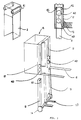
- Fig. 3 illustrates in more detail the roller system which guide the telescoping foot into the telescoping head corresponding.
- Fig. 4 illustrates in more detail a means of adjusting the pebbles located at the upper end of the feet of telescoping.
- Fig. 7 illustrates an anti-dislocation system provided for the end of the teeth.
- Fig. 8 illustrates a variant of the system of FIG. 7.
- Fig. 9 illustrates another security system associated with the frame.
- Fig. 10 illustrates a system for lowering the rollers of the fork.
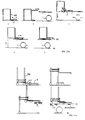
- Fig. 11 schematically shows the loading operation and unloading using a forklift according prior art, compared to a self-loading cart the invention.
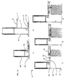
- Fig. 13 illustrates the self-loading operation with wheel motor
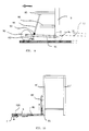
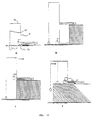
- Fig. 16 illustrates self-loading in the case of a machine with stabilizing foot facing inward frame.
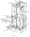
- a forklift 1 having two crutches 2 and 3 (hidden) provided at the front and rear of a chassis 4.
- the two crutches 2 and 3 are retracted in the crutch heads 8 ', 9' and 10 ', 11' respectively.
- a protruding element 5, in the form a fork is integral with the rest of the chassis 4 and located at its base.
- the fork is however interchangeable with other forks by fixing on an element provided for this effect.
- Element 5 (fork) is composed of two teeth 6 provided at their ends with rollers 7 projecting from the underside.
- the two telescopic crutches 2 and 3 are composed each of two telescopic legs 8.9 and 10.11 respectively, which are housed in crutch heads 8 ', 9', 10 ', 11' forming part of the chassis.
- Each foot of crutch is provided at its point of support on the ground with a wheel 13, 14, 15, 16, the rear wheels 14, 15 being, in this example, pivoting.
- the trolley is also fitted with stabilizing feet 12 integral with the front stand which in this example are facing forward and located between the teeth of the fork 5.
- the stabilizing feet are also fitted with castors 19, possibly pivoting.
- the chassis lifting system is also illustrated by compared to the front stand 2.
- This system includes a winch 50 fixed on an upper crosspiece connecting the heads of the front stand and a chain 51 returned by a toothed wheel located on a cross of the stand anterior.
- a crank 52 is provided projecting towards the rear as well as a locking handle 53.
- the vertical movement of the rear stand takes place passively, either due to the weight of the chassis in the case of its re-entry in the corresponding head, either under the effect of its own weight when descending the crutch.
- the chassis beams can advantageously be telescopic in 70 so that you can do vary the length of the assembly. As already mentioned, this execution mode allows the presence of a bumper in protruding from the loading platform of a truck.
- a brake is also illustrated.
- the telescoping foot includes a second pair of rollers 41, in the form of rollers, at its end superior.
- the raceways are two sides opposite interior of the U-shaped profile constituting the head 8 'telescoping.
- the distance between the pairs of rollers is minimal.
- the two pairs are as far apart as possible, which advantageously reduces the play and allows the fork tines to remain parallel to the stabilization feet which must reach the same level to allow the chassis to move forward on the second level.
- Fig. 4 illustrates a detail of embodiment by a view side A and a top view B of the set of rollers 41.
- the distance between the rollers 41 fixed at the end upper of the profiles constituting the legs 8 and 9 of the front stand can be adjusted with a nut 61 acting via a rod 62 on an internal axis 65, parallel to the axis of the rollers, on which two pairs of connecting rods 63, 64 whose outer ends pivot each on an axis 66 coaxial and integral with the axis of rollers 41.
- the angle between the connecting rods, and consequently the distance between the axes of the rollers can thus be adjusted.
- Fig. 5 illustrates in more detail an embodiment for mounting part of the teeth to form the fork secured to the chassis and on the other hand to the feet stabilizers secured to the front stand.
- a fixing pin 174 which can be example pressed at the same time into a hole 175 in the tooth 6 and in one of the holes 176 provided in the crosspiece upper 172, aligned with hole 175 when the tooth 6 is in the chosen position.
- the feet stabilizers 12 of the front stand 2 can be arranged according to the representation at the bottom of FIG. 5.
- the front stand 2 includes a cross horizontal 180 of rectangular hollow section, cross member connecting the two stands 8 and 9. Two parallel faces of this horizontal cross are laid horizontally and have a width greater than the dimension, taken in the same direction, of the heads of crutches. After attaching the stands to the cross 180 so that their longitudinal axes intersect that of said horizontal cross 180, it retains on its upper face 181 two free longitudinal edges 182.
- the horizontal cross-member 180 can extend in overhang outside the legs of crutches 8 and 9.
- a spindle 187 can be inserted into a hole 188 horizontal of a claw 185 at the same time as in one of the horizontal holes 189 which can be aligned with hole 188 and which are provided in the face corresponding vertical of the cross member 180.
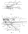
- Fig. 6 illustrates a system of lowering and raising the rollers provided at the free end of the teeth.
- the support rollers 7 of each tooth 6 of the fork can each include means, such as a double arm 120 supporting the caster shaft, on both sides of it.
- the double arm 1.20 can be arranged to move substantially vertically this fulcrum 129 of the roulette 7 so that it can occupy different positions, for example by pivoting around a horizontal shaft 122 which is fixed in tooth 6 formed by a horizontal tube 132, the underside 133 of which has been hollowed out.
- first extreme low position the support points 129 are drowned for the most part in the thickness of the free end, while being able to roll.
- second extreme high position the support points 129 make projection from the underside 133 of this free end.
- a hydraulic cylinder system or other keeps each roller 7 in position desired.
- the first extreme position mentioned above is arranged and used to be able to introduce the fork tine 6 into a usual palette.
- the second extreme position mentioned above is used for example when bringing with the machine a pallet loaded on the upper shelf and the roller 7 must keep the pallet away from the table during the stages of ascent and translation of the machine on the platform to allow easy movement of the machine and the palette during these steps.
- Fig. 7 illustrates a system for blocking the rollers when the ends of the teeth 6 of the fork, when the carriage removal operation after self-unloading, approach the edge of the upper level beyond a certain limit.
- the load and the fork are supported on the roller (s) 7 rolling on the upper level and located at the end of an arm 120 capable of lowering or lift the roller by pivoting around the shaft 122 (see also fig. 6).
- Immobilization can also be done by introducing a lug in a ratchet wheel coaxial with the roller shaft and juxtaposed to it.
- the chassis of the machine according to the invention incorporates the fork facilitates integration of a system. lifting based on the descent of the rollers located at the end of the forks.
- the forks are independent and slide in slides and must therefore contain the means of descent of the rollers.
- all lifting means can be incorporated at the level of the frame.
- Fig. 11 schematically illustrates the different stages of the self-loading operation on the platform of a truck for a forklift following two achievements of the prior art on the one hand (steps 1 to 5 of fig. 11a, principle of document WO83 / 04226 Lutz or US 5,217,342; and FR 1.506.606, fig. 11 b), and following the invention on the other hand (steps 1 'to 5' fig. 11C).
- the platform is at an N2 level relative to the level N1 from the ground.
- the fork of the prior art moves on a fixed mast 200 relative to the frame or chassis (steps 1-2), to rise to a height slightly greater than that of the higher level N2.
- the fork is then engaged above this level by advancing the carriage then the fork, fitted at its end with rolling means, is lowered to support the upper level N2.
- the frame is then raised and the rear stand lowered into the same step 3.
- the rear stand is raised in 5 from level N1 to level N2 and the carriage can move on this higher level, the autoloading being finished.
- the forks is directly connected with the support of the rear stand.
- the fork mast connections guide and fork and rear stand are not very rigid.
- the motorization of the lifting system of the rear stand does not allow the passage of the machine lower level O to a low level x.
- the machine cannot be transferred to each of the intermediate levels between the maximum level authorized this which is not the case for the machine according to the invention.
- Fig. 12 illustrates a pallet picking operation 69 at the quay.
- the chassis is brought up (first load lifting means).
- first load lifting means To be able to introduce fork 6 completely under pallet 69, there is first bring the stabilizing foot 12 up to the fork 6 (step c) which allows the advancement of the machine towards the platform.
- the roller descent mechanism 7 (step e, second lifting means) concomitant with a descent with the same amplitude of the rear stand (3rd lifting means) allows lifting the pallet 69.
- the machine can then self-charge as illustrated previously or can go back for the descent of the front stand, then of the chassis with the fork loaded with the pallet.
- Fig. 14 very schematically shows a machine for transporting long loads placed on a support provided laterally to the chassis.
- Fig. 16 illustrates an embodiment in which it stabilization feet 12 are provided towards the rear, ie towards the chassis. This case may arise when the center of gravity is between the means of rolling of the two crutches.
Landscapes
- Engineering & Computer Science (AREA)
- Transportation (AREA)
- Structural Engineering (AREA)
- Civil Engineering (AREA)
- Life Sciences & Earth Sciences (AREA)
- Geology (AREA)
- Mechanical Engineering (AREA)
- Forklifts And Lifting Vehicles (AREA)
- Crystals, And After-Treatments Of Crystals (AREA)
- Input Circuits Of Receivers And Coupling Of Receivers And Audio Equipment (AREA)
- Control Of Motors That Do Not Use Commutators (AREA)
- Treatment Of Sludge (AREA)
- Vehicle Body Suspensions (AREA)
- Glass Compositions (AREA)
- Loading Or Unloading Of Vehicles (AREA)
- Vehicle Cleaning, Maintenance, Repair, Refitting, And Outriggers (AREA)
- Handcart (AREA)
Claims (16)
- Verladevorrichtung für Lasten oder Zubehöre, die aus einem steifen Formrahmen, der mit mehreren Stützenköpfen versehen ist, und aus mindestens einem Bestandteil der Lasten - oder Werkzeugstütze gesetzt ist. Diese Verladevorrichtung ist wie folgendermassen charakterisiert. Mindestens :ist der steife Rahmen aus einem Obenrahmen ( 4 ) gesetzt, der mit mindestens zwei Stützenköpfen versehen ist, aus denen ein Vorderkopf( 8, 9' ) und ein Hinterkopf( 10', 11' );ist / sind der oder die Bestandteil( e ) der Lasten - oder der Werkzeugstütze im oben erwähnten Formrahmen ( 4 ) eingefügt oder kräftig an ihn befestigt;strecken sich nach unten Stützen ( 2, 3 ) aus, die an die oben erwähnten Stützenköpfen befestigt sind und die mindestens von den oben envähnten Stützenköpfen teilweise gleiten können. Die Gesamtheit von ihren unteren Endungen ist mit mindestens drei Laufmitteln ( 13, 14, 15, 16 ) versehen, die auf eine horizontale Ebene stützen können;springt ein Bestandteil ( 5 ) des oben erwähnten Rahmens ( 4 ) oder ein an den oben envähnten Rahmen ( 4 ) kräftig befestigter Bestandteil im Verhältnis zu der durch den Abwurf der Stützpunkte der Stützen bestimmte Fläche hervor. Dieser vorspringende Bestandteil ( 5 ) ist mit mindestens einem Laufmittel ( 7 ) versehen, das ein Stützpunkt bildet und der so gesetzt ist, um auf eine Ebene stützen zu können, die leicht unter der extremen höher gelegenen Ebene der vorhergehenden Stütze ( 2 ) ;befindet sich der Abwurf des Schwerpunkts der Vorrichtung in der Fläche, die durch den Abwurf von dem oder von den Stützpunkt( en ) ( 7 ) von dem vorspringenden Bestandteil und von dem oder von den Stützpunkt( en ) ( 14, 15 ) der hinteren Stütze ( 3 ) bestimmt ist, das heisst die Stütze, die diesem vorspringenden Bestandteil im Verhältnis zu dem oben erwähnten Rahmen ( 4 ) gegenübergestellt ist;sind Hebe- ( 50, 51, 52 ) sowie Blockierenvorrichtungen vorausgesehen, um die vorhergehende Stütze ( 2 ) herabzusetzen und um einerseits die vorhergehende Stütze und anderseits die hinteren Stütze ( 3 ) unabhängig wiederzuheben und zu blockieren, in Anbetracht, dass diese hintere Stütze im Verhältnis zu dem vorspringendem Bestandteil ( 5 ) am weitesten ist.
- Vorrichtung, die der Rückforderung 1 entspricht, in der der Bestandteil der Lasten stütze ist oder ist nicht unmittelbar kräftig befestigt an dem vorsprinden Bestandteil ( 5 ) im Verhältnis zu der Fläche, die durch die Stützpunkte der Stützen ( 2, 3 ) bestimmt ist.
- Vorrichtung, die der Rückforderung 2 entspricht, in der der Bestandteil der Lastenstütze die Form von einer Gabel ( 6 ) hat.
- Vorrichtung, die irgendwelcher der vorhergehenden Rückforderungen entspricht, in der mindestens ein stabilisierende Fuss ( 12 ) an der Basis der vorhergehenden Stütze ( 2 ) vorhergesehen ist, der nach aussen oder nach innen ausgerichtet ist und der an seiner Endung mit Laufmittel ( 19) versehen ist, das mit der horizontalen Ebene in Verbindung ist.
- Vorrichtung, die irgendwelcher der vorhergehenden Rückforderungen entspricht, in der ein oder mehrere Fuss( Füsse ) ( 8, 9, 10, 11 ) der vorhergehenden Stütze in die entsprechenden Stützenköpfe dank zwei Laufrollenfolgen ( 40, 41 ) oder entsprechenden Mitteln gleiten, in Anbetracht, dass eine der Laufrollenfolgen ( 40 ) befestigt ist und sich an der Basis der Stützenkopse ( 8', 9', 10', 11' ) befindet und sich die andere Laufrollenfolge ( 41) an der höheren Endung des Fusses ( 8, 9, 10, 11 ) befindet, das alles in Anbetracht, dass der Abstand zwischen den zwei Laufrollenfolgen am kleinsten ist, wenn der Fuss völlig herabgesetzt ist und am grössten ist, wenn der Fuss völlig wiedergehoben ist.
- Vorrichtung, die irgendewelcher der vorhergehenden Rückforderungen entspricht, in der die Stützenfüssc ( 8 bis 11 ) und die Stützenköpfe ( 8' bis 11' ) schiebbare Profileisen, U-förmige Winkeleisen oder leere Rohre mit einem viereckigen oder rechteckigen Schnitt sind
- Vorrichtung, die irgendwelcher der vorhergehenden Rückforderungen entspricht, in der die Laufrollenfolge ( 40 ) des Stützenkopfes aus zwei übereinander liegenden Laufrollen gesetzt ist, deren Durchschnitt etwas geringer als die innere Dimension der Stützen ist, die im Verhältnis mit der mittleren vertikalen Achse einerseits und anderseits ein wenig verschoben sind, so dass durch die Handlung des Spiels die Laufwege auf dem Fuss der beweglichen Stütze sich auf den zwei inneren gegenübergestellten Seiten von dieser Stütze befinden.
- Vorrichtung, die irgendwelcher der vorhergehenden Rückforderungen entspricht, in der ein oder mehrere zusätzlichen Laufmittel ( 111 ) vorausgesehen sind: sie sind kräftig am Rahmen befestigt, ein wenig vor den hinteren Stützen und so eingerichtet, dass sie auf eine Ebene stützen können, die ein wenig unter der extremen unteren Ebene der hinteren Stützen ist, wenn diese hinteren Stützen völlig in ihre schiebbaren Köpfe eingetreten sind.
- Vorrichtung, die irgendwelcher der vorhergehenden Rückforderungen entspricht, in der mindestens ein der Laufmittel ein drehbares Rad ( 14, 15 ) ist.
- Vorrichtung, die irgendwelcher der vorhergehenden Rückforderungen entspncht, in der der steife Rahmen ( 4 ) durch Regulierung von horizontal schiebbaren Bestandteilen ( 70 ) horizontal dehnbar ist.
- Vorrichtung, die irgendwelcher der vorhergehenden Rückforderungen entspricht, in der die Herabsetzen - und Hebevorrichtung der Füsse aus mindestens einer Winde mit doppelter Wirkung ( 60 ) oder aus einer Kettenhaspel ( 50 ) gesetzt ist.
- Vorrichtung, die der vorhergehenden Rückforderung 1 entspricht, in der ein Blockiersystem des Laufmittels ( 7 ) des vorspringenden Bestandteils ( 6 ) vorausgesehen ist, wenn die hintere Stütze in der herabgesetzten Lage und die vorliegende Stütze ( 2 ) in der gehobenen Lage ist und wenn das Laufmittel ( 7 ) von diesem vorspringenden Bestandteil ( 6 ) auf einer höheren Ebene ist und sich unter einer vorbestimmten Grenze von seinem Rand nähert.
- Vorrichtung, die irgendwelcher der vorhergehenden Rückforderungen entspncht, in der Mittel vorausgesehen sind, um das Laufmittel des vorspringenden Bestandteils herabzusetzen, damit man so eine Stapelplatte heben kann.
- Vorrichtung, die der vorhergehenden Rückforderung entspricht, die auch aus einer zusätzlichen Hebevorrichtung gesetzt ist, um die hintere Stütze zur gleichen Zeit zum vorspringenden Laufmittel herabzusetzen.
- Vorrichtung, die irgendwelcher der vorhergehenden Vorrichtungen entspricht, in der die Stützen schiebbar sind.
- Vorrichtung, die irgendwelcher der vorhergehenden Vorrichtungen entspricht, in der die Stützenfüsse der envähnten Stützen gleiten innerhalb oder ausserhalb der Stützenköpfe.
Applications Claiming Priority (3)
| Application Number | Priority Date | Filing Date | Title |
|---|---|---|---|
| BE9500128 | 1995-02-16 | ||
| BE9500128A BE1009110A4 (fr) | 1995-02-16 | 1995-02-16 | Chariot porte-charge. |
| PCT/BE1996/000014 WO1996026153A2 (fr) | 1995-02-16 | 1996-02-16 | Chariot porte-charge |
Publications (2)
| Publication Number | Publication Date |
|---|---|
| EP0809600A2 EP0809600A2 (de) | 1997-12-03 |
| EP0809600B1 true EP0809600B1 (de) | 1999-11-24 |
Family
ID=3888786
Family Applications (1)
| Application Number | Title | Priority Date | Filing Date |
|---|---|---|---|
| EP96903841A Expired - Lifetime EP0809600B1 (de) | 1995-02-16 | 1996-02-16 | Lastaufnahme-fahrzeug |
Country Status (7)
| Country | Link |
|---|---|
| EP (1) | EP0809600B1 (de) |
| AT (1) | ATE186899T1 (de) |
| AU (1) | AU4780196A (de) |
| BE (1) | BE1009110A4 (de) |
| DE (1) | DE69605284T2 (de) |
| ES (1) | ES2142048T3 (de) |
| WO (1) | WO1996026153A2 (de) |
Cited By (1)
| Publication number | Priority date | Publication date | Assignee | Title |
|---|---|---|---|---|
| WO2015089640A1 (en) * | 2013-12-19 | 2015-06-25 | Volodymyr Ivanchenko | Apparatus for transporting a load |
Families Citing this family (3)
| Publication number | Priority date | Publication date | Assignee | Title |
|---|---|---|---|---|
| FR2765565B1 (fr) * | 1997-07-04 | 1999-08-20 | Armtop | Elevateur a fourche |
| DE19849769B4 (de) * | 1998-10-28 | 2008-01-17 | Linde Material Handling Gmbh | Rahmen für einen Gabelstapler |
| EP4570736A1 (de) * | 2023-12-14 | 2025-06-18 | Frendix Oy | Hebevorrichtung und verfahren zu deren verwendung |
Family Cites Families (4)
| Publication number | Priority date | Publication date | Assignee | Title |
|---|---|---|---|---|
| FR1506606A (fr) * | 1966-11-10 | 1967-12-22 | Procédé pour faire passer un chariot élévateur d'un premier niveau à un second niveau et chariot équipé pour l'application de ce procédé | |
| WO1982001363A1 (en) * | 1980-10-16 | 1982-04-29 | David W Lutz | Lift and carry truck |
| US4460064A (en) * | 1982-06-03 | 1984-07-17 | Lutz David W | Forklift truck capable of raising and lowering itself and a load back and forth between two surfaces at different levels |
| DE4126728C2 (de) * | 1991-08-13 | 1996-01-18 | Woetzel Karl Heinz | Hebe- und Förderfahrzeug |
-
1995
- 1995-02-16 BE BE9500128A patent/BE1009110A4/fr active
-
1996
- 1996-02-16 AU AU47801/96A patent/AU4780196A/en not_active Abandoned
- 1996-02-16 EP EP96903841A patent/EP0809600B1/de not_active Expired - Lifetime
- 1996-02-16 DE DE69605284T patent/DE69605284T2/de not_active Expired - Fee Related
- 1996-02-16 ES ES96903841T patent/ES2142048T3/es not_active Expired - Lifetime
- 1996-02-16 WO PCT/BE1996/000014 patent/WO1996026153A2/fr not_active Ceased
- 1996-02-16 AT AT96903841T patent/ATE186899T1/de active
Cited By (1)
| Publication number | Priority date | Publication date | Assignee | Title |
|---|---|---|---|---|
| WO2015089640A1 (en) * | 2013-12-19 | 2015-06-25 | Volodymyr Ivanchenko | Apparatus for transporting a load |
Also Published As
| Publication number | Publication date |
|---|---|
| EP0809600A2 (de) | 1997-12-03 |
| ATE186899T1 (de) | 1999-12-15 |
| WO1996026153A2 (fr) | 1996-08-29 |
| BE1009110A4 (fr) | 1996-11-05 |
| DE69605284T2 (de) | 2000-08-03 |
| WO1996026153A3 (fr) | 1996-10-24 |
| ES2142048T3 (es) | 2000-04-01 |
| AU4780196A (en) | 1996-09-11 |
| DE69605284D1 (de) | 1999-12-30 |
Similar Documents
| Publication | Publication Date | Title |
|---|---|---|
| CA1249859A (fr) | Vehicule porte-voitures a structures porteuses transversales individuelles propres a chaque train de roues | |
| EP2819909B1 (de) | Konvertierbare transportvorrichtung deren griff und ràdern gleichzeitig zusammenklappbar sind | |
| EP1476343B1 (de) | Hebevorrichtung sowie sackkarre | |
| FR2687654A1 (fr) | Structure pour permettre de charger ou decharger des marchandises a transporter avec un dispositif de manutention a bras de levage hydraulique. | |
| FR2666553A1 (fr) | Chariot equipe d'une partie de reception de marchandises reliee a un coulisseau mobile en hauteur, et dispositif de guidage pour ce coulisseau. | |
| EP0586318B1 (de) | Umstellbarer, doppelter Boden für Kraftfahrzeuge in einer Transporteinheit | |
| EP0809600B1 (de) | Lastaufnahme-fahrzeug | |
| FR2503644A1 (fr) | Vehicule d'enlevement et de transport des voitures automobiles | |
| EP3028924A1 (de) | Von einem fussgänger gezogener wagen zum passieren von stufen | |
| EP2946994B1 (de) | Anhänger für zweirad-fahrzeug | |
| EP1055558B1 (de) | Ladeplattform | |
| EP0889000A1 (de) | Gabelhubwagen | |
| FR2522597A1 (fr) | Appareil pour la manutention de charges | |
| EP0799789A1 (de) | Vorrichtung zum Befestigen eines Gabelstaplers auf einem Lastkraftwagen, Halterahmen und Lastkraftwagen dafür | |
| FR3067707B1 (fr) | Transpalette | |
| FR2561601A1 (fr) | Chariot de type " diable " pour le transport d'objets tels que des valises | |
| FR2516022A1 (fr) | Chariot a trois roues | |
| FR2836109A1 (fr) | Chariot porte-charge et vehicule d'embarquement d'un tel chariot | |
| FR2724159A1 (fr) | Pont elevateur pour vehicules a prise sous chassis et a prise sous roues | |
| FR2940937A1 (fr) | Dispositif de support destine a faciliter le chargement d'un caisson ou d'un plateau sur une plate-forme | |
| EP0749921B1 (de) | Rollgestell zum Transportieren, Lagern, Handhaben und Einbauen von vertikalen und flachen Elementen | |
| FR2918322A1 (fr) | Betaillere comprenant au moins un plancher mobile | |
| FR2600994A1 (fr) | Portique pour chariots elevateurs | |
| FR2731250A1 (fr) | Ensemble avec nacelle et plate-forme de travail en hauteur, a entrainement multi-directionnel | |
| FR2794448A1 (fr) | Dispositif auxiliaire d'embarquement d'un chariot sur un camion |
Legal Events
| Date | Code | Title | Description |
|---|---|---|---|
| PUAI | Public reference made under article 153(3) epc to a published international application that has entered the european phase |
Free format text: ORIGINAL CODE: 0009012 |
|
| 17P | Request for examination filed |
Effective date: 19970912 |
|
| AK | Designated contracting states |
Kind code of ref document: A2 Designated state(s): AT DE ES FR GB GR IT NL |
|
| GRAG | Despatch of communication of intention to grant |
Free format text: ORIGINAL CODE: EPIDOS AGRA |
|
| 17Q | First examination report despatched |
Effective date: 19980313 |
|
| GRAG | Despatch of communication of intention to grant |
Free format text: ORIGINAL CODE: EPIDOS AGRA |
|
| GRAH | Despatch of communication of intention to grant a patent |
Free format text: ORIGINAL CODE: EPIDOS IGRA |
|
| GRAH | Despatch of communication of intention to grant a patent |
Free format text: ORIGINAL CODE: EPIDOS IGRA |
|
| GRAA | (expected) grant |
Free format text: ORIGINAL CODE: 0009210 |
|
| AK | Designated contracting states |
Kind code of ref document: B1 Designated state(s): AT DE ES FR GB GR IT NL |
|
| PG25 | Lapsed in a contracting state [announced via postgrant information from national office to epo] |
Ref country code: NL Free format text: LAPSE BECAUSE OF FAILURE TO SUBMIT A TRANSLATION OF THE DESCRIPTION OR TO PAY THE FEE WITHIN THE PRESCRIBED TIME-LIMIT Effective date: 19991124 Ref country code: GR Free format text: LAPSE BECAUSE OF NON-PAYMENT OF DUE FEES Effective date: 19991124 Ref country code: AT Free format text: LAPSE BECAUSE OF FAILURE TO SUBMIT A TRANSLATION OF THE DESCRIPTION OR TO PAY THE FEE WITHIN THE PRESCRIBED TIME-LIMIT Effective date: 19991124 |
|
| REF | Corresponds to: |
Ref document number: 186899 Country of ref document: AT Date of ref document: 19991215 Kind code of ref document: T |
|
| REF | Corresponds to: |
Ref document number: 69605284 Country of ref document: DE Date of ref document: 19991230 |
|
| ITF | It: translation for a ep patent filed | ||
| GBT | Gb: translation of ep patent filed (gb section 77(6)(a)/1977) |
Effective date: 20000221 |
|
| REG | Reference to a national code |
Ref country code: ES Ref legal event code: FG2A Ref document number: 2142048 Country of ref document: ES Kind code of ref document: T3 |
|
| NLV1 | Nl: lapsed or annulled due to failure to fulfill the requirements of art. 29p and 29m of the patents act | ||
| PLBE | No opposition filed within time limit |
Free format text: ORIGINAL CODE: 0009261 |
|
| STAA | Information on the status of an ep patent application or granted ep patent |
Free format text: STATUS: NO OPPOSITION FILED WITHIN TIME LIMIT |
|
| 26N | No opposition filed | ||
| PG25 | Lapsed in a contracting state [announced via postgrant information from national office to epo] |
Ref country code: DE Free format text: LAPSE BECAUSE OF NON-PAYMENT OF DUE FEES Effective date: 20010103 |
|
| PGFP | Annual fee paid to national office [announced via postgrant information from national office to epo] |
Ref country code: FR Payment date: 20010226 Year of fee payment: 6 |
|
| REG | Reference to a national code |
Ref country code: GB Ref legal event code: IF02 |
|
| PGFP | Annual fee paid to national office [announced via postgrant information from national office to epo] |
Ref country code: GB Payment date: 20020215 Year of fee payment: 7 |
|
| PGFP | Annual fee paid to national office [announced via postgrant information from national office to epo] |
Ref country code: ES Payment date: 20020226 Year of fee payment: 7 |
|
| PG25 | Lapsed in a contracting state [announced via postgrant information from national office to epo] |
Ref country code: GB Free format text: LAPSE BECAUSE OF NON-PAYMENT OF DUE FEES Effective date: 20030216 |
|
| PG25 | Lapsed in a contracting state [announced via postgrant information from national office to epo] |
Ref country code: ES Free format text: LAPSE BECAUSE OF NON-PAYMENT OF DUE FEES Effective date: 20030217 |
|
| GBPC | Gb: european patent ceased through non-payment of renewal fee | ||
| PG25 | Lapsed in a contracting state [announced via postgrant information from national office to epo] |
Ref country code: FR Free format text: LAPSE BECAUSE OF NON-PAYMENT OF DUE FEES Effective date: 20031031 |
|
| REG | Reference to a national code |
Ref country code: FR Ref legal event code: ST |
|
| REG | Reference to a national code |
Ref country code: ES Ref legal event code: FD2A Effective date: 20030217 |
|
| PG25 | Lapsed in a contracting state [announced via postgrant information from national office to epo] |
Ref country code: IT Free format text: LAPSE BECAUSE OF NON-PAYMENT OF DUE FEES;WARNING: LAPSES OF ITALIAN PATENTS WITH EFFECTIVE DATE BEFORE 2007 MAY HAVE OCCURRED AT ANY TIME BEFORE 2007. THE CORRECT EFFECTIVE DATE MAY BE DIFFERENT FROM THE ONE RECORDED. Effective date: 20050216 |
|
| PG25 | Lapsed in a contracting state [announced via postgrant information from national office to epo] |
Ref country code: FR Free format text: LAPSE BECAUSE OF NON-PAYMENT OF DUE FEES Effective date: 20020228 |