EP0809089A2 - Procédé et dispositif pour la mesure électromagnétique de débit - Google Patents
Procédé et dispositif pour la mesure électromagnétique de débit Download PDFInfo
- Publication number
- EP0809089A2 EP0809089A2 EP97107796A EP97107796A EP0809089A2 EP 0809089 A2 EP0809089 A2 EP 0809089A2 EP 97107796 A EP97107796 A EP 97107796A EP 97107796 A EP97107796 A EP 97107796A EP 0809089 A2 EP0809089 A2 EP 0809089A2
- Authority
- EP
- European Patent Office
- Prior art keywords
- magnetic field
- measuring
- magnetic
- coil
- current
- Prior art date
- Legal status (The legal status is an assumption and is not a legal conclusion. Google has not performed a legal analysis and makes no representation as to the accuracy of the status listed.)
- Withdrawn
Links
Images


Classifications
-
- G—PHYSICS
- G01—MEASURING; TESTING
- G01F—MEASURING VOLUME, VOLUME FLOW, MASS FLOW OR LIQUID LEVEL; METERING BY VOLUME
- G01F1/00—Measuring the volume flow or mass flow of fluid or fluent solid material wherein the fluid passes through a meter in a continuous flow
- G01F1/56—Measuring the volume flow or mass flow of fluid or fluent solid material wherein the fluid passes through a meter in a continuous flow by using electric or magnetic effects
- G01F1/58—Measuring the volume flow or mass flow of fluid or fluent solid material wherein the fluid passes through a meter in a continuous flow by using electric or magnetic effects by electromagnetic flowmeters
- G01F1/60—Circuits therefor
Definitions
- the invention relates to a method and a device for measuring the flow rate of a flowable medium according to the preamble of claim 1 and claim 13.
- magnetic field excitation in the form of a clocked or switched (or clocked pole-reversed) direct field and magnetic field excitation in the form of a sinusoidal alternating field.
- the clocked (or clocked polarity reversed) constant field excitation is characterized in that a stable zero point and a stable measuring span of the measuring signal can be achieved. Due to the inevitable inductances and losses in the coil excitation circuit, the respective steady-state value B 0 of the B-field does not occur immediately with the pulsed DC field excitation relative to the excitation current switching times, but only after a rise time has elapsed. This problem has been circumvented so far that the excitation current switching frequency has been chosen so small that the stationary state of the magnetic field B could be set in every cycle time switched on coil current and that the measuring voltage between the measuring electrodes was detected only in the time segments of the stationary magnetic field. The respective rise times in the clock cycles of the switched-on coil current are not used to detect the measuring voltage. The measurement is blanked out there accordingly.
- the magnetic-inductive flow meters previously operated according to the principle of magnetic field excitation with clocked or clocked polarity reversed polarity comparatively sluggish, so that their area of application is essentially limited to standard flow measurement tasks, for example in the water supply and wastewater sector.
- Flow measurements with switched or switched polarity reversed direct field are also used to monitor relatively slow liquid dosing processes.
- magnetic-inductive flow meters according to the principle of magnetic field excitation in the form of a sinusoidal, in particular network-synchronous alternating field has the advantage that the measuring voltage can be measured continuously with a high sampling rate, so that changes in flow rate can be detected comparatively quickly.
- Current areas of application for the operation of magnetic-inductive flow meters with sinusoidal alternating field excitation are, for example, the monitoring of short-term dosing processes, flow measurements of multi-phase measuring materials, paper pulps and fruit mixtures as well as flow measurements in the case of comparatively strongly fluctuating flows, such as occur when operating with piston pumps.
- the present invention relates to the operation of magnetic-inductive flow meters with clocked or clocked polarity reversed DC field excitation.
- the object of the invention is to show ways in which the available measurement information can be used more efficiently in a magnetic-inductive flow meter with clocked or clocked polarity-reversed DC field excitation, in particular higher resolutions or a faster response of the magnetic-inductive To achieve flow meter.
- the time segment for recording measurement information in which the magnetic field has not yet reached its steady state is already used in the respective cycle time intervals when the coil current is switched on.
- the sampling of the measurement voltage in the coil current switched on at the cycle time intervals can be controlled in such a way that several sample values of the measurement voltage are recorded in each cycle time interval.
- the sampled values which are detected during the time periods in which the magnetic field has not yet reached its steady state can be corrected by means of correction factors in order to extrapolate the respective measurement voltage for the case of measurement with a steady magnetic field.
- the measuring voltage with a stationary magnetic field is proportional to the flow rate to be determined to a good approximation.
- a correction factor is assigned to each measurement voltage value recorded in the time range of the (still) non-stationary magnetic field, which depends on the measurement instant of the measurement value within the relevant cycle time interval of the coil current switched on.
- the correction factors can be determined, for example, by calibration measurements or system parameter measurements and kept ready in a memory of an evaluation device.
- the measuring mode explained above allows a comparatively high sampling rate, wherein each cycle time interval of the coil current switched on can be used essentially completely for the recording of measured values.
- the measuring system in question can react relatively quickly to changes in flow, so that applications are opened up which were previously the measuring operation reserved with sinusoidal alternating field excitation.
- Another measuring mode provides that only one voltage measurement value is recorded in each clock time interval of the coil current that is switched on, but the scanning integration time interval (measuring time window) is so large that it preferably covers almost the entire time range of the relevant clock time interval.
- the measurement values in question are normalized or corrected with correction factors, the correction factors depending on the width of the scan integration time interval (measurement time window) and the relative position of the scan integration time interval within the relevant cycle time intervals.
- the cycle time intervals of the switched-on coil current be selected so long that the magnetic field reaches its steady state.
- the coil excitation current is switched with at least two alternating switching frequencies, the cycle time intervals at one of these frequencies being sufficiently long to build up a stationary magnetic field.
- the measuring voltage is recorded in the state of the stationary magnetic field in order to provide calibration values with which the above-mentioned correction factors are checked and, if necessary, can be corrected. If the measured voltage values estimated using the correction factors deviate systematically from the corresponding calibration values over a predetermined time, the correction factors are corrected in order to improve the estimates.
- the corresponding calibration values can be obtained by reducing the scan integration time interval for the measurement value recording in sufficiently long cycle time intervals and only in the time range in which the magnetic field has reached its steady state.
- the method according to claim 9 in which the coil excitation current is switched with at least two different, alternating switching frequencies and the measuring voltage is sampled in a predetermined temporal relationship with the preceding coil excitation current switching instant in the cycle time intervals of the switched-on coil current.
- Another special feature is that the number of periods in the period trains of the alternating switching frequencies is varied in an irregular manner. This aspect is of independent importance in the context of the invention.
- the measuring method according to claim 9 is particularly suitable for use with periodically fluctuating flows, such as can be caused by piston pumps or the like.
- periodically fluctuating flows such as can be caused by piston pumps or the like.
- the delivery circuit of the flowable medium In the delivery circuit of the flowable medium.
- a periodically pulsating flow curve is sampled at a constant frequency (or two periodically alternating fixed frequencies)
- the synchronization of the measured value sampling and the periodic flow change can lead to a beat behavior and thus to a systematic error of preferably an average one Flow rate indicative output signal (a signal averaged over several samples) come from a magnetic-inductive flow meter.
- the number of the respective periods in the alternating period cycles of the different switching frequencies can be selected statistically from a predetermined number range, for example by means of a random number generator.
- a magnetic-inductive flow meter with the features of claim 13 is proposed.
- the flow meter according to the invention allows the sampling integration time intervals of the measured value integrator to be placed in the rise time range of the magnetic field or, if necessary, to be expanded continuously and thus also to utilize the information which the measurement voltage already contains before the steady state of the magnetic field is reached.
- Fig. 1 shows a block diagram of a magnetic-inductive flow meter according to the invention.
- FIG. 2 shows a characteristic in a simplified diagram Time behavior of the measuring voltage and the magnetic field in the cycle time intervals switched on coil current and the possibility of multiple sampling of the measuring voltage in the cycle time interval.
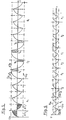
- FIG. 3 shows in an explanatory diagram the course of the measuring voltage with clocked polarity reversed DC field excitation and the possibility of multiple sampling per excitation current cycle time interval.
- FIG. 4 shows in an explanatory diagram the time course of the measuring voltage and the possibility of individual sampling of each clock time interval with a wide sampling integration time interval.
- FIG. 5 shows in an explanatory diagram the course of the measuring voltage when the magnetic field is excited with two alternating excitation frequencies and the possibility of recording calibration values.
- FIG. 6 shows in an explanatory diagram the time course of the measuring voltage with magnetic field excitation with two different, alternating frequencies, the number of periods in the respective period cycles varying irregularly.
- Fig. 1 shows a block diagram of a magnetic-inductive flow meter according to the invention.
- the flow meter has a measuring tube 1, an electromagnetic coil arrangement 2 for generating a magnetic field passing through the measuring tube 1 (induction flux density B) and a pair of measuring electrodes 3, 3 ', which, with the at least to a small extent electrically conductive medium flowing through the measuring tube 1, galvanically into Contact is there.
- the assembly 1, 2, 3, 3 ' is of a conventional type. Due to the flow of the flowable medium which runs transversely to the magnetic field, a measuring voltage is induced which is tapped via the electrodes 3, 3 ' can be.
- the measuring voltage tapped off at the electrodes 3, 3 ' is directly proportional to the flow rate Q of the flowable medium in the pipe 1.
- Magnetic-inductive flowmeters are therefore often operated with a clocked or switched direct field, the driver current J for the coil arrangement being periodically switched on and off or reversed in order to switch the magnetic field on and off accordingly or to reverse its direction.
- the present invention also makes use of the principle of the clocked magnetic field.
- the coil arrangement 2 is connected to a controllable driver circuit 4, which supplies the excitation current I for the coil arrangement 2.
- the driver circuit 4 contains a direct current source 6 for the coil arrangement 2, a controllable reversing pole bridge circuit 8 fed from the direct current source 6 for optionally changing the direction of current flow of the coil current I and a controllable on / off switch 10 for optionally interrupting the coil current I.
- the driver circuit 4 is connected to a control and evaluation device 12 which controls the functions of the pole-reversal bridge circuit 8 and the switching device 10 in a programmed or programmable manner in a microprocessor-controlled manner.
- the control and evaluation device 12 in connection with the driver circuit 4 thus controls the switching on and off of the magnetic field B, the duration of the states: magnetic field switched on or magnetic field switched off and the direction of the magnetic field in the measuring tube 1.
- the flow meter On the measured value acquisition and evaluation side, the flow meter according to FIG. 1 has an input amplifier 14 connected to the measuring electrodes 3, 3 ', a low-pass filter 16 connected downstream of the input amplifier 14 with an optionally programmable cut-off frequency, an analog amplifier 18 connected downstream of the low-pass filter 16, and an analog amplifier 18 downstream measurement value integration stage 20 with adjustable sampling integration time interval, the control and evaluation device 12 and a display unit 22.
- the control and evaluation device 12 controls the adjustable cut-off frequency of the filter 16 and the amplification of the analog amplifier 18.
- the control and evaluation device 12 is also set up to determine the duration of the scan integration time intervals of the measured value integrator 20 and the temporal position of the scan integration time intervals relative to switching events of the driver circuit 4 to control.
- the control and evaluation device 12 receives digitized measurement values from the measurement value integrator 20 via the data line 24.
- An evaluation routine of the control and evaluation device 12 evaluates the digital measurement values of the measurement value integrator 20 to determine flow rate values and indicates the flow rate averaged by means of the display 22 .
- the voltage signal U (t) present at the input of the measured value integrator 20 corresponds to the detection voltage between the measuring electrodes 3, 3 'which is freed of higher-frequency interference by the filter 16 and amplified by the amplifier 18.
- FIG. 2 To further explain the invention, reference is first made to FIG. 2 below.
- Fig. 2 shows qualitatively the temporal behavior of the magnetic field B in the event that the coil current is periodically switched on and off.
- the time profile of the voltage U (t) applied to the measured value integrator 20 corresponds qualitatively the time course of the B field. Due to unavoidable inductances and losses in the coil excitation circuit, the steady-state value B 0 of the B field does not set up without delay relative to the current switch-on times E, but only after a rise time t a has elapsed.
- the detection voltage U (t) applied to the measured value integrator 20 behaves accordingly at a constant flow rate.
- the switch-on clock cycles .DELTA.T have hitherto been selected to be sufficiently long that B and thus U (t) could reach the steady state B 0 or U 0 .
- the measurement voltage was then registered at the end of the clock cycles .DELTA.T switched-on coil current over a sampling integration time interval T int , as is indicated in FIG. 2.
- T int sampling integration time interval
- the invention is based on the idea of obtaining and evaluating measurement information from the detection voltage U (t) in the time range ta in which the steady state of the B field has not yet occurred.
- Trial measurements at a constant flow rate have shown that the stationary magnetic field and correspondingly also the detection voltage U (t) build up with a characteristic time behavior dependent on the magnetic excitation system, which can be determined by calibration or system parameter measurements.
- correction factors k i are thus assigned to the individual measuring points t i , which can be used to remove the steady-state values U 0 sought, which are proportional to the flow rate to be determined to a good approximation to estimate the voltage values U i measured at times t i .
- the control and evaluation device 12 takes over the control of the time sequences of the switching of the coil excitation current and the measurement taking and also the numerical evaluation of the measurement results.
- the control and evaluation device 12 specifies the times t i of the measured values taken by the measured value integrator 20 relative to the switching times of the coil excitation current I and the duration of the respective integration time intervals for taking the measured values U i under program control.
- the flow meter according to the invention according to FIG. 1 allows different measurement modes for the flow rate determination to be carried out on the premise that the available measurement information is better utilized than before. Preferred measurement modes are explained below.
- the control and evaluation device 12 controls the polarity reversal bridge circuit 8 in such a way that the current direction of the coil excitation current I is periodically reversed at a frequency f of, for example, 25 Hz.
- a frequency f of, for example, 25 Hz.
- An exemplary qualitative profile of the voltage U (t) applied to the measured value integrator 20 is shown in FIG. 3. In the case of FIG. 3, the switching frequency of the track excitation current I is so high that the voltage U (t) does not reach the steady state U 0 or -U 0 .
- the measured value integrator 20 scans the voltage U (t) under the control of the control and evaluation device 12 at times t 1 , t 2 .... t n in each half-period ⁇ T and outputs corresponding digitized measured values U 1 , U 2 .. .. U n via the data line 24 to the control and evaluation device 12.
- Correction factors k i are stored in the control and evaluation device 12 and are assigned to the relevant measurement time t i in the manner already described above.
- the measured values U 1 , U 2 .... U n are multiplied by the relevant correction factors k 1 , k 2 .... k n in order to estimate the relevant values U 01 , U 02 .... U 0n .
- control and evaluation device 12 can form an average value from the determined values U 01 ... U 0n .
- control and evaluation device 12 also able 2 ⁇ T estimated value -U 0 to subtract the in each period of the estimated value in the same period + U 0th
- the available measurement information is optimally used without the previous waiting times of conventional flow measurement systems with a switched DC field. Since the steady state of the magnetic field does not have to be waited for after switching the coil current, it is possible to work with a correspondingly higher current switching frequency, which enables a faster reaction of the flow meter according to the invention to changes in flow. In this case, relatively precise measurement results are obtained if the flow rate is essentially constant over at least one period 2 ⁇ T.
- the correction factors k i can be determined empirically by means of calibration measurements and depend on the respective response function of the excitation system for the magnetic field when the coil current is switched on and off or switched over.
- measuring mode 1 can also be operated at a lower current switching frequency, so that the stationary state of magnetic field B and measuring voltage U can be established in each half-period ⁇ T.
- the available measurement information is nevertheless better utilized, since evaluable measurement results are obtained even during the inevitable rise time of the magnetic field B.
- the measured values U 0 recorded after the steady state has been reached can be used by the control and evaluation device 12 to check the correction values k i and, if necessary, to correct or update them, for example to take account of changes in the correction values k i due to temperature changes .
- the measured values U i recorded in accordance with measurement mode 1 can also be evaluated in the alternative manner explained below in order to obtain results on the flow rate.
- the control and evaluation device carries out a curve adaptation by means of the compensation calculation using the method of the least squares using the measured values U i .
- U (t) U 0 (1-e -t / ⁇ )
- U 0 U 0 (1-e -t / ⁇ )
- the second measuring mode explained with reference to FIG. 4 does not differ in terms of the timing of the magnetic field B from the first measuring mode explained with reference to FIG. 3.
- the voltage curve U (t) is not sampled with several measured values per half-period ⁇ T, but one measured value U is recorded for each half-period ⁇ T, although a very wide sampling integration time interval T int is selected for the integration of the relevant measured values . Since the sampling integration time interval T int (also) extends over a range of the rise time ta in which the voltage U has not yet reached the stationary value U 0 , the relevant measured values U are to be corrected with a correction factor in order to estimate the value U 0 .
- the correction factor k in question depends on the width of the sampling integration time interval T int and on the relative position of the sampling integration time interval T int within the relevant half-period ⁇ T and can be determined empirically by means of a calibration measurement. Corresponding correction factors are kept in a memory of the control and evaluation device 12.
- the available measurement information is optimally used, avoiding waiting times.
- the stationary measurement voltage values U 0 determined in this way can be used to correct or update the above-mentioned correction factors k in order to take into account any changes in the correction factors, for example due to changes in the temperature.
- the measured value acquisition by means of the measured value integrator 20 can take place during the phases of higher frequency in the manner described with reference to the first measurement mode or in the manner described with reference to the second measurement mode.
- a voltage measurement value is recorded exclusively in the stationary range (cf. sampling integration time interval T x ). If these control values of the steady-state voltage U 0 and the corresponding estimated values U 0 are constant but systematically unequal over a longer period of time, the measured control values U 0 are used to check the correction values k i or k, which are used for the estimation in the manner described above the U 0 values from the measurements with the higher current switching frequency f 1 are used.
- the measuring span and the zero point of the measurements can be checked and corrected if necessary.
- the fourth measuring mode explained with reference to FIG. 6 is also operated with at least two current switching frequencies f 1 , f 2 of the excitation current I which alternate over time.
- the frequencies f 1 and f 2 do not have any common harmonics.
- the higher frequency f 1 can be chosen so that stationary states of the magnetic field B can occur in the associated half-periods.
- a special feature of measuring mode No. 4 is that the cycles of shorter periods (f 1 ) and longer periods (f 2 ) do not alternate periodically.
- the number of excitation cycles of both frequencies is stochastically determined by means of a random number generator of the control and evaluation device 12, the maximum number of successive cycles of the same frequency being adjustable adjustable.
- the measurement value acquisition and evaluation can be carried out in the fourth measurement mode in one of the ways described above or, if appropriate, also by exclusive measurement value acquisition in the respective stationary areas.
- Magnetic field excitation in accordance with the fourth measuring mode has particular advantages when measuring flows which have periodic flow fluctuations, such as can be caused by piston pumps or the like in the delivery circuit of the flowable medium.
- the synchronization of measured value acquisition and periodic flow change can lead to a beat behavior and thus to a systematic error in the output signal, which preferably indicates an average flow rate of a magnetic-inductive flow meter.
- the magnetic-inductive flow meter according to the invention operated according to the fourth measuring mode outputs a result which correctly reflects the mean flow rate in the case of periodically fluctuating flows.
Priority Applications (1)
| Application Number | Priority Date | Filing Date | Title |
|---|---|---|---|
| EP06005303A EP1672330A3 (fr) | 1996-05-24 | 1997-05-13 | Procédé et dispositif pour la mesure électromagnétique de débit |
Applications Claiming Priority (3)
| Application Number | Priority Date | Filing Date | Title |
|---|---|---|---|
| DE19621132 | 1996-05-24 | ||
| DE19621132A DE19621132A1 (de) | 1996-05-24 | 1996-05-24 | Verfahren und Vorrichtung zur magnetisch-induktiven Durchflußmessung |
| US08/862,780 US5905206A (en) | 1996-05-24 | 1997-05-23 | Method and apparatus for magneto-inductive flow measurement |
Related Child Applications (1)
| Application Number | Title | Priority Date | Filing Date |
|---|---|---|---|
| EP06005303A Division EP1672330A3 (fr) | 1996-05-24 | 1997-05-13 | Procédé et dispositif pour la mesure électromagnétique de débit |
Publications (2)
| Publication Number | Publication Date |
|---|---|
| EP0809089A2 true EP0809089A2 (fr) | 1997-11-26 |
| EP0809089A3 EP0809089A3 (fr) | 1998-07-22 |
Family
ID=26026037
Family Applications (1)
| Application Number | Title | Priority Date | Filing Date |
|---|---|---|---|
| EP97107796A Withdrawn EP0809089A3 (fr) | 1996-05-24 | 1997-05-13 | Procédé et dispositif pour la mesure électromagnétique de débit |
Country Status (3)
| Country | Link |
|---|---|
| US (1) | US5905206A (fr) |
| EP (1) | EP0809089A3 (fr) |
| DE (1) | DE19621132A1 (fr) |
Cited By (6)
| Publication number | Priority date | Publication date | Assignee | Title |
|---|---|---|---|---|
| DE10214323C1 (de) * | 2002-03-28 | 2003-08-28 | Krohne Messtechnik Kg | Magnetisch-induktives Durchflußmeßverfahren |
| US6820499B2 (en) | 2002-05-14 | 2004-11-23 | Krohne Messtechnik Gmbh & Co. K.G. | Method for determining the uncertainty factor of a measuring procedure employing a measuring frequency |
| DE10345297A1 (de) * | 2003-09-30 | 2005-05-04 | Abb Patent Gmbh | Verfahren zum Betrieb einer induktiven Durchflussmesseinrichtung |
| CZ302552B6 (cs) * | 1999-08-16 | 2011-07-13 | Krohne Messtechnik Gmbh | Magneticko-indukcní zpusob merení prutoku proudících médií |
| WO2018215034A1 (fr) * | 2017-07-07 | 2018-11-29 | Apator Miitors Aps | Débitmètre électromagnétique |
| WO2020001876A1 (fr) * | 2018-06-28 | 2020-01-02 | Endress+Hauser Flowtec Ag | Procédé de mise en œuvre d'un débitmètre magnéto-inductif et débitmètre magnéto-inductif |
Families Citing this family (24)
| Publication number | Priority date | Publication date | Assignee | Title |
|---|---|---|---|---|
| US8467986B2 (en) | 1997-11-26 | 2013-06-18 | Invensys Systems, Inc. | Drive techniques for a digital flowmeter |
| US8447534B2 (en) | 1997-11-26 | 2013-05-21 | Invensys Systems, Inc. | Digital flowmeter |
| US7784360B2 (en) | 1999-11-22 | 2010-08-31 | Invensys Systems, Inc. | Correcting for two-phase flow in a digital flowmeter |
| US20030216874A1 (en) | 2002-03-29 | 2003-11-20 | Henry Manus P. | Drive techniques for a digital flowmeter |
| EP1202031A1 (fr) * | 2000-10-24 | 2002-05-02 | Endress + Hauser Flowtec AG | Procédé et appareil pour le contrôle de processus avec un capteur par induction magnétique |
| DE10060706A1 (de) * | 2000-12-07 | 2002-06-13 | Flowtec Ag | Verfahren und eine Vorrichtung zur System- und/oder Prozeßüberwachung |
| DE10134672C1 (de) * | 2001-07-20 | 2003-01-09 | Krohne Messtechnik Kg | Magnetisch-induktives Durchflußmeßgerät |
| US20050226067A1 (en) * | 2002-12-19 | 2005-10-13 | Matrix Semiconductor, Inc. | Nonvolatile memory cell operating by increasing order in polycrystalline semiconductor material |
| DE102005033290B4 (de) * | 2005-07-16 | 2013-11-28 | Abb Ag | Verfahren und Einrichtung zur Erkennung von physikalisch-chemischen Zuständen an Messelektroden eines Durchflussmessers |
| US9182258B2 (en) | 2011-06-28 | 2015-11-10 | Rosemount Inc. | Variable frequency magnetic flowmeter |
| AR093417A1 (es) * | 2012-11-14 | 2015-06-03 | Krohne Ag | Dispositivo de medicion de flujo por resonancia magnetica nuclear y procedimiento para operar un dispositivo de medicion de flujo por resonancia magnetica nuclear |
| DE102014007426B4 (de) * | 2013-07-01 | 2022-07-07 | Krohne Messtechnik Gmbh | Magnetisch-induktives Durchflussmessgerät und Verfahren zum Betreiben eines magnetisch-induktiven Durchflussmessgeräts |
| KR20170037260A (ko) * | 2015-09-25 | 2017-04-04 | 현대자동차주식회사 | 차량용 배터리 시스템 및 그 제어 방법 |
| DE102015120103B4 (de) * | 2015-11-19 | 2018-09-13 | Krohne Ag | Verfahren zur Durchflussmessung durch ein magnetisch-induktives Durchflussmessgerät |
| DE102016124977B4 (de) * | 2016-12-20 | 2021-12-16 | Endress+Hauser Flowtec Ag | Verfahren zum Betreiben eines magnetisch-induktiven Durchflussmessgeräts und ein solches Durchflussmessgerät |
| DE102016124976A1 (de) | 2016-12-20 | 2018-06-21 | Endress+Hauser Flowtec Ag | Verfahren zum Betreiben eines magnetisch-induktiven Durchflussmessgeräts und ein solches Durchflussmessgerät |
| US11204268B2 (en) | 2019-09-05 | 2021-12-21 | Micro Motion, Inc. | Magnetic flowmeter having a programmable bi-directional current generator |
| US11181404B2 (en) | 2019-09-05 | 2021-11-23 | Micro Motion, Inc. | Magnetic flowmeter with a current sampling circuit sampling coil current pulses at a sampling frequency |
| US11333537B2 (en) | 2019-09-05 | 2022-05-17 | Micro Motion, Inc. | Load leveling boost supply for magnetic flowmeter |
| US11204267B2 (en) | 2019-09-05 | 2021-12-21 | Micro Motion, Inc. | Continuously adaptive digital coil driver for magnetic flowmeter |
| US11156486B2 (en) | 2019-09-13 | 2021-10-26 | Micro Motion, Inc. | Magnetic flowmeter with improved processing |
| US11092470B2 (en) | 2019-09-13 | 2021-08-17 | Micro Motion Inc. | Magnetic flowmeter with noise adaptive dead time |
| US11060893B2 (en) * | 2019-09-13 | 2021-07-13 | Micro Motion Inc. | Magnetic flowmeter with flow independent autozero estimation |
| DE102019126883A1 (de) * | 2019-10-07 | 2021-04-08 | Endress+Hauser Flowtec Ag | Verfahren zum Überwachen eines Meßgeräte-Systems |
Citations (5)
| Publication number | Priority date | Publication date | Assignee | Title |
|---|---|---|---|---|
| US4117721A (en) * | 1977-09-21 | 1978-10-03 | Hokushin Electric Works, Ltd. | Magnetic flowmeter |
| GB2186373A (en) * | 1986-02-06 | 1987-08-12 | Danfoss As | Electromagnetic flowmeters and flowmetering methods |
| GB2271639A (en) * | 1992-10-15 | 1994-04-20 | Abb Kent Taylor Ltd | Eliminating periodic interference from measurement signals |
| EP0629843A1 (fr) * | 1993-06-21 | 1994-12-21 | Kabushiki Kaisha Toshiba | Débitmètre électromagnétique et méthode de mesure correspondante |
| DE4423169A1 (de) * | 1994-07-04 | 1996-01-11 | Krohne Ag | Verfahren zur Messung des Durchflusses eines strömenden Mediums |
Family Cites Families (9)
| Publication number | Priority date | Publication date | Assignee | Title |
|---|---|---|---|---|
| US4159645A (en) * | 1977-11-11 | 1979-07-03 | Monitek, Inc. | Electromagnetic fluid flow meter with tolerance to spurious signals |
| US4262543A (en) * | 1979-10-09 | 1981-04-21 | Emerson Electric Co. | Magnetic flowmeter having multiple stage amplifier with automatic zeroing |
| US4370892A (en) * | 1980-07-10 | 1983-02-01 | Fischer & Porter Co. | Electromagnetic flowmeter having noise suppression network |
| DE3132471C2 (de) * | 1980-10-02 | 1984-11-29 | Flowtec AG, Reinach, Basel | Verfahren und Anordnung zur Kompensation der Störgleichspannungen im Elektrodenkreis bei der magnetisch-induktiven Durchflußmessung |
| FR2589571B1 (fr) * | 1985-10-31 | 1990-02-09 | Sereg Soc | Debitmetre electromagnetique a champ magnetique pulse |
| US4704907A (en) * | 1986-07-11 | 1987-11-10 | Fischer & Porter Company | Electromagnetic flowmeter with triangular flux drive |
| DE3829564C2 (de) * | 1988-08-31 | 1999-02-04 | Fischer & Porter Gmbh | Verfahren zur Erzeugung eines der Stromstärke eines fließenden, elektrisch leitenden Mediums entsprechenden Signals bei einem elektromagnetischen Durchflußmesser |
| DE59106056D1 (de) * | 1991-11-22 | 1995-08-24 | Fischer & Porter Gmbh | Schaltungsanordnung für eine Vorrichtung zur Messung der Stärke des Stroms einer elektrische Ladungen enthaltenden Flüssigkeit. |
| US5325728A (en) * | 1993-06-22 | 1994-07-05 | Medtronic, Inc. | Electromagnetic flow meter |
-
1996
- 1996-05-24 DE DE19621132A patent/DE19621132A1/de not_active Withdrawn
-
1997
- 1997-05-13 EP EP97107796A patent/EP0809089A3/fr not_active Withdrawn
- 1997-05-23 US US08/862,780 patent/US5905206A/en not_active Expired - Fee Related
Patent Citations (5)
| Publication number | Priority date | Publication date | Assignee | Title |
|---|---|---|---|---|
| US4117721A (en) * | 1977-09-21 | 1978-10-03 | Hokushin Electric Works, Ltd. | Magnetic flowmeter |
| GB2186373A (en) * | 1986-02-06 | 1987-08-12 | Danfoss As | Electromagnetic flowmeters and flowmetering methods |
| GB2271639A (en) * | 1992-10-15 | 1994-04-20 | Abb Kent Taylor Ltd | Eliminating periodic interference from measurement signals |
| EP0629843A1 (fr) * | 1993-06-21 | 1994-12-21 | Kabushiki Kaisha Toshiba | Débitmètre électromagnétique et méthode de mesure correspondante |
| DE4423169A1 (de) * | 1994-07-04 | 1996-01-11 | Krohne Ag | Verfahren zur Messung des Durchflusses eines strömenden Mediums |
Cited By (10)
| Publication number | Priority date | Publication date | Assignee | Title |
|---|---|---|---|---|
| CZ302552B6 (cs) * | 1999-08-16 | 2011-07-13 | Krohne Messtechnik Gmbh | Magneticko-indukcní zpusob merení prutoku proudících médií |
| CZ306705B6 (cs) * | 1999-08-16 | 2017-05-17 | Krohne Messtechnik Gmbh | Magneticko-indukční způsob měření průtoku proudících médií |
| DE10214323C1 (de) * | 2002-03-28 | 2003-08-28 | Krohne Messtechnik Kg | Magnetisch-induktives Durchflußmeßverfahren |
| US6820499B2 (en) | 2002-05-14 | 2004-11-23 | Krohne Messtechnik Gmbh & Co. K.G. | Method for determining the uncertainty factor of a measuring procedure employing a measuring frequency |
| DE10345297A1 (de) * | 2003-09-30 | 2005-05-04 | Abb Patent Gmbh | Verfahren zum Betrieb einer induktiven Durchflussmesseinrichtung |
| DE10345297B4 (de) * | 2003-09-30 | 2006-06-08 | Abb Patent Gmbh | Verfahren zum Betrieb einer induktiven Durchflussmesseinrichtung |
| WO2018215034A1 (fr) * | 2017-07-07 | 2018-11-29 | Apator Miitors Aps | Débitmètre électromagnétique |
| WO2020001876A1 (fr) * | 2018-06-28 | 2020-01-02 | Endress+Hauser Flowtec Ag | Procédé de mise en œuvre d'un débitmètre magnéto-inductif et débitmètre magnéto-inductif |
| CN112292585A (zh) * | 2018-06-28 | 2021-01-29 | 恩德斯+豪斯流量技术股份有限公司 | 用于调试磁感应流量计的方法和磁感应流量计 |
| CN112292585B (zh) * | 2018-06-28 | 2024-03-01 | 恩德斯+豪斯流量技术股份有限公司 | 用于调试磁感应流量计的方法和磁感应流量计 |
Also Published As
| Publication number | Publication date |
|---|---|
| EP0809089A3 (fr) | 1998-07-22 |
| DE19621132A1 (de) | 1997-11-27 |
| US5905206A (en) | 1999-05-18 |
Similar Documents
| Publication | Publication Date | Title |
|---|---|---|
| EP0809089A2 (fr) | Procédé et dispositif pour la mesure électromagnétique de débit | |
| DE19917268B4 (de) | Verfahren zum Überprüfen eines elektromagnetischen Durchflußmessers und elektromagnetische Durchflußmesseranordnung | |
| EP2324566B1 (fr) | Procédé et dispositif de traitement d'un signal d'un moteur à courant continu présentant des ondulations | |
| DE2744845C3 (de) | Verfahren zur Kompensation der elektrochemischen Störgleichspannung bei der magnetisch-induktiven Durchflußmessung mit periodisch umgepoltem magnetischem Gleichfeld | |
| EP1584902B1 (fr) | Débitmètre électromagnétique et procédé de fontionnement d'un débitmètre électromagnétique | |
| DE69532630T2 (de) | Magnetisch-induktiver Durchflussmesser | |
| DE2410407B2 (de) | Verfahren zur kompensation der elektrochemischen stoergleichspannung bei der induktiven durchflussmessung mit periodisch zwischen zwei induktionswerten hin- und hergeschaltetem gleichfeld | |
| DE2908469A1 (de) | Verfahren und vorrichtung zur bestimmung der visko-elastischen eigenschaften von fluiden | |
| DE19844663C2 (de) | Schaltungsanordnung und Verfahren zum Einstellen von Schaltpunkten eines Entscheiders | |
| DE10032345A1 (de) | Verfahren zum Korrigieren von Störeinflüssen auf die MR-Signale einer im Messvolumen einer MR-Apparatur angeordneten Substanz | |
| EP0593007A2 (fr) | Procédé de détermination de la fuite électrique dans des résaux non mis à la terre | |
| DE3642771A1 (de) | Verfahren und vorrichtung zur messung der messgroesse eines messobjekts | |
| DE4427549A1 (de) | Verfahren und Vorrichtung zur Bestimmung der Geschwindigkeit von Fahrzeugen | |
| EP1079212B1 (fr) | Procédé pour la mesure magnéto-inductive d'un débit | |
| EP1363108B1 (fr) | Méthode pour déterminer l'incertitude d'un débitmètre magnéto-inductif | |
| EP1672330A2 (fr) | Procédé et dispositif pour la mesure électromagnétique de débit | |
| DE19654014C1 (de) | Vorrichtung und Verfahren zur Strömungsmessung | |
| DE2856240B2 (de) | Verfahren zur induktiven Durchflußmessung von Flüssigkeiten in teilgefüllten Rohrleitungen oder offenen Kanälen sowie Durchflußmesser zur Durchführung des Verfahrens | |
| DE102017128472A1 (de) | Induktiver Näherungsschalter und Verfahren zum Betreiben eines induktiven Näherungsschalters | |
| DE10214323C1 (de) | Magnetisch-induktives Durchflußmeßverfahren | |
| EP0340766B1 (fr) | Méthode de compensation pour les tensions de bruit apparaissant dans le circuit des électrodes d'un débitmètre à base induction magnétique et des tensions offset provenant de l'amplificateur intercalé à la suite dudit circuit | |
| DE3410798A1 (de) | Elektromagnetischer stroemungsmesser | |
| EP1780514A1 (fr) | Dispositif de mesure et de régulateur d'entraînement | |
| DE10317456B4 (de) | Verfahren zum Betreiben eines magnetisch-induktiven Durchflußmessers | |
| DE10256103B4 (de) | Verfahren zur Bestimmung der Unsicherheit eines mit einer Meßfrequenz arbeitenden Meßverfahrens |
Legal Events
| Date | Code | Title | Description |
|---|---|---|---|
| PUAI | Public reference made under article 153(3) epc to a published international application that has entered the european phase |
Free format text: ORIGINAL CODE: 0009012 |
|
| AK | Designated contracting states |
Kind code of ref document: A2 Designated state(s): CH DE DK FR GB IT LI NL |
|
| PUAL | Search report despatched |
Free format text: ORIGINAL CODE: 0009013 |
|
| AK | Designated contracting states |
Kind code of ref document: A3 Designated state(s): CH DE DK FR GB IT LI NL |
|
| 17P | Request for examination filed |
Effective date: 19981202 |
|
| 17Q | First examination report despatched |
Effective date: 20040614 |
|
| STAA | Information on the status of an ep patent application or granted ep patent |
Free format text: STATUS: THE APPLICATION IS DEEMED TO BE WITHDRAWN |
|
| 18D | Application deemed to be withdrawn |
Effective date: 20081202 |